 Datasheet下载
- 型号: SR305C105KAATR1
- 制造商: AVX
- 库位|库存: xxxx|xxxx
- 要求:
| 数量阶梯 | 香港交货 | 国内含税 |
| +xxxx | $xxxx | ¥xxxx |
查看当月历史价格
查看今年历史价格
SR305C105KAATR1产品简介:
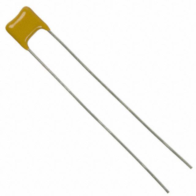
ICGOO电子元器件商城为您提供SR305C105KAATR1由AVX设计生产,在icgoo商城现货销售,并且可以通过原厂、代理商等渠道进行代购。 SR305C105KAATR1价格参考。AVXSR305C105KAATR1封装/规格:陶瓷电容器, 1µF ±10% 50V 陶瓷电容器 X7R 径向。您可以下载SR305C105KAATR1参考资料、Datasheet数据手册功能说明书,资料中有SR305C105KAATR1 详细功能的应用电路图电压和使用方法及教程。
AVX Corporation的陶瓷电容器型号SR305C105KAATR1是一种多层陶瓷电容器(MLCC),具有广泛的应用场景。以下是其主要应用场景和特点:

 1. 电源管理
该电容器常用于电源电路中的滤波和旁路应用,能够有效抑制电源噪声,确保电源电压的稳定性。在开关电源、线性稳压器等设备中,SR305C105KAATR1可以作为输出电容,帮助平滑输出电压,减少纹波。

 2. 信号调理
在模拟电路和数字电路中,该电容器可用于耦合和去耦,确保信号的完整性和稳定性。例如,在音频放大器、射频(RF)电路、传感器接口等应用中,它可以防止干扰信号进入敏感电路,保证信号传输的质量。

 3. 振荡电路
在时钟生成电路和振荡器中,SR305C105KAATR1可以用作定时元件,与电阻或其他元件配合,形成稳定的振荡频率。它适用于微控制器、通信模块等需要精确时钟源的设备。

 4. EMI/RFI抑制
该电容器具有良好的高频特性,能够在电磁兼容性(EMC)设计中发挥重要作用。它可以用来抑制电磁干扰(EMI)和射频干扰(RFI),尤其是在汽车电子、工业控制等领域,确保系统的抗干扰能力。

 5. 温度补偿
由于其具备较低的温度系数,SR305C105KAATR1适合用于对温度敏感的应用场景,如精密测量仪器、航空航天设备等。它能够在宽温度范围内保持稳定的电容值,减少因温度变化引起的性能波动。

 6. 消费电子
在智能手机、平板电脑、笔记本电脑等消费电子产品中,该电容器广泛应用于电源管理、信号处理和EMI抑制等环节,确保设备的可靠性和性能。

 总结
AVX Corporation的SR305C105KAATR1陶瓷电容器凭借其优异的电气性能和稳定性,广泛应用于电源管理、信号调理、振荡电路、EMI抑制、温度补偿以及消费电子等多个领域。它不仅能满足各种严苛的工作环境要求,还能为设计提供高可靠性保障。
| 参数 | 数值 |
| 产品目录 | |
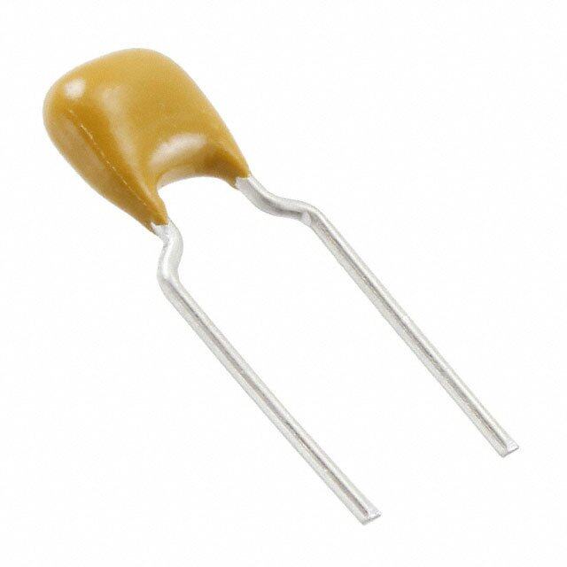
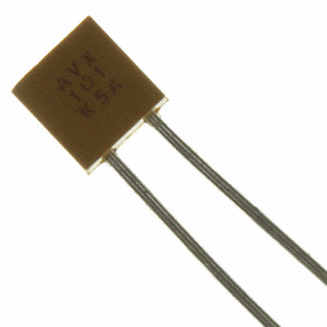
| 描述 | CAP CER 1UF 50V 10% RADIAL多层陶瓷电容器MLCC - 含引线 50volts 1uF 10% X7R |
| 产品分类 | |
| 品牌 | AVX |
| 产品手册 | |
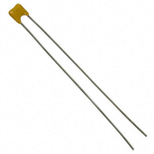
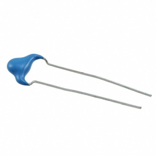
| 产品图片 |
|
| rohs | 符合RoHS无铅 / 符合限制有害物质指令(RoHS)规范要求 |
| 产品系列 | MLCC,多层陶瓷电容器MLCC - 含引线,AVX SR305C105KAATR1SkyCap® SR |
| 数据手册 | |
| 产品型号 | SR305C105KAATR1 |
| 产品 | General Type MLCCs |
| 产品种类 | 多层陶瓷电容器MLCC - 含引线 |
| 其它名称 | 478-7357-1 |
| 包装 | 剪切带 (CT) |
| 厚度(最大值) | - |
| 商标 | AVX |
| 商标名 | SkyCap |
| 外壳宽度 | 7.62 mm |
| 外壳高度 | 7.62 mm |
| 大小/尺寸 | 0.300" 长 x 0.150" 宽(7.62mm x 3.81mm) |
| 安装类型 | 通孔 |
| 容差 | 10 % |
| 封装 | Reel |
| 封装/外壳 | 径向 |
| 封装类型 | Conformally Coated |
| 工作温度 | -55°C ~ 125°C |
| 工作温度范围 | - 55 C to + 125 C |
| 工厂包装数量 | 2000 |
| 应用 | 通用 |
| 引线形式 | 直形 |
| 引线直径 | 0.508 mm |
| 引线间距 | 0.200"(5.08mm) |
| 引线间隔 | 5.08 mm |
| 最大工作温度 | + 125 C |
| 最小工作温度 | - 55 C |
| 标准包装 | 1 |
| 温度系数 | X7R |
| 温度系数/代码 | X7R |
| 特性 | - |
| 电压-额定 | 50V |
| 电压额定值 | 50 V |
| 电压额定值DC | 50 V |
| 电容 | 1 uF |
| 端接类型 | Radial |
| 等级 | - |
| 系列 | SR30 |
| 高度-安装(最大值) | 0.300"(7.62mm) |


- 商务部:美国ITC正式对集成电路等产品启动337调查
- 曝三星4nm工艺存在良率问题 高通将骁龙8 Gen1或转产台积电
- 太阳诱电将投资9.5亿元在常州建新厂生产MLCC 预计2023年完工
- 英特尔发布欧洲新工厂建设计划 深化IDM 2.0 战略
- 台积电先进制程称霸业界 有大客户加持明年业绩稳了
- 达到5530亿美元!SIA预计今年全球半导体销售额将创下新高
- 英特尔拟将自动驾驶子公司Mobileye上市 估值或超500亿美元
- 三星加码芯片和SET,合并消费电子和移动部门,撤换高东真等 CEO
- 三星电子宣布重大人事变动 还合并消费电子和移动部门
- 海关总署:前11个月进口集成电路产品价值2.52万亿元 增长14.8%


PDF Datasheet 数据手册内容提取
Radial Leads/SkyCap®/SR Series GENERAL INFORMATION Dimensions: Millimeters (Inches) W AVX SR Series Max. W Max. Conformally Coated Radial Leaded MLC H Max. H Max. Temperature Coefficients:C0G (NP0), X7R, Z5U T 1.0" Min. Max. 1.0" Min. LD T 200, 100, 50 Volts (300V, 400V & 500V also available) 1.52M (0a.x0.60) Nom. Max. LD Case Material:Epoxy Nom. See Note L.S. L.S. Lead Material:RoHS Compliant, 100% Tin Styles SR15, SR20, MWa x. SR30, SR40, SR50 H Max. Styles SR22, SR27 LD Nom. T Max. 1.0" Min. See Note Note: Coating clean .784 (0.031) min. above seating plane L.S. Style SR21 HOW TO ORDER Drawings are for illustrative purposes only. Actual lead form shape could vary within stated tolerances based on body size. SR21 5 E 104 M A R TR1 AVX Style Voltage Temperature Capacitance Capacitance Failure Rate Leads Packaging SR15 5 = 50V Coefficient First two digits are the Tolerance A = Not Applicable R = RoHS Blank = Bulk Packaging SR20 1 = 100V A = C0G (NP0) significant figures of C0G (NP0): X7R: Long Lead T = Trimmed Leads SR21 2 = 200V C = X7R capacitance. Third digit C = ±.25pF J = ±5% 1.0" minimum .230"± .030" SR22 9 = 300V E = Z5U indicates the additional D = ±.5pF K = ±10% Bulk packaging SR27 8 = 400V number of zeros. For F = ±1% M = ±20% TR1 = Tape and Reel SR30 7 = 500V example, order 100,000 (>50pF only) Packaging SR40 pF as 104. (For values G = ±2% Z5U: AP1 = Ammopack SR50 below 10pF use “R” in (>25pF only) M = ±20% Packaging place of decimal point, J = ±5% Z = +80% e.g., 1R4 = 1.4pF.) K = ±10% -20% See packaging specification page 33-34. MARKING PACKAGING REQUIREMENTS FRONT BACK Quantity per Bag XXX Capacitance Code XXX 3 Digit Date Code SR15, 20, 21, 22, 27, 30 1000 Pieces X X X Tolerance Code A XX Lot Code SR40, 50 500 Pieces Voltage Code Note: SR15, SR20, SR21, SR30, and SR40 available on tape and reel per EIA Temp. Char. Code AVX Logo specifications RS-468. See Pages 33 and 34. 14
Radial Leads/SkyCap®/SR Series C0G (NP0) Dielectric SIZE AND CAPACITANCE SPECIFICATIONS EIA Characteristic Dimensions: Millimeters (Inches) AVX Style SR15 SR20 SR21 SR22 SR27 SR30 SR40 SR50 AVX “Insertable” SR07 SR29 SR59 N/A N/A SR65 SR75 N/A Width 3.81 5.08 5.08 5.08 6.604 7.62 10.16 12.70 (W) (.150) (.200) (.200) (.200) (.260) (.300) (.400) (.500) Height 3.81 5.08 5.08 5.08 6.35 7.62 10.16 12.70 (H) (.150) (.200) (.200) (.200) (.250) (.300) (.400) (.500) Thickness 2.54 3.175 3.175 3.175 4.06 3.81 3.81 5.08 (T) (.100) (.125) (.125) (.125) (.160) (.150) (.150) (.200) Lead Spacing 2.54 2.54 5.08 6.35 7.62 5.08 5.08 10.16 (L.S.) (.100) (.100) (.200) (.250) (.300) (.200) (.200) (.400) Lead Diameter .508 .508 .508 .508 .508 .508 .508 .635 (L.D.) (.020) (.020) (.020) (.020) (.020) (.020) (.020) (.025) Cap. in.* Industry Preferred WVDC WVDC WVDC WVDC WVDC WVDC WVDC WVDC pF Values in Blue 200 100 50 200 100 50 200 100 50 200 100 50 200 100 50 100 50 100 50 100 50 1.0-9.9 SR151A1R0DAR 10 SR151A100KAR 15 SR-----A150KAR 22 SR-----A220KAR 33 SR-----A330KAR 39 SR-----A390KAR 47 SR-----A470KAR 68 SR-----A680KAR 100 SR151A101KAR 150 SR-----A151KAR 220 SR-----A221KAR 330 SR-----A331KAR 390 SR-----A391KAR 470 SR-----A471KAR 680 SR-----A681KAR 1000 SR211A102KAR 1500 SR-----A152KAR 2200 SR-----A222KAR 3900 SR-----A392KAR 4700 SR-----A472KAR 6800 SR-----A682KAR 8200 SR-----A822KAR 10,000 SR305A103KAR 15,000 SR-----A153KAR 22,000 SR-----A223KAR 33,000 SR-----A333KAR 39,000 SR-----A393KAR 47,000 SR-----A473KAR 68,000 SR-----A683KAR 100,000 SR-----A104KAR For other styles, voltages, tolerances and lead lengths see Part No. Codes or contact factory. *Other capacitance values available upon special request. = Industry preferred values = SR20 only Capacitance ranges available for SR12 and SR07 same as SR15 SR62 and SR59 same as SR21 SR64 and SR65 same as SR30 SR75 same as SR40 SR13 same as SR21 NOTE: For others voltages, tolerances, electrical specifications and NPO typical characteristics, see the AVX Multilayer Ceramic Leaded Capacitors Catalog. 15
Radial Leads/SkyCap®/SR Series X7R Dielectric SIZE AND CAPACITANCE SPECIFICATIONS EIA Characteristic Dimensions: Millimeters (Inches) AVX Style SR15 SR20 SR21 SR22 SR27 SR30 SR40 SR50 AVX “Insertable” SR07 SR29 SR59 N/A N/A SR65 SR75 N/A Width 3.81 5.08 5.08 5.08 6.604 7.62 10.16 12.70 (W) (.150) (.200) (.200) (.200) (.260) (.300) (.400) (.500) Height 3.81 5.08 5.08 5.08 6.35 7.62 10.16 12.70 (H) (.150) (.200) (.200) (.200) (.250) (.300) (.400) (.500) Thickness 2.54 3.175 3.175 3.175 4.06 3.81 3.81 5.08 (T) (.100) (.125) (.125) (.125) (.160) (.150) (.150) (.200) Lead Spacing 2.54 2.54 5.08 6.35 7.62 5.08 5.08 10.16 (L.S.) (.100) (.100) (.200) (.250) (.300) (.200) (.200) (.400) Lead Diameter .508 .508 .508 .508 .508 .508 .508 .635 (L.D.) (.020) (.020) (.020) (.020) (.020) (.020) (.020) (.025) Cap. in.* Industry Preferred WVDC WVDC WVDC WVDC WVDC WVDC WVDC WVDC pF Values in Blue 200 100 50 200 100 50 200 100 50 100 50 100 50 200 100 50 200 100 50 200 100 50 470 SR-----C471KAR 1000 SR155C102KAR 1500 SR-----C152KAR 2200 SR-----C222KAR 3300 SR-----C332KAR 4700 SR-----C472KAR 6800 SR-----C682KAR 10,000 SR215C103KAR 15,000 SR-----C153KAR 22,000 SR-----C223KAR 33,000 SR-----C333KAR 47,000 SR-----C473KAR 68,000 SR-----C683KAR 100,000 SR215C104KAR 150,000 SR-----C154KAR 220,000 SR215C224KAR 330,000 SR-----C334KAR 390,000 SR-----C394KAR 470,000 SR305C474KAR 1.0 uF SR305C105KAR 2.2 uF SR405C225KAR 2.7 uF SR505C275KAR 4.7 uF SR505C475KAR 10.0 uF SR655C106KAR For other styles, voltages, tolerances and lead lengths see Part No. Codes or contact factory. = Industry preferred values = Extended range = Extended range with 0.150" thickness maximum 16
Radial Leads/SkyCap®/SR Series Z5U Dielectric SIZE AND CAPACITANCE SPECIFICATIONS EIA Characteristic Dimensions: Millimeters (Inches) AVX Style SR15 SR20 SR21 SR22 SR27 SR30 SR40 SR50 AVX “Insertable” SR07 SR29 SR59 N/A N/A SR65 SR75 N/A Width 3.81 5.08 5.08 5.08 6.604 7.62 10.16 12.70 (W) (.150) (.200) (.200) (.200) (.260) (.300) (.400) (.500) Height 3.81 5.08 5.08 5.08 6.35 7.62 10.16 12.70 (H) (.150) (.200) (.200) (.200) (.250) (.300) (.400) (.500) Thickness 2.54 3.175 3.175 3.175 4.06 3.81 3.81 5.08 (T) (.100) (.125) (.125) (.125) (.160) (.150) (.150) (.200) Lead Spacing 2.54 2.54 5.08 6.35 7.62 5.08 5.08 10.16 (L.S.) (.100) (.100) (.200) (.250) (.300) (.200) (.200) (.400) Lead Diameter .508 .508 .508 .508 .508 .508 .508 .635 (L.D.) (.020) (.020) (.020) (.020) (.020) (.020) (.020) (.025) Cap. in.* Industry Preferred WVDC WVDC WVDC WVDC WVDC WVDC WVDC WVDC pF Values in Blue 100 50 100 50 100 50 100 50 100 50 100 50 100 50 100 50 10,000 SR155E103ZAR 47,000 SR-----E473ZAR 100,000 SR215E104ZAR 150,000 SR-----E154ZAR 220,000 SR215E224ZAR 330,000 SR215E334ZAR 470,000 SR215E474ZAR 680,000 SR-----E684ZAR 1.0 μF SR-----105ZAR 1.5 μF SR30E155ZAR 2.2 μF SR30E225ZAR 3.3 μF SR30E335ZAR 4.7 μF SR30E475ZAR For other styles, voltages, tolerances and lead lengths see Part No. Codes or contact factory. *Other capacitance values available upon special request. = Industry preferred values = SR20 only Capacitance ranges available for SR12 and SR07 same as SR15 SR62 and SR59 same as SR21 AVX 500 VOLT SKYCAPS** SR64 and SR65 same as SR30 SR75 same as SR40 MAXIMUM CAPACITANCE VALUE SR13 same as SR21 STYLE* C0G (NP0) X7R NOTE: For others voltages, tolerances, electrical specifications and NPO typical characteristics, see the AVX Multilayer Ceramic SR29 900 pF .015 μF Leaded Capacitors Catalog. SR20 1800 pF .033 μF SR28 900 pF .015 μF SR59 SR13 1800 pF .033 μF SR21 SR30 SR61 7200 pF .12 μF SR65 SR40 .015 μF .27 μF SR75 SR22 1800 pF .033 μF SR27 1800 pF .033 μF SR76 .015 μF .27 μF SR50 .036 μF .59 μF *Consult pages 27 and 28 for style sizes. **Voltage rating based on DWV of 150% of rated voltage. 17