ICGOO在线商城 > SQCFVA241JATME
- 型号: SQCFVA241JATME
- 制造商: AVX
- 库位|库存: xxxx|xxxx
- 要求:
| 数量阶梯 | 香港交货 | 国内含税 |
| +xxxx | $xxxx | ¥xxxx |
查看当月历史价格
查看今年历史价格
SQCFVA241JATME产品简介:
ICGOO电子元器件商城为您提供SQCFVA241JATME由AVX设计生产,在icgoo商城现货销售,并且可以通过原厂、代理商等渠道进行代购。 提供SQCFVA241JATME价格参考以及AVXSQCFVA241JATME封装/规格参数等产品信息。 你可以下载SQCFVA241JATME参考资料、Datasheet数据手册功能说明书, 资料中有SQCFVA241JATME详细功能的应用电路图电压和使用方法及教程。
| 参数 | 数值 |
| 产品目录 | |
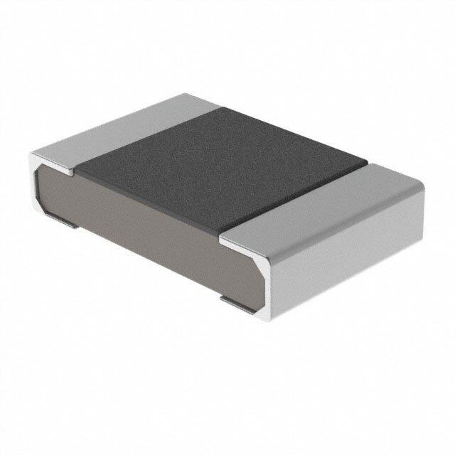
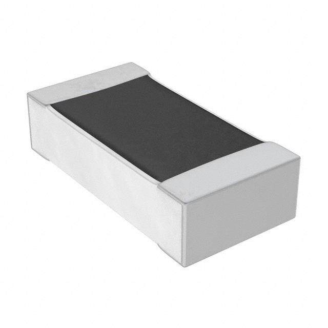
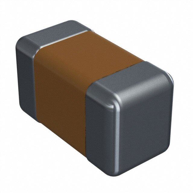
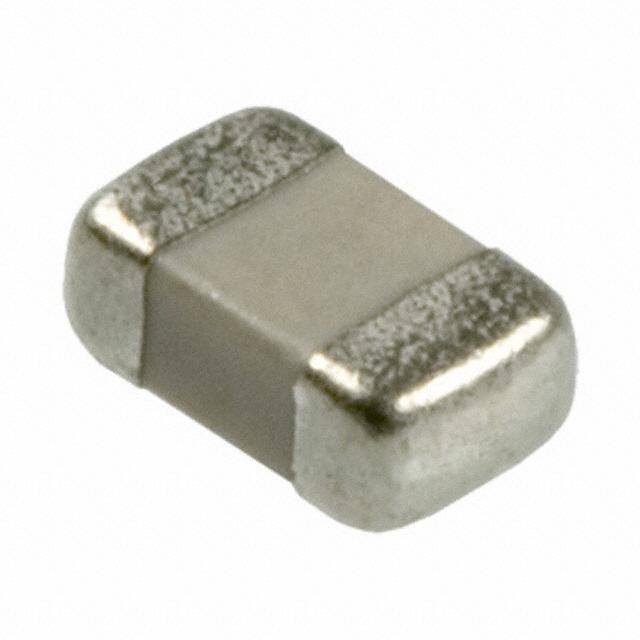
| 描述 | CAP CER 240PF 250V 5% 0805 |
| 产品分类 | |
| 品牌 | AVX Corporation |
| 数据手册 | |
| 产品图片 |
|
| 产品型号 | SQCFVA241JATME |
| rohs | 无铅 / 符合限制有害物质指令(RoHS)规范要求 |
| 产品系列 | SQ |
| 产品培训模块 | http://www.digikey.cn/PTM/IndividualPTM.page?site=cn&lang=zhs&ptm=21795 |
| 产品目录绘图 |
|
| 产品目录页面 | |
| 其它名称 | 478-4082-2 |
| 包装 | 带卷 (TR) |
| 厚度(最大值) | 0.045"(1.14mm) |
| 大小/尺寸 | 0.079" 长 x 0.049" 宽(2.01mm x 1.24mm) |
| 安装类型 | 表面贴装,MLCC |
| 容差 | ±5% |
| 封装/外壳 | 0805(2012 公制) |
| 工作温度 | -55°C ~ 125°C |
| 应用 | RF,微波,高频 |
| 引线形式 | - |
| 引线间距 | - |
| 标准包装 | 4,000 |
| 温度系数 | A |
| 特性 | 高 Q 值,低损耗 |
| 特色产品 | http://www.digikey.com/cn/zh/ph/avx/multilayercapacitors.html |
| 电压-额定 | 250V |
| 电容 | 240pF |
| 等级 | - |
| 高度-安装(最大值) | - |



- 商务部:美国ITC正式对集成电路等产品启动337调查
- 曝三星4nm工艺存在良率问题 高通将骁龙8 Gen1或转产台积电
- 太阳诱电将投资9.5亿元在常州建新厂生产MLCC 预计2023年完工
- 英特尔发布欧洲新工厂建设计划 深化IDM 2.0 战略
- 台积电先进制程称霸业界 有大客户加持明年业绩稳了
- 达到5530亿美元!SIA预计今年全球半导体销售额将创下新高
- 英特尔拟将自动驾驶子公司Mobileye上市 估值或超500亿美元
- 三星加码芯片和SET,合并消费电子和移动部门,撤换高东真等 CEO
- 三星电子宣布重大人事变动 还合并消费电子和移动部门
- 海关总署:前11个月进口集成电路产品价值2.52万亿元 增长14.8%


PDF Datasheet 数据手册内容提取
Microwave MLC’s SQCS (0603) SQCF (0805) Ultra Low ESR MLC FEATURES: (cid:129)Low ESR (cid:129)High Q (cid:129)High Self Resonance (cid:129)Capacitance Range 0.1 pF to 240 pF (cid:129)EIA Size APPLICATIONS: (cid:129)RF Power Amplifiers (cid:129)Low Noise Amplifiers (cid:129)Filter Networks (cid:129)Point to Point Radios HOW TO ORDER SQ CS V A 100 J A T 1A Case Size Capacitance Failure Rate Packaging Code CS = 0603 EIA Capacitance Code in pF. Code 1A = 7" Reel Unmarked CF = 0805 First two digits = significant A = Not ME = 7" Reel Marked AVX Style VColotadgee figures or “R” for decimal Applicable place. * Vertical T&R available V = 250V * 500 piece reels available Third digit = numberof zeros or after “R” significant figures. Capacitance Tolerance Code Temperature A = ±.05 pF Termination Coefficient Code Style Code B = ±.1 pF A = 0±30ppm/°C C = ±.25 pF **7 = Ag/Ni/Au J = Nickel Barrier D = ±.5 pF Sn/Pb (60/40) F = ±1% **T = 100% Tin G = ±2% (Standard) J = ±5% **RoHS compliant W L MECHANICAL DIMENSIONS: inches (millimeters) T A101J Case Length (L) Width (W) Thickness (T) Band Width (bw) SQCS .063±.006 .032±.006 .030 Max. .014±.006 (1.60±.152) (.813±.152) (.762) (.357±.152) bw SQCF .079±.008 .049±.008 .045 Max. .014±.006 (2.01±.200) (1.24±.200) (1.14) (.357±.152) TAPE & REEL: All tape and reel specifications are in compliance with EIA RS481 (equivalent to IEC 286 part 3). —8mm carrier —7" reel = 4000 pcs (500 piece options) Not RoHS Compliant LEAD-FREE COMPATIBLE COMPONENT For RoHS compliant products, 8 please select correct termination style. 199 12132017
Microwave MLC’s Low ESR MLC Capacitors ELECTRICAL SPECIFICATIONS Temperature Coefficient (TCC) (A) 0 ± 30 PPM/ºC Operating Temperature -55ºC to +125ºC Quality Factor (Q) Greater than 10,000 at 1 MHz Insulation Resistance (IR) 0.1 pF to 240 pF 105Megohms min. @ 25ºC at rated WVDC 104Megohms min. @ 125ºC at rated WVDC Working Voltage (WVDC) See Capacitance Values table Dielectric Withstanding Voltage (DWV) 250% of rated WVDC for 5 secs Aging Effects None Piezoelectric Effects None Capacitance Drift ± (0.02% or 0.02 pF), whichever is greater ENVIRONMENTAL CHARACTERISTICS AVX SQ will meet and exceed the requirements of EIA-198, MIL-PRF-55681 and MIL-PRF-123 Themal Shock Mil-STD-202, Method 107, Condition A Moisture Resistance Mil-STD-202, Method 106 Low Voltage Humidity Mil-STD-202, Method 103, condition A, with 1.5 VDC applied while subjected to an environment of 85ºC with 85% relative humidity for 240 hours Life Test Mil-STD-202, Method 108, for 2000 hours at 125ºC Shock Mil-STD-202, Method 213, Condition J Vibration Mil-STD-202, Method 204, Condition B Immersion Mil-STD-202, Method 104, Condition B Salt Spray Mil-STD-202, Method 101, Condition B Solderability Mil-STD-202, Method 208 Terminal Strength Mil-STD-202, Method 211 Temperature Cycling Mil-STD-202, Method 102, Condition C Barometric Pressure Mil-STD-202, Method 105, Condition B Resistance to Solder Heat Mil-STD-202, Method 210, Condition C 8 200
Microwave MLC’s SQ Series Available Capacitance/Size/WVDC/T.C. TABLE I: TC: A (0±30PPM/°C) CASE SIZE S Cap. pF Cap. Tol. WVDC Cap. pF Cap. Tol. WVDC Cap. pF Cap. Tol. WVDC 0.1 A, B 250 2.4 A, B, C 250 18 F, G, J 250 0.2 A, B 250 2.7 A, B, C 250 20 F, G, J 250 0.3 A, B 250 3.0 A, B, C 250 22 F, G, J 250 0.4 A, B 250 3.3 A, B, C 250 24 F, G, J 250 0.5 A, B, C 250 3.6 A, B, C 250 27 F, G, J 250 0.6 A, B, C 250 3.9 A, B, C 250 30 F, G, J 250 0.7 A, B, C 250 4.3 A, B, C 250 33 F, G, J 250 0.8 A, B, C 250 4.7 A, B, C 250 36 F, G, J 250 0.9 A, B, C 250 5.1 A, B, C 250 39 F, G, J 250 1.0 A, B, C 250 5.6 A, B, C 250 43 F, G, J 250 1.1 A, B, C 250 6.2 A, B, C 250 47 F, G, J 250 1.2 A, B, C 250 6.8 B, C, D 250 51 F, G, J 250 1.3 A, B, C 250 7.5 B, C, D 250 56 F, G, J 250 1.4 A, B, C 250 8.2 B, C, D 250 62 F, G, J 250 1.5 A, B, C 250 9.1 B, C, D 250 68 F, G, J 250 1.6 A, B, C 250 10 F, G, J 250 75 F, G, J 250 1.7 A, B, C 250 11 F, G, J 250 82 F, G, J 250 1.8 A, B, C 250 12 F, G, J 250 91 F, G, J 250 1.9 A, B, C 250 13 F, G, J 250 100 F, G, J 250 2.0 A, B, C 250 15 F, G, J 250 2.2 A, B, C 250 16 F, G, J 250 TABLE II: TC: A (0±30PPM/°C) CASE SIZE F Cap. pF Cap. Tol. WVDC Cap. pF Cap. Tol. WVDC Cap. pF Cap. Tol. WVDC Cap. pF Cap. Tol. WVDC 0.1 A, B 250 2.4 A, B, C 250 18 F, G, J 250 150 F, G, J 250 0.2 A, B 250 2.7 A, B, C 250 20 F, G, J 250 180 F, G, J 250 0.3 A, B 250 3.0 A, B, C 250 22 F, G, J 250 200 F, G, J 250 0.4 A, B 250 3.3 A, B, C 250 24 F, G, J 250 220 F, G, J 250 0.5 A, B, C 250 3.6 A, B, C 250 27 F, G, J 250 240 F, G, J 250 0.6 A, B, C 250 3.9 A, B, C 250 30 F, G, J 250 0.7 A, B, C 250 4.3 A, B, C 250 33 F, G, J 250 0.8 A, B, C 250 4.7 A, B, C 250 36 F, G, J 250 0.9 A, B, C 250 5.1 A, B, C 250 39 F, G, J 250 1.0 A, B, C 250 5.6 A, B, C 250 43 F, G, J 250 1.1 A, B, C 250 6.2 A, B, C 250 47 F, G, J 250 1.2 A, B, C 250 6.8 B, C, D 250 51 F, G, J 250 1.3 A, B, C 250 7.5 B, C, D 250 56 F, G, J 250 1.4 A, B, C 250 8.2 B, C, D 250 62 F, G, J 250 1.5 A, B, C 250 9.1 B, C, D 250 68 F, G, J 250 1.6 A, B, C 250 10 F, G, J 250 75 F, G, J 250 1.7 A, B, C 250 11 F, G, J 250 82 F, G, J 250 1.8 A, B, C 250 12 F, G, J 250 91 F, G, J 250 1.9 A, B, C 250 13 F, G, J 250 100 F, G, J 250 2.0 A, B, C 250 15 F, G, J 250 110 F, G, J 250 2.2 A, B, C 250 16 F, G, J 250 120 F, G, J 250 8 201
Microwave MLC’s SQCS (0603) SQCF (0805) Ultra Low ESR MLC Typical ESR SQCS 1 1pF s) m 4.7pF h o 0.1 10pF ( R S 22pF E 100pF 0.01 10 100 1000 Frequency (Mhz) Typical ESR SQCF 1 1pF s) 0.1 m 4.7pF h o 10pF ( R S 0.01 100pF E 240pF 0.001 10 100 1000 Frequency (Mhz) 8 202
Microwave MLC’s SQCS (0603) SQCF (0805) Ultra Low ESR MLC Max Current SQCS 100 ) s p m 1pF a 10 ( 4.7pF t n e 10pF r r u C 22pF 1 x a 100pF M 0.1 10 100 1000 10000 Frequency (Mhz) Max Current SQCF 100 ) s p 1pF m 10 a 4.7pF ( t n 10pF e r ur 100pF C 1 x 240pF a M 0.1 10 100 1000 10000 Frequency (Mhz) 8 203
Microwave MLC’s SQCS (0603) SQCF (0805) Ultra Low ESR MLC Series Resonant Frequency 100000 10000 ) z h M SQCS ( F R SQCF S 1000 100 1 10 100 1000 Capacitance(pF) B MOUNTING PAD DIMENSIONS: inches (millimeters) A C Case A min B min C min D min SQCA 0.082(2.083) 0.051(1.295) 0.032(0.813) 0.130(3.302) SQCB 0.131(3.327) 0.051(1.295) 0.074(1.880) 0.177(4.496) D SQCS 0.038(0.965) 0.043(1.092) 0.025(0.635) 0.112(2.845) SQCF 0.059(1.499) 0.051(1.295) 0.024(0.610) 0.125(3.175) SQCS & SQCF ENGINEERING KITS PN Series Diel Term Range KitSQ1800LF 100%Tin .1 to10pF SQCF C0G KitSQ1900LF RoHS 10 to240pF KitSQ1500LF 100%Tin .1 to10pF SQCS C0G KitSQ1600LF RoHS 10 to100pF Tolerance perPF: B from .1 to3.3 J from 10 to240 C from 3.9 to8.2 8 204
 Datasheet下载


