- 型号: SN74LVC1G74RSE2
- 制造商: Texas Instruments
- 库位|库存: xxxx|xxxx
- 要求:
| 数量阶梯 | 香港交货 | 国内含税 |
| +xxxx | $xxxx | ¥xxxx |
查看当月历史价格
查看今年历史价格
SN74LVC1G74RSE2产品简介:
ICGOO电子元器件商城为您提供SN74LVC1G74RSE2由Texas Instruments设计生产,在icgoo商城现货销售,并且可以通过原厂、代理商等渠道进行代购。 SN74LVC1G74RSE2价格参考¥1.90-¥5.45。Texas InstrumentsSN74LVC1G74RSE2封装/规格:逻辑 - 触发器, 。您可以下载SN74LVC1G74RSE2参考资料、Datasheet数据手册功能说明书,资料中有SN74LVC1G74RSE2 详细功能的应用电路图电压和使用方法及教程。
| 参数 | 数值 |
| 产品目录 | 集成电路 (IC)半导体 |
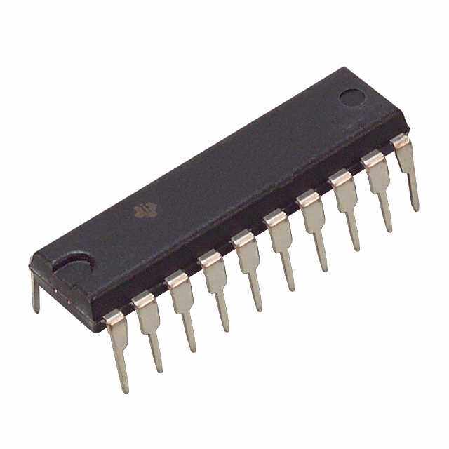
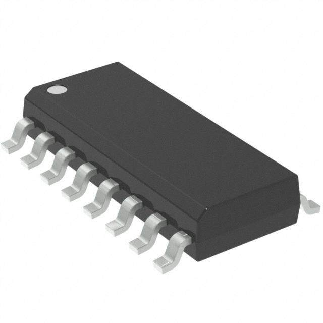
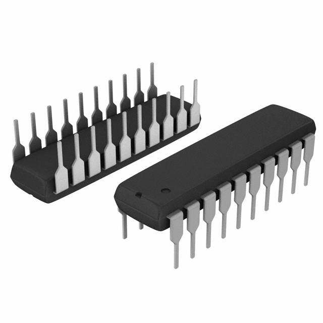
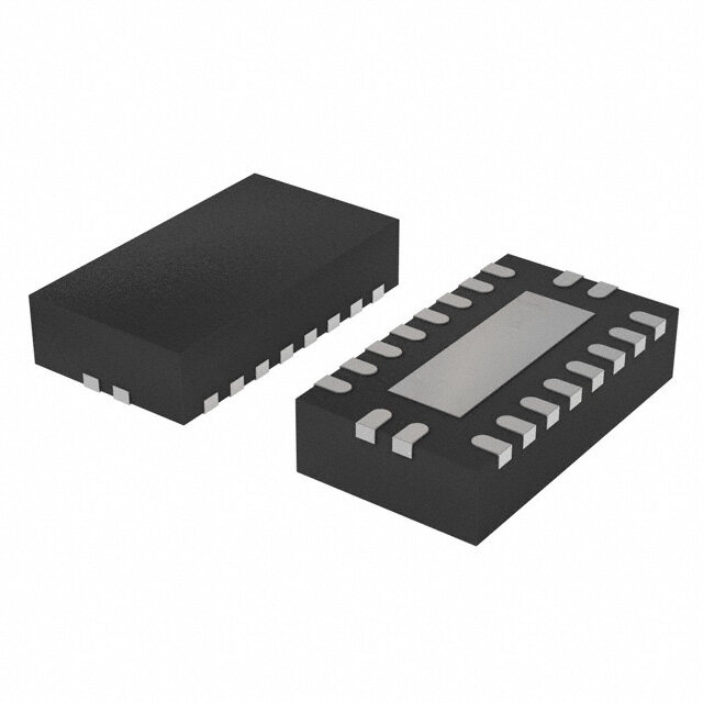
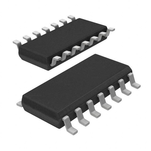
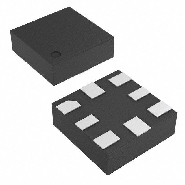
| 描述 | IC D-TYPE POS TRG SNGL 8UQFN触发器 Sgl Positive-Edge Triggered Flip-Flop |
| 产品分类 | |
| 品牌 | Texas Instruments |
| 产品手册 | |
| 产品图片 |
|
| rohs | 符合RoHS无铅 / 符合限制有害物质指令(RoHS)规范要求 |
| 产品系列 | 逻辑集成电路,触发器,Texas Instruments SN74LVC1G74RSE274LVC |
| 数据手册 | |
| 产品型号 | SN74LVC1G74RSE2 |
| 不同V、最大CL时的最大传播延迟 | 4.4ns @ 5V,50pF |
| 产品种类 | 触发器 |
| 传播延迟时间 | 4.4 ns |
| 低电平输出电流 | 16 mA |
| 元件数 | 1 |
| 其它名称 | 296-35530-1 |
| 功能 | 设置(预设)和复位 |
| 包装 | 剪切带 (CT) |
| 商标 | Texas Instruments |
| 安装类型 | 表面贴装 |
| 安装风格 | SMD/SMT |
| 封装 | Reel |
| 封装/外壳 | 8-UFQFN |
| 封装/箱体 | UQFN-8 |
| 工作温度 | -40°C ~ 85°C (TA) |
| 工厂包装数量 | 5000 |
| 最大工作温度 | + 85 C |
| 最小工作温度 | - 40 C |
| 极性 | Inverting, Non-Inverting |
| 标准包装 | 1 |
| 每元件位数 | 1 |
| 电压-电源 | 1.65 V ~ 5.5 V |
| 电流-输出高,低 | 32mA,32mA |
| 电流-静态 | 10µA |
| 电源电压-最大 | 5.5 V |
| 电源电压-最小 | 1.65 V |
| 电路数量 | 1 |
| 类型 | D 型 |
| 系列 | SN74LVC1G74 |
| 触发器类型 | 正边沿 |
| 输入电容 | 5pF |
| 输入类型 | CMOS |
| 输入线路数量 | 1 |
| 输出类型 | 差分 |
| 输出线路数量 | 1 |
| 逻辑类型 | Positive Edge Triggered D Flip-Flop |
| 逻辑系列 | SN74 |
| 频率-时钟 | 200MHz |
| 高电平输出电流 | - 16 mA |





- 商务部:美国ITC正式对集成电路等产品启动337调查
- 曝三星4nm工艺存在良率问题 高通将骁龙8 Gen1或转产台积电
- 太阳诱电将投资9.5亿元在常州建新厂生产MLCC 预计2023年完工
- 英特尔发布欧洲新工厂建设计划 深化IDM 2.0 战略
- 台积电先进制程称霸业界 有大客户加持明年业绩稳了
- 达到5530亿美元!SIA预计今年全球半导体销售额将创下新高
- 英特尔拟将自动驾驶子公司Mobileye上市 估值或超500亿美元
- 三星加码芯片和SET,合并消费电子和移动部门,撤换高东真等 CEO
- 三星电子宣布重大人事变动 还合并消费电子和移动部门
- 海关总署:前11个月进口集成电路产品价值2.52万亿元 增长14.8%





PDF Datasheet 数据手册内容提取
Product Sample & Technical Tools & Support & Folder Buy Documents Software Community SN74LVC1G74 SCES794E–OCTOBER2009–REVISEDJANUARY2015 SN74LVC1G74 Single Positive-Edge-Triggered D-Type Flip-Flop with Clear and Preset 1 Features 3 Description • AvailableintheTexasInstruments This single positive-edge-triggered D-type flip-flop is 1 designedfor1.65-Vto5.5-VV operation. NanoFree™Package CC • Supports5-VV Operation NanoFree™ package technology is a major CC breakthrough in IC packaging concepts, using the die • InputsAcceptVoltagesto5.5V asthepackage. • SupportsDownTranslationtoV CC A low level at the preset (PRE) or clear (CLR) input • Maxt of5.9nsat3.3V pd sets or resets the outputs, regardless of the levels of • LowPowerConsumption,10-µAMaxICC the other inputs. When PRE and CLR are inactive • ±24-mAOutputDriveat3.3V (high), data at the data (D) input meeting the setup time requirements is transferred to the outputs on the • TypicalV (OutputGroundBounce) OLP positive-going edge of the clock pulse. Clock <0.8VatV =3.3V,T =25°C CC A triggering occurs at a voltage level and is not related • TypicalV (OutputV Undershoot) OHV OH directly to the rise time of the clock pulse. Following >2VatVCC=3.3V,TA=25°C the hold-time interval, data at the D input can be • I SupportsLiveInsertion,Partial-Power-Down changedwithoutaffectingthelevelsattheoutputs. off Mode,andBack-DriveProtection This device is fully specified for partial-power-down • Latch-UpPerformanceExceeds100mAPer applications using I . The I circuitry disables the off off JESD78,ClassII outputs, preventing damaging current backflow throughthedevicewhenitispowereddown. • ESDProtectionExceedsJESD22 – 2000-VHuman-BodyModel DeviceInformation(1) – 200-VMachineModel PARTNUMBER PACKAGE BODYSIZE – 1000-VCharged-DeviceModel SM8(8) 2.95mm×2.80mm US8(8) 2.30mm×2.00mm 2 Applications SN74LVC1G74 X2SON(8) 1.40mm×1.00mm • Servers UQFN(8) 1.50mm×1.50mm • LEDDisplays (1) For all available packages, see the orderable addendum at • Networkswitch theendofthedatasheet. • TelecomInfrastructure • MotorDrivers • I/OExpanders 4 Simplified Schematic PRE D Q CLK Q CLR 1 An IMPORTANT NOTICE at the end of this data sheet addresses availability, warranty, changes, use in safety-critical applications, intellectualpropertymattersandotherimportantdisclaimers.PRODUCTIONDATA.
SN74LVC1G74 SCES794E–OCTOBER2009–REVISEDJANUARY2015 www.ti.com Table of Contents 1 Features.................................................................. 1 9 DetailedDescription.............................................. 9 2 Applications........................................................... 1 9.1 Overview...................................................................9 3 Description............................................................. 1 9.2 FunctionalBlockDiagram.........................................9 4 SimplifiedSchematic............................................. 1 9.3 FeatureDescription...................................................9 9.4 DeviceFunctionalModes..........................................9 5 RevisionHistory..................................................... 2 10 ApplicationandImplementation........................ 10 6 PinConfigurationandFunctions......................... 3 10.1 ApplicationInformation ........................................10 7 Specifications......................................................... 4 10.2 TypicalPowerButtonCircuit................................10 7.1 AbsoluteMaximumRatings .....................................4 11 PowerSupplyRecommendations..................... 11 7.2 ESDRatings..............................................................4 12 Layout................................................................... 12 7.3 RecommendedOperatingConditions......................5 7.4 ThermalInformation..................................................5 12.1 LayoutGuidelines.................................................12 7.5 ElectricalCharacteristics...........................................6 12.2 LayoutExample....................................................12 7.6 TimingRequirements................................................6 13 DeviceandDocumentationSupport................. 12 7.7 SwitchingCharacteristics..........................................6 13.1 Trademarks...........................................................12 7.8 OperatingCharacteristics..........................................7 13.2 ElectrostaticDischargeCaution............................12 7.9 TypicalCharacteristics..............................................7 13.3 Glossary................................................................12 8 ParameterMeasurementInformation..................8 14 Mechanical,Packaging,andOrderable Information........................................................... 12 5 Revision History ChangesfromRevisionD(January2013)toRevisionE Page • AddedApplications,DeviceInformationtable,PinFunctionstable,ESDRatingstable,ThermalInformationtable, TypicalCharacteristics,FeatureDescriptionsection,DeviceFunctionalModes,ApplicationandImplementation section,PowerSupplyRecommendationssection,Layoutsection,DeviceandDocumentationSupportsection,and Mechanical,Packaging,andOrderableInformationsection.................................................................................................. 1 • DeletedOrderingInformationtable........................................................................................................................................ 1 • UpdatedFeatures................................................................................................................................................................... 1 ChangesfromOriginal(October2009)toRevisionA Page • ChangedI descriptioninFeatures....................................................................................................................................... 1 off • ChangedTimingRequirementstable..................................................................................................................................... 6 • ChangedSwitchingRequirementstable................................................................................................................................ 6 2 SubmitDocumentationFeedback Copyright©2009–2015,TexasInstrumentsIncorporated ProductFolderLinks:SN74LVC1G74
SN74LVC1G74 www.ti.com SCES794E–OCTOBER2009–REVISEDJANUARY2015 6 Pin Configuration and Functions DCTPACKAGE DCUPACKAGE (TOPVIEW) (TOPVIEW) CLK 1 8 V CLK 1 8 VCC CC D 2 7 PRE D 2 7 PRE Q 3 6 CLR GND 4 5 Q Q 3 6 CLR GND 4 5 Q See mechanical drawingsfor dimensions. DQEPACKAGE RSEPACKAGE (TOPVIEW) (TOPVIEW) V CLK 18 VCC C8C D 2 7 PRE PRE 1 7 CLK Q 3 6 CLR CLR 2 6 D GND 4 5 Q Q 3 4 5 Q GND See mechanical drawingsfor dimensions PinFunctions PIN TYPE DESCRIPTION NAME NO. CLK 1 I Clockinput CLR 6 I Clearinput-PulllowtosetQoutputlow D 2 I Input GND 4 — Ground Q 5 O Output Q 3 O Invertedoutput PRE 7 I Presetinput-PulllowtosetQoutputhigh V 8 — Supply CC Copyright©2009–2015,TexasInstrumentsIncorporated SubmitDocumentationFeedback 3 ProductFolderLinks:SN74LVC1G74
SN74LVC1G74 SCES794E–OCTOBER2009–REVISEDJANUARY2015 www.ti.com 7 Specifications 7.1 Absolute Maximum Ratings overoperatingfree-airtemperaturerange(unlessotherwisenoted)(1) MIN MAX UNIT V Supplyvoltagerange –0.5 6.5 V CC V Inputvoltagerange(2) –0.5 6.5 V I V Voltagerangeappliedtoanyoutputinthehigh-impedanceorpower-offstate(2) –0.5 6.5 V O V Voltagerangeappliedtoanyoutputinthehighorlowstate(2)(3) –0.5 V +0.5 V O CC I Inputclampcurrent V <0 –50 mA IK I I Outputclampcurrent V <0 –50 mA OK O I Continuousoutputcurrent ±50 mA O ContinuouscurrentthroughV orGND ±100 mA CC T Storagetemperaturerange –65 150 °C stg (1) StressesbeyondthoselistedunderAbsoluteMaximumRatingsmaycausepermanentdamagetothedevice.Thesearestressratings only,andfunctionaloperationofthedeviceattheseoranyotherconditionsbeyondthoseindicatedunderRecommendedOperating Conditionsisnotimplied.Exposuretoabsolute-maximum-ratedconditionsforextendedperiodsmayaffectdevicereliability. (2) Theinputnegative-voltageandoutputvoltageratingsmaybeexceedediftheinputandoutputclamp-currentratingsareobserved. (3) ThevalueofV isprovidedintheRecommendedOperatingConditionstable. CC 7.2 ESD Ratings PARAMETER DEFINITION VALUE UNIT Humanbodymodel(HBM),perANSI/ESDA/JEDECJS-001,allpins(1) 2000 V(ESD) Electrostaticdischarge Chargeddevicemodel(CDM),perJEDECspecificationJESD22-C101,all V pins(2) 1000 (1) JEDECdocumentJEP155statesthat500-VHBMallowssafemanufacturingwithastandardESDcontrolprocess. (2) JEDECdocumentJEP157statesthat250-VCDMallowssafemanufacturingwithastandardESDcontrolprocess. 4 SubmitDocumentationFeedback Copyright©2009–2015,TexasInstrumentsIncorporated ProductFolderLinks:SN74LVC1G74
SN74LVC1G74 www.ti.com SCES794E–OCTOBER2009–REVISEDJANUARY2015 7.3 Recommended Operating Conditions overoperatingfree-airtemperaturerange(unlessotherwisenoted)(1) MIN MAX UNIT Operating 1.65 5.5 V Supplyvoltage V CC Dataretentiononly 1.5 V =1.65Vto1.95V 0.65×V CC CC V =2.3Vto2.7V 1.7 CC V High-levelinputvoltage V IH V =3Vto3.6V 2 CC V =4.5Vto5.5V 0.7×V CC CC V =1.65Vto1.95V 0.35×V CC CC V =2.3Vto2.7V 0.7 CC V Low-levelinputvoltage V IL V =3Vto3.6V 0.8 CC V =4.5Vto5.5V 0.3×V CC CC V Inputvoltage 0 5.5 V I V Outputvoltage 0 V V O CC V =1.65V –4 CC V =2.3V –8 CC I High-leveloutputcurrent –16 mA OH V =3V CC –24 V =4.5V –32 CC V =1.65V 4 CC V =2.3V 8 CC I Low-leveloutputcurrent 16 mA OL V =3V CC 24 V =4.5V 32 CC V =1.8V±0.15V,2.5V±0.2V 20 CC Δt/Δv Inputtransitionriseorfallrate V =3.3V±0.3V 10 ns/V CC V =5V±0.5V 5 CC RSEPackage –40 85 DQEPackage T Operatingfree-airtemperature °C A DCTPackage –40 125 DCUPackage (1) AllunusedinputsofthedevicemustbeheldatV orGNDtoensureproperdeviceoperation.RefertotheTIapplicationreport, CC ImplicationsofSloworFloatingCMOSInputs,literaturenumberSCBA004. 7.4 Thermal Information SN74LVC1G74 THERMALMETRIC(1) DCT DCU RSE DQE UNIT 8PINS 8PINS 8PINS 8PINS R Junction-to-ambientthermalresistance 220 227 243 261 °C/W θJA (1) Formoreinformationabouttraditionalandnewthermalmetrics,seetheICPackageThermalMetricsapplicationreport,SPRA953. Copyright©2009–2015,TexasInstrumentsIncorporated SubmitDocumentationFeedback 5 ProductFolderLinks:SN74LVC1G74
SN74LVC1G74 SCES794E–OCTOBER2009–REVISEDJANUARY2015 www.ti.com 7.5 Electrical Characteristics overrecommendedoperatingfree-airtemperaturerange(unlessotherwisenoted) PARAMETER TESTCONDITIONS V MIN TYP(1) MAX UNIT CC I =–100µA 1.65Vto5.5V V –0.1 OH CC I =–4mA 1.65V 1.2 OH I =–8mA 2.3V 1.9 OH V V OH I =–16mA 2.4 OH 3V I =–24mA 2.3 OH I =–32mA 4.5V 3.8 OH I =100µA 1.65Vto5.5V 0.1 OL I =4mA 1.65V 0.45 OL I =8mA 2.3V 0.3 OL V V OL I =16mA 0.4 OL 3V I =24mA 0.55 OL I =32mA 4.5V 0.55 OL Dataor I V =5.5VorGND 0to5.5V ±5 µA I controlinputs I I V orV =5.5V 0 ±10 µA off I O I V =5.5VorGND, I =0 1.65Vto5.5V 10 µA CC I O ΔI OneinputatV –0.6V, OtherinputsatV orGND 3Vto5.5V 500 µA CC CC CC C V =V orGND 3.3V 5 pF i I CC (1) AlltypicalvaluesareatV =3.3V,T =25°C. CC A 7.6 Timing Requirements overrecommendedoperatingfree-airtemperaturerange(unlessotherwisenoted)(seeFigure3) –40°Cto85°C –40°Cto125°C FROM TO PARAMETER V =1.8V V =2.5V V =3.3V V =5V V =3.3V V =5V UNIT (INPUT) (OUTPUT) CC CC CC CC CC CC MIN MAX MIN MAX MIN MAX MIN MAX MIN MAX MIN MAX f 80 175 175 200 175 200 MHz clock CLK 6.2 2.7 2.7 2 2.7 2 t ns w PREorCLRlow 6.2 2.7 2.7 2 2.7 2 Data 2.9 1.7 1.3 1.1 1.3 1.1 t ns su PREorCLRinactive 1.9 1.4 1.2 1 1.2 1.2 t 0 0.3 1.2 0.5 1.2 0.5 ns h 7.7 Switching Characteristics overrecommendedoperatingfree-airtemperaturerange(unlessotherwisenoted)(seeFigure3) –40°Cto85°C –40°Cto125°C FROM TO PARAMETER V =1.8V V =2.5V V =3.3V V =5V V =3.3V V =5V UNIT (INPUT) (OUTPUT) CC CC CC CC CC CC MIN MAX MIN MAX MIN MAX MIN MAX MIN MAX MIN MAX f 80 175 175 200 175 200 MHz max Q 4.8 13.4 2.2 7.1 2.2 5.9 1.4 4.1 2.2 7.9 1.4 6.1 CLK Q 6 14.4 3 7.7 2.6 6.2 1.6 4.4 2.6 8.2 1.6 6.4 t ns pd PREorCLR QorQ 4.4 12.9 2.3 7 1.7 5.9 1.6 4.1 1.7 7.9 1.6 6.1 low 6 SubmitDocumentationFeedback Copyright©2009–2015,TexasInstrumentsIncorporated ProductFolderLinks:SN74LVC1G74
SN74LVC1G74 www.ti.com SCES794E–OCTOBER2009–REVISEDJANUARY2015 7.8 Operating Characteristics T =25°C A V =1.8V V =2.5V V =3.3V V =5V CC CC CC CC PARAMETER TESTCONDITIONS UNIT TYP TYP TYP TYP C Powerdissipationcapacitance f=10MHz 35 35 37 40 pF pd 7.9 Typical Characteristics 14 10 VCC=3V, VCC=3V, TA=25°C TA=25°C 12 s –ns OneOutputSwitching e–n 8 OneOutputSwitching e m Tim 10 yTi y a ela Del D 8 n 6 n o atio gati g a a 6 p p o o r Pr –P 4 – d d 4 p p t t 2 2 0 50 100 150 200 250 300 0 50 100 150 200 250 300 CL–LoadCapacitance–pF CL–LoadCapacitance–pF Figure1.PropagationDelay(LowtoHighTransition) Figure2.PropagationDelay(HightoLowTransition) vsLoadCapacitance vsLoadCapacitance Copyright©2009–2015,TexasInstrumentsIncorporated SubmitDocumentationFeedback 7 ProductFolderLinks:SN74LVC1G74
SN74LVC1G74 SCES794E–OCTOBER2009–REVISEDJANUARY2015 www.ti.com 8 Parameter Measurement Information V LOAD R S1 Open From Output L TEST S1 Under Test GND t /t Open C PLH PHL (see NoteA)L RL tPLZ/tPZL VLOAD t /t GND PHZ PZH LOAD CIRCUIT INPUTS V V V C R V CC V t/t M LOAD L L D I r f 1.8 V±0.15 V V £2 ns V /2 2 ×V 30 pF 1 kW 0.15 V CC CC CC 2.5 V±0.2 V V £2 ns V /2 2 ×V 30 pF 500W 0.15 V CC CC CC 3.3 V±0.3 V 3 V £2.5 ns 1.5 V 6 V 50 pF 500W 0.3 V 5 V±0.5 V V £2.5 ns V /2 2 ×V 50 pF 500W 0.3 V CC CC CC V I Timing Input V M 0 V t W VI tsu th V Input V V I M M Data Input V V M M 0 V 0 V VOLTAGE WAVEFORMS VOLTAGE WAVEFORMS PULSE DURATION SETUPAND HOLD TIMES Input VM VM VI COounttpruotl VM VM VI 0 V 0 V t t t t PLH PHL PZL PLZ V Output V /2 Output VM VM OH WSav1e afot rVm 1 VM V + V LOAD VOL (see NoteL OBAD) OL D VOL t t PHL PLH t t PZH PHZ Output VM VM VOH WSa1v eaOfto uGrtmpNu D2t VM VOH–VD VOH VOL (see Note B) »0 V VOLTAGE WAVEFORMS VOLTAGE WAVEFORMS PROPAGATION DELAYTIMES ENABLEAND DISABLE TIMES INVERTINGAND NONINVERTING OUTPUTS LOW-AND HIGH-LEVELENABLING NOTES: A. C includes probe and jig capacitance. L B. Waveform 1 is for an output with internal conditions such that the output is low, except when disabled by the output control. Waveform 2 is for an output with internal conditions such that the output is high, except when disabled by the output control. C. All input pulses are supplied by generators having the following characteristics: PRR£10 MHz, Z = 50W. O D. The outputs are measured one at a time, with one transition per measurement. E. t and t are the same as t . PLZ PHZ dis F. t and t are the same as t . PZL PZH en G.t and t are the same as t . PLH PHL pd H. All parameters and waveforms are not applicable to all devices. Figure3. LoadCircuitandVoltageWaveforms 8 SubmitDocumentationFeedback Copyright©2009–2015,TexasInstrumentsIncorporated ProductFolderLinks:SN74LVC1G74
SN74LVC1G74 www.ti.com SCES794E–OCTOBER2009–REVISEDJANUARY2015 9 Detailed Description 9.1 Overview This device is fully specified for partial-power-down applications using I . The I circuitry disables the outputs, off off preventingdamagingcurrentbackflowthroughthedevicewhenitispowereddown. 9.2 Functional Block Diagram 7 PRE CLK 1 C C C 5 Q TG C C C C 2 D TG TG TG 3 Q C C C 6 CLR 9.3 Feature Description • Allowdownvoltagetranslation – 5Vto3.3V – 5.0Vto1.8V – 3.3Vto1.8V • Inputsacceptvoltagelevelsupto5.5V • I Feature off – Canpreventbackflowcurrentthatcandamagedevicewhenpowereddown 9.4 Device Functional Modes Table1.FunctionTable INPUTS OUTPUTS PRE CLR CLK D Q Q L H X X H L H L X X L H L L X X H(1) H(1) H H ↑ H H L H H ↑ L L H H H L X Q Q 0 0 (1) Thisconfigurationisnonstable;thatis,itdoesnotpersistwhenPREorCLRreturnstoitsinactive(high)level. Copyright©2009–2015,TexasInstrumentsIncorporated SubmitDocumentationFeedback 9 ProductFolderLinks:SN74LVC1G74
SN74LVC1G74 SCES794E–OCTOBER2009–REVISEDJANUARY2015 www.ti.com 10 Application and Implementation NOTE Information in the following applications sections is not part of the TI component specification, and TI does not warrant its accuracy or completeness. TI’s customers are responsible for determining suitability of components for their purposes. Customers should validateandtesttheirdesignimplementationtoconfirmsystemfunctionality. 10.1 Application Information A low level at the preset (PRE) or clear (CLR) input sets or resets the outputs, regardless of the levels of the other inputs. When PRE and CLR are inactive (high), data at the data (D) input meeting the setup time requirements is transferred to the outputs on the positive-going edge of the clock pulse. Clock triggering occurs at a voltage level and is not related directly to the rise time of the clock pulse. Following the hold-time interval, dataattheDinputcanbechangedwithoutaffectingthelevelsattheoutputs. The resistor and capacitor at the CLR pin are optional. If they are not used, the CLR pin should be connected directlytoV tobeinactive. CC 10.2 Typical Power Button Circuit 3 V 3 V 3 V NC VCC A GND Y CLK VCC SN74LVC1G17 D PRE Q CLR MCU GND Q SN74LVC1G74 Figure4. DevicePowerButtonCircuit 10.2.1 DesignRequirements This device uses CMOS technology and has balanced output drive. Care should be taken to avoid bus contention because it can drive currents that would exceed maximum limits. Outputs can be combined to producehigherdrivebutthehighdrivewillalsocreatefasteredgesintolightloadssoroutingandloadconditions shouldbeconsideredtopreventringing. 10.2.2 DetailedDesignProcedure 1. RecommendedInputConditions: – Forrisetimeandfalltimespecifications,see(Δt/ΔV)inRecommendedOperatingConditions table. – Forspecifiedhighandlowlevels,see(V andV )inRecommendedOperatingConditions table. IH IL – Inputsareovervoltagetolerantallowingthemtogoashighas5.5VatanyvalidV . CC 2. RecommendOutputConditions: – Loadcurrentsshouldnotexceed50mAperoutputand100mAtotalforthepart. – Series resistors on the output may be used if the user desires to slow the output edge signal or limit the 10 SubmitDocumentationFeedback Copyright©2009–2015,TexasInstrumentsIncorporated ProductFolderLinks:SN74LVC1G74
SN74LVC1G74 www.ti.com SCES794E–OCTOBER2009–REVISEDJANUARY2015 Typical Power Button Circuit (continued) outputcurrent. 10.2.3 ApplicationCurves 60 100 TA=25°C,VCC=3V, TA=25°C,VCC=3V, 40 VIH=3V,VIL=0V, VIH=3V,VIL=0V, AllOutputsSwitching 80 AllOutputsSwitching 20 60 0 A A m m – –20 – 40 OH OL I I –40 20 –60 0 –80 –100 –20 –1 –0.5 0.0 0.5 1.0 1.5 2.0 2.5 3.0 3.5 4.0 –0.2 0.0 0.2 0.4 0.6 0.8 1.0 1.2 1.4 1.6 VOH–V VOL–V Figure5.OutputCurrentDrive Figure6.OutputCurrentDrive vsHIGH-levelOutputVoltage vsLOW-levelOutputVoltage 11 Power Supply Recommendations The power supply can be any voltage between the minimum and maximum supply voltage rating located in the Recommended Operating Conditions table. Each V terminal should have a good bypass capacitor to prevent CC powerdisturbance.Fordeviceswithasinglesupply,a0.1-μFcapacitorisrecommendedandiftherearemultiple V terminals then .01-μF or .022-μF capacitors are recommended for each power terminal. It is acceptable to CC parallel multiple bypass caps to reject different frequencies of noise. The 0.1-μF and 1-μF capacitors are commonly used in parallel. The bypass capacitor should be installed as close to the power terminal as possible forbestresults. Copyright©2009–2015,TexasInstrumentsIncorporated SubmitDocumentationFeedback 11 ProductFolderLinks:SN74LVC1G74
SN74LVC1G74 SCES794E–OCTOBER2009–REVISEDJANUARY2015 www.ti.com 12 Layout 12.1 Layout Guidelines When using multiple bit logic devices, inputs should not float. In many cases, functions or parts of functions of digital logic devices are unused. Some examples are when only two inputs of a triple-input AND gate are used, or when only 3 of the 4-buffer gates are used. Such input pins should not be left unconnected because the undefinedvoltagesattheoutsideconnectionsresultinundefinedoperationalstates. Specified in Figure 7 are rules that must be observed under all circumstances. All unused inputs of digital logic devices must be connected to a high or low bias to prevent them from floating. The logic level that should be applied to any particular unused input depends on the function of the device. Generally they will be tied to GND or V , whichever makes more sense or is more convenient. It is acceptable to float outputs unless the part is a CC transceiver. If the transceiver has an output enable pin, it will disable the outputs section of the part when asserted.ThiswillnotdisabletheinputsectionoftheI/Ossotheyalsocannotfloatwhendisabled. 12.2 Layout Example V cc Input Unused Input Output Unused Input Output Input Figure7. LayoutDiagram 13 Device and Documentation Support 13.1 Trademarks NanoFreeisatrademarkofTexasInstruments. Allothertrademarksarethepropertyoftheirrespectiveowners. 13.2 Electrostatic Discharge Caution Thesedeviceshavelimitedbuilt-inESDprotection.Theleadsshouldbeshortedtogetherorthedeviceplacedinconductivefoam duringstorageorhandlingtopreventelectrostaticdamagetotheMOSgates. 13.3 Glossary SLYZ022—TIGlossary. Thisglossarylistsandexplainsterms,acronymsanddefinitions. 14 Mechanical, Packaging, and Orderable Information The following pages include mechanical packaging and orderable information. This information is the most current data available for the designated devices. This data is subject to change without notice and revision of thisdocument.Forbrowserbasedversionsofthisdatasheet,refertothelefthandnavigation. 12 SubmitDocumentationFeedback Copyright©2009–2015,TexasInstrumentsIncorporated ProductFolderLinks:SN74LVC1G74
PACKAGE MATERIALS INFORMATION www.ti.com 28-Sep-2017 TAPE AND REEL INFORMATION *Alldimensionsarenominal Device Package Package Pins SPQ Reel Reel A0 B0 K0 P1 W Pin1 Type Drawing Diameter Width (mm) (mm) (mm) (mm) (mm) Quadrant (mm) W1(mm) SN74LVC1G74DCTR SM8 DCT 8 3000 180.0 13.0 3.35 4.5 1.55 4.0 12.0 Q3 SN74LVC1G74DCUR VSSOP DCU 8 3000 180.0 8.4 2.25 3.35 1.05 4.0 8.0 Q3 SN74LVC1G74DCUR VSSOP DCU 8 3000 178.0 9.5 2.25 3.35 1.05 4.0 8.0 Q3 SN74LVC1G74DCURG4 VSSOP DCU 8 3000 180.0 8.4 2.25 3.35 1.05 4.0 8.0 Q3 SN74LVC1G74DCUT VSSOP DCU 8 250 180.0 8.4 2.25 3.35 1.05 4.0 8.0 Q3 SN74LVC1G74DCUT VSSOP DCU 8 250 178.0 9.5 2.25 3.35 1.05 4.0 8.0 Q3 SN74LVC1G74DQER X2SON DQE 8 5000 180.0 9.5 1.15 1.6 0.5 4.0 8.0 Q1 SN74LVC1G74RSE2 UQFN RSE 8 5000 180.0 9.5 1.7 1.7 0.75 4.0 8.0 Q3 SN74LVC1G74RSER UQFN RSE 8 5000 180.0 9.5 1.7 1.7 0.75 4.0 8.0 Q2 PackMaterials-Page1
PACKAGE MATERIALS INFORMATION www.ti.com 28-Sep-2017 *Alldimensionsarenominal Device PackageType PackageDrawing Pins SPQ Length(mm) Width(mm) Height(mm) SN74LVC1G74DCTR SM8 DCT 8 3000 182.0 182.0 20.0 SN74LVC1G74DCUR VSSOP DCU 8 3000 202.0 201.0 28.0 SN74LVC1G74DCUR VSSOP DCU 8 3000 202.0 201.0 28.0 SN74LVC1G74DCURG4 VSSOP DCU 8 3000 202.0 201.0 28.0 SN74LVC1G74DCUT VSSOP DCU 8 250 202.0 201.0 28.0 SN74LVC1G74DCUT VSSOP DCU 8 250 202.0 201.0 28.0 SN74LVC1G74DQER X2SON DQE 8 5000 184.0 184.0 19.0 SN74LVC1G74RSE2 UQFN RSE 8 5000 184.0 184.0 19.0 SN74LVC1G74RSER UQFN RSE 8 5000 184.0 184.0 19.0 PackMaterials-Page2
None
None
MECHANICAL DATA MPDS049B – MAY 1999 – REVISED OCTOBER 2002 DCT (R-PDSO-G8) PLASTIC SMALL-OUTLINE PACKAGE 0,30 0,65 0,13 M 0,15 8 5 0,15 NOM 2,90 4,25 ÇÇÇÇÇ 2,70 3,75 ÇÇÇÇÇ ÇÇÇÇÇ Gage Plane ÇÇÇÇÇ PIN 1 INDEX AREA 0,25 1 4 0°– 8° 3,15 0,60 2,75 0,20 1,30 MAX Seating Plane 0,10 0,10 0,00 4188781/C 09/02 NOTES: A. All linear dimensions are in millimeters. B. This drawing is subject to change without notice. C. Body dimensions do not include mold flash or protrusion D. Falls within JEDEC MO-187 variation DA. • POST OFFICE BOX 655303 DALLAS, TEXAS 75265
None
PACKAGE OUTLINE RSE0008A UQFN - 0.6 mm max height SCALE 7.000 PLASTIC QUAD FLATPACK - NO LEAD 1.55 B 1.45 A PIN 1 INDEX AREA 1.55 1.45 0.6 C 0.5 SEATING PLANE 0.05 0.00 0.05 C 0.35 2X 0.25 0.4 6X 0.3 0.1 C A B (0.12) 0.05 C 2X 0.45 TYP 0.35 4 3 5 2X SYMM 1 0.25 2X 0.15 7 1 0.1 C A B 4X 0.5 0.05 C 8 0.3 SYMM 4X 0.2 0.1 C A B PIN 1 ID 0.05 C (45 X 0.1) 4220323/B 03/2018 NOTES: 1. All linear dimensions are in millimeters. Any dimensions in parenthesis are for reference only. Dimensioning and tolerancing per ASME Y14.5M. 2. This drawing is subject to change without notice. www.ti.com
EXAMPLE BOARD LAYOUT RSE0008A UQFN - 0.6 mm max height PLASTIC QUAD FLATPACK - NO LEAD SYMM (R0.05) TYP 2X (0.6) 8 6X (0.55) 1 7 4X (0.25) SYMM (1.3) 2X 4X (0.5) (0.2) 5 3 4 2X (0.3) (1.35) LAND PATTERN EXAMPLE SCALE:30X 0.07 MAX 0.07 MIN ALL AROUND ALL AROUND SOLDER MASK METAL OPENING SOLDER MASK METAL OPENING UNDER SOLDER MASK NON SOLDER MASK SOLDER MASK DEFINED DEFINED (PREFERRED) SOLDER MASK DETAILS NOT TO SCALE 4220323/B 03/2018 NOTES: (continued) 3. For more information, see Texas Instruments literature number SLUA271 (www.ti.com/lit/slua271). www.ti.com
EXAMPLE STENCIL DESIGN RSE0008A UQFN - 0.6 mm max height PLASTIC QUAD FLATPACK - NO LEAD SYMM (R0.05) TYP 2X (0.6) 8 6X (0.55) 1 7 4X (0.25) SYMM (1.3) 4X (0.5) 2X (0.2) 5 3 4 2X (0.3) (1.35) SOLDER PASTE EXAMPLE BASED ON 0.1 mm THICKNESS SCALE: 30X 4220323/B 03/2018 NOTES: (continued) 5. Laser cutting apertures with trapezoidal walls and rounded corners may offer better paste release. IPC-7525 may have alternate design recommendations. www.ti.com
None
None
IMPORTANTNOTICE TexasInstrumentsIncorporated(TI)reservestherighttomakecorrections,enhancements,improvementsandotherchangestoits semiconductorproductsandservicesperJESD46,latestissue,andtodiscontinueanyproductorserviceperJESD48,latestissue.Buyers shouldobtainthelatestrelevantinformationbeforeplacingordersandshouldverifythatsuchinformationiscurrentandcomplete. TI’spublishedtermsofsaleforsemiconductorproducts(http://www.ti.com/sc/docs/stdterms.htm)applytothesaleofpackagedintegrated circuitproductsthatTIhasqualifiedandreleasedtomarket.AdditionaltermsmayapplytotheuseorsaleofothertypesofTIproductsand services. ReproductionofsignificantportionsofTIinformationinTIdatasheetsispermissibleonlyifreproductioniswithoutalterationandis accompaniedbyallassociatedwarranties,conditions,limitations,andnotices.TIisnotresponsibleorliableforsuchreproduced documentation.Informationofthirdpartiesmaybesubjecttoadditionalrestrictions.ResaleofTIproductsorserviceswithstatements differentfromorbeyondtheparametersstatedbyTIforthatproductorservicevoidsallexpressandanyimpliedwarrantiesforthe associatedTIproductorserviceandisanunfairanddeceptivebusinesspractice.TIisnotresponsibleorliableforanysuchstatements. BuyersandotherswhoaredevelopingsystemsthatincorporateTIproducts(collectively,“Designers”)understandandagreethatDesigners remainresponsibleforusingtheirindependentanalysis,evaluationandjudgmentindesigningtheirapplicationsandthatDesignershave fullandexclusiveresponsibilitytoassurethesafetyofDesigners'applicationsandcomplianceoftheirapplications(andofallTIproducts usedinorforDesigners’applications)withallapplicableregulations,lawsandotherapplicablerequirements.Designerrepresentsthat,with respecttotheirapplications,Designerhasallthenecessaryexpertisetocreateandimplementsafeguardsthat(1)anticipatedangerous consequencesoffailures,(2)monitorfailuresandtheirconsequences,and(3)lessenthelikelihoodoffailuresthatmightcauseharmand takeappropriateactions.DesigneragreesthatpriortousingordistributinganyapplicationsthatincludeTIproducts,Designerwill thoroughlytestsuchapplicationsandthefunctionalityofsuchTIproductsasusedinsuchapplications. TI’sprovisionoftechnical,applicationorotherdesignadvice,qualitycharacterization,reliabilitydataorotherservicesorinformation, including,butnotlimitedto,referencedesignsandmaterialsrelatingtoevaluationmodules,(collectively,“TIResources”)areintendedto assistdesignerswhoaredevelopingapplicationsthatincorporateTIproducts;bydownloading,accessingorusingTIResourcesinany way,Designer(individuallyor,ifDesignerisactingonbehalfofacompany,Designer’scompany)agreestouseanyparticularTIResource solelyforthispurposeandsubjecttothetermsofthisNotice. TI’sprovisionofTIResourcesdoesnotexpandorotherwisealterTI’sapplicablepublishedwarrantiesorwarrantydisclaimersforTI products,andnoadditionalobligationsorliabilitiesarisefromTIprovidingsuchTIResources.TIreservestherighttomakecorrections, enhancements,improvementsandotherchangestoitsTIResources.TIhasnotconductedanytestingotherthanthatspecifically describedinthepublisheddocumentationforaparticularTIResource. Designerisauthorizedtouse,copyandmodifyanyindividualTIResourceonlyinconnectionwiththedevelopmentofapplicationsthat includetheTIproduct(s)identifiedinsuchTIResource.NOOTHERLICENSE,EXPRESSORIMPLIED,BYESTOPPELOROTHERWISE TOANYOTHERTIINTELLECTUALPROPERTYRIGHT,ANDNOLICENSETOANYTECHNOLOGYORINTELLECTUALPROPERTY RIGHTOFTIORANYTHIRDPARTYISGRANTEDHEREIN,includingbutnotlimitedtoanypatentright,copyright,maskworkright,or otherintellectualpropertyrightrelatingtoanycombination,machine,orprocessinwhichTIproductsorservicesareused.Information regardingorreferencingthird-partyproductsorservicesdoesnotconstitutealicensetousesuchproductsorservices,orawarrantyor endorsementthereof.UseofTIResourcesmayrequirealicensefromathirdpartyunderthepatentsorotherintellectualpropertyofthe thirdparty,oralicensefromTIunderthepatentsorotherintellectualpropertyofTI. TIRESOURCESAREPROVIDED“ASIS”ANDWITHALLFAULTS.TIDISCLAIMSALLOTHERWARRANTIESOR REPRESENTATIONS,EXPRESSORIMPLIED,REGARDINGRESOURCESORUSETHEREOF,INCLUDINGBUTNOTLIMITEDTO ACCURACYORCOMPLETENESS,TITLE,ANYEPIDEMICFAILUREWARRANTYANDANYIMPLIEDWARRANTIESOF MERCHANTABILITY,FITNESSFORAPARTICULARPURPOSE,ANDNON-INFRINGEMENTOFANYTHIRDPARTYINTELLECTUAL PROPERTYRIGHTS.TISHALLNOTBELIABLEFORANDSHALLNOTDEFENDORINDEMNIFYDESIGNERAGAINSTANYCLAIM, INCLUDINGBUTNOTLIMITEDTOANYINFRINGEMENTCLAIMTHATRELATESTOORISBASEDONANYCOMBINATIONOF PRODUCTSEVENIFDESCRIBEDINTIRESOURCESOROTHERWISE.INNOEVENTSHALLTIBELIABLEFORANYACTUAL, DIRECT,SPECIAL,COLLATERAL,INDIRECT,PUNITIVE,INCIDENTAL,CONSEQUENTIALOREXEMPLARYDAMAGESIN CONNECTIONWITHORARISINGOUTOFTIRESOURCESORUSETHEREOF,ANDREGARDLESSOFWHETHERTIHASBEEN ADVISEDOFTHEPOSSIBILITYOFSUCHDAMAGES. UnlessTIhasexplicitlydesignatedanindividualproductasmeetingtherequirementsofaparticularindustrystandard(e.g.,ISO/TS16949 andISO26262),TIisnotresponsibleforanyfailuretomeetsuchindustrystandardrequirements. WhereTIspecificallypromotesproductsasfacilitatingfunctionalsafetyorascompliantwithindustryfunctionalsafetystandards,such productsareintendedtohelpenablecustomerstodesignandcreatetheirownapplicationsthatmeetapplicablefunctionalsafetystandards andrequirements.Usingproductsinanapplicationdoesnotbyitselfestablishanysafetyfeaturesintheapplication.Designersmust ensurecompliancewithsafety-relatedrequirementsandstandardsapplicabletotheirapplications.DesignermaynotuseanyTIproductsin life-criticalmedicalequipmentunlessauthorizedofficersofthepartieshaveexecutedaspecialcontractspecificallygoverningsuchuse. Life-criticalmedicalequipmentismedicalequipmentwherefailureofsuchequipmentwouldcauseseriousbodilyinjuryordeath(e.g.,life support,pacemakers,defibrillators,heartpumps,neurostimulators,andimplantables).Suchequipmentincludes,withoutlimitation,all medicaldevicesidentifiedbytheU.S.FoodandDrugAdministrationasClassIIIdevicesandequivalentclassificationsoutsidetheU.S. TImayexpresslydesignatecertainproductsascompletingaparticularqualification(e.g.,Q100,MilitaryGrade,orEnhancedProduct). Designersagreethatithasthenecessaryexpertisetoselecttheproductwiththeappropriatequalificationdesignationfortheirapplications andthatproperproductselectionisatDesigners’ownrisk.Designersaresolelyresponsibleforcompliancewithalllegalandregulatory requirementsinconnectionwithsuchselection. DesignerwillfullyindemnifyTIanditsrepresentativesagainstanydamages,costs,losses,and/orliabilitiesarisingoutofDesigner’snon- compliancewiththetermsandprovisionsofthisNotice. MailingAddress:TexasInstruments,PostOfficeBox655303,Dallas,Texas75265 Copyright©2018,TexasInstrumentsIncorporated
 Datasheet下载
