ICGOO在线商城 > 集成电路(IC) > 接口 - 驱动器,接收器,收发器 > SN65LVDT14QPWREP
- 型号: SN65LVDT14QPWREP
- 制造商: Texas Instruments
- 库位|库存: xxxx|xxxx
- 要求:
| 数量阶梯 | 香港交货 | 国内含税 |
| +xxxx | $xxxx | ¥xxxx |
查看当月历史价格
查看今年历史价格
SN65LVDT14QPWREP产品简介:
ICGOO电子元器件商城为您提供SN65LVDT14QPWREP由Texas Instruments设计生产,在icgoo商城现货销售,并且可以通过原厂、代理商等渠道进行代购。 SN65LVDT14QPWREP价格参考¥45.10-¥83.38。Texas InstrumentsSN65LVDT14QPWREP封装/规格:接口 - 驱动器,接收器,收发器, 半 收发器 1/4 LVDS 20-TSSOP。您可以下载SN65LVDT14QPWREP参考资料、Datasheet数据手册功能说明书,资料中有SN65LVDT14QPWREP 详细功能的应用电路图电压和使用方法及教程。
| 参数 | 数值 |
| 产品目录 | 集成电路 (IC) |
| 描述 | IC DIFF LINE 1DVR/4RCVR 20TSSOP |
| 产品分类 | |
| 品牌 | Texas Instruments |
| 数据手册 | |
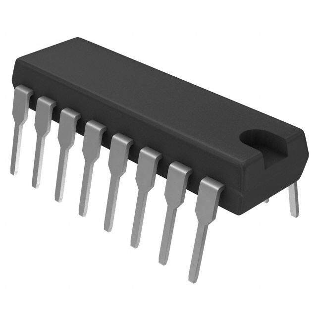
| 产品图片 |
|
| 产品型号 | SN65LVDT14QPWREP |
| rohs | 无铅 / 符合限制有害物质指令(RoHS)规范要求 |
| 产品系列 | 65LVDT |
| 产品目录页面 | |
| 供应商器件封装 | 20-TSSOP |
| 其它名称 | 296-19499-1 |
| 包装 | 剪切带 (CT) |
| 协议 | LVDS |
| 双工 | 半 |
| 安装类型 | 表面贴装 |
| 封装/外壳 | 20-TSSOP(0.173",4.40mm 宽) |
| 工作温度 | -40°C ~ 85°C |
| 接收器滞后 | - |
| 数据速率 | 125Mbps |
| 标准包装 | 1 |
| 电压-电源 | 3 V ~ 3.6 V |
| 类型 | 收发器 |
| 驱动器/接收器数 | 1/4 |





- 商务部:美国ITC正式对集成电路等产品启动337调查
- 曝三星4nm工艺存在良率问题 高通将骁龙8 Gen1或转产台积电
- 太阳诱电将投资9.5亿元在常州建新厂生产MLCC 预计2023年完工
- 英特尔发布欧洲新工厂建设计划 深化IDM 2.0 战略
- 台积电先进制程称霸业界 有大客户加持明年业绩稳了
- 达到5530亿美元!SIA预计今年全球半导体销售额将创下新高
- 英特尔拟将自动驾驶子公司Mobileye上市 估值或超500亿美元
- 三星加码芯片和SET,合并消费电子和移动部门,撤换高东真等 CEO
- 三星电子宣布重大人事变动 还合并消费电子和移动部门
- 海关总署:前11个月进口集成电路产品价值2.52万亿元 增长14.8%


PDF Datasheet 数据手册内容提取
SN65LVDT14-EP, SN65LVDT41-EP www.ti.com SCES633–JUNE2005 Memory Stick™ INTERCONNECT EXTENDER CHIPSET WITH LVDS SN65LVDT14 – ONE DRIVER PLUS FOUR RECEIVERS SN65LVDT41 – FOUR DRIVERS PLUS ONE RECEIVER FEATURES APPLICATIONS • ControlledBaseline • MemoryStick™InterfaceExtensionsWith LongInterconnectsBetweenHostand – OneAssembly/TestSite,OneFabrication MemoryStick Site • SerialPeripheralInterface™(SPI™)Interface • EnhancedDiminishingManufacturing ExtensiontoAllowLongInterconnects Sources(DMS)Support BetweenMasterandSlave • EnhancedProduct-ChangeNotification • MultiMediaCard™(MMC)InterfaceinSPI • QualificationPedigree (1) Mode • Integrated110-W NominalReceiverLine • General-PurposeAsymmetricBidirectional TerminationResistor Communication • OperateFromaSingle3.3-VSupply DESCRIPTION • GreaterThan125-MbpsDataRate • Flow-ThroughPinout The SN65LVDT14 combines one LVDS line driver with four terminated LVDS line receivers in one • LVTTL-CompatibleLogicI/Os package. It is designed to be used at the Memory • ESDProtectiononBusPinsExceeds12kV Stick™ end of an LVDS-based Memory Stick • MeetorExceedRequirementsof interfaceextension. ANSI/TIA/EIA-644AStandardforLVDS The SN65LVDT41 combines four LVDS line drivers • 20-PinThinShrinkSmall-Outline with a single terminated LVDS line receiver in one package. It is designed to be used at the host end of Package(PW)With26-MilTerminalPitch an LVDS-based Memory Stick interface extension. (1) ComponentqualificationinaccordancewithJEDECand industrystandardstoensurereliableoperationoveran brk extendedtemperaturerange.Thisincludes,butisnotlimited brk to,HighlyAcceleratedStressTest(HAST)orbiased85/85, temperaturecycle,autoclaveorunbiasedHAST, electromigration,bondintermetalliclife,andmoldcompound life.Suchqualificationtestingshouldnotbeviewedas justifyinguseofthiscomponentbeyondspecified performanceandenvironmentallimits. Pleasebeawarethatanimportantnoticeconcerningavailability,standardwarranty,anduseincriticalapplicationsofTexas Instrumentssemiconductorproductsanddisclaimerstheretoappearsattheendofthisdatasheet. SerialPeripheralInterface,SPIaretrademarksofMotorola. MultiMediaCardisatrademarkofMultiMediaCardAssociation. MemoryStickisatrademarkofSony. PRODUCTIONDATAinformationiscurrentasofpublicationdate. Copyright©2005,TexasInstrumentsIncorporated Products conform to specifications per the terms of the Texas On products compliant to MIL-PRF-38535, all parameters are Instruments standard warranty. Production processing does not testedunlessotherwisenoted.Onallotherproducts,production necessarilyincludetestingofallparameters. processingdoesnotnecessarilyincludetestingofallparameters.
SN65LVDT14-EP, SN65LVDT41-EP www.ti.com SCES633–JUNE2005 SN65LVDT41LOGICDIAGRAM SN65LVDT14LOGICDIAGRAM (POSITIVELOGIC) (POSITIVELOGIC) 1Y 1A 1D 1R 1Z 1B 2Y 2A 2D 2R 2Z 2B 3Y 3A 3D 3R 3Z 3B 4Y 4A 4D 4R 4Z 4B 5A 5Y 5R 5D 5B 5Z TYPICALMEMORYSTICKINTERFACEEXTENSION SN65LVDT41 SN65LVDT14 1Y 1A 1D SCLK 1R SCLK 1Z 1B SCLK Memory 2Y 2A Memory Stick BS 2D BS 2R BS Host SDIO 2Z 2B Stick Controller 3Y 3A SDIO DIR 3D DIR 3R 3Z 3B 4Y 4A 4D SD1 4R CBT 4Z 4B 5A 5Y CBT 5R SD2 5D 5B 5Z Absolute Maximum Ratings(1) overoperatingfree-airtemperaturerange(unlessotherwisenoted) SN65LVDT14, SN65LVDT41 UNIT MIN MAX V Supplyvoltagerange(2) –0.5 4 V CC DorR –0.5 6 Inputvoltagerange V A,B,Y,orZ –0.5 4 A,B,Y,Z,andGND – 12 Human-BodyModel(3) KV Electrostaticdischarge Allpins – 8 Charged-DeviceModel(4) Allpins – 500 V Continuoustotalpowerdissipation SeeDissipationRatingTable Storagetemperaturerange –65 150 (cid:176) C Leadtemperature1,6mm(1/16in)fromcasefor10s 260 (cid:176) C (1) Stressesbeyondthoselistedunder"absolutemaximumratings"maycausepermanentdamagetothedevice.Thesearestressratings only,andfunctionaloperationofthedeviceattheseoranyotherconditionsbeyondthoseindicatedunder"recommendedoperating conditions"isnotimplied.Exposuretoabsolute-maximum-ratedconditionsforextendedperiodsmayaffectdevicereliability. (2) Allvoltagevalues,exceptdifferentialI/Obusvoltages,arewithrespecttonetworkgroundterminal. (3) TestedinaccordancewithJEDECStandard22,TestMethodA114-A (4) TestedinaccordancewithJEDECStandard22,TestMethodC101 2
SN65LVDT14-EP, SN65LVDT41-EP www.ti.com SCES633–JUNE2005 Package Dissipation Ratings T <25(cid:176) C OPERATINGFACTOR T =85(cid:176) C T =125(cid:176) C PACKAGE POWAERRATING ABOVET =25(cid:176) C POWAERRATING POWAERRATING A PW 774mW 6.2mW/(cid:176) C 402mW 154mW Recommended Operating Conditions MIN NOM MAX UNIT V Supplyvoltagerange 3 3.3 3.6 V CC V High-levelinputvoltage 2 V IH V Low-levelinputvoltage 0.8 V IL |V | Magnitudeofdifferentialinputvoltage 0.1 0.6 V ID |VID| 2.4(cid:1)|VID| V Common-modeinputvoltage(seeFigure1) 2 2 V IC V –0.8 CC T Operatingfree-airtemperature –40 125 (cid:176) C A COMMON-MODE INPUT VOLTAGE vs DIFFERENTIAL INPUT VOLTAGE 2.5 Max at VCC > 3.15 V V Max at VCC = 3 V − 2 e g a olt V ut 1.5 p n e I d o M 1 n- o m m o C 0.5 − C Minimum VI 0 0 0.1 0.2 0.3 0.4 0.5 0.6 |VID| − Differential Input Voltage − V Figure1.V vsV andV IC ID CC 3
SN65LVDT14-EP, SN65LVDT41-EP www.ti.com SCES633–JUNE2005 Receiver Electrical Characteristics overoperatingfree-airtemperaturerange(unlessotherwisenoted) PARAMETER TESTCONDITIONS MIN TYP(1) MAX UNIT V Positive-goingdifferentialinputvoltagethreshold SeeFigure2andTable1 100 mV ITH+ V Negative-goingdifferentialinputvoltagethreshold SeeFigure2andTable1 –100 mV ITH– V High-leveloutputvoltage I =–8mA 2.4 V OH OH V Low-leveloutputvoltage I =8mA 0.4 V OL OL I Inputcurrent(AorBinputs) VI=0VandVI=2.4V, – 40 m A I Otherinputopen I Power-offinputcurrent(AorBinputs) V =0V,V =2.4V – 40 m A I(OFF) CC I C Inputcapacitance,AorBinputtoGND V =Asin2p ft+CV 5 pF i I Z Terminationimpedance V =0.4sin2.5E09tV 88 132 W t ID (1) Alltypicalvaluesareat25(cid:176) Candwitha3.3-Vsupply. Driver Electrical Characteristics overoperatingfree-airtemperaturerange(unlessotherwisenoted) PARAMETER TESTCONDITIONS MIN TYP(1) MAX UNIT R =100W , |V | Differentialoutputvoltagemagnitude L 247 340 454 mV OD SeeFigure3andFigure5 D |V | Changeindifferentialoutputvoltagemagnitude RL=100W , –50 50 mV OD betweenlogicstates SeeFigure3andFigure5 V Steady-statecommon-modeoutputvoltage SeeFigure6 1.125 1.375 V OC(SS) D V Changeinsteady-statecommon-modeoutputvoltage SeeFigure6 –50 50 mV OC(SS) betweenlogicstates V Peak-to-peakcommon-modeoutputvoltage SeeFigure6 50 mV OC(PP) I High-levelinputcurrent V =2V 20 m A IH IH I Low-levelinputcurrent V =0.8V 10 m A IL IL V orV =0V – 24 OY OZ I Short-circuitoutputcurrent mA OS V =0V(2) – 12 OD I Power-offoutputcurrent V =1.5V,V =2.4V – 1 m A O(OFF) CC O (1) Alltypicalvaluesareat25(cid:176) Candwitha3.3-Vsupply. (2) ThisparameterisGBDoverindustrialtemperaturerange. Device Electrical Characteristics overoperatingfree-airtemperaturerange(unlessotherwisenoted) PARAMETER TESTCONDITIONS MIN MAX UNIT SN65LVDT14 DriverR =100W ,DriverV =0.8Vor2V, 25 ICC Supplycurrent SN65LVDT41 ReceiverLVI=– 0.4V I 35 mA 4
SN65LVDT14-EP, SN65LVDT41-EP www.ti.com SCES633–JUNE2005 Receiver Switching Characteristics overoperatingfree-airtemperaturerange(unlessotherwisenoted) PARAMETER TESTCONDITIONS MIN NOM MAX UNIT t Propagationdelaytime,low-tohigh-leveloutput 1 2.6 4.8 ns PLH t Propagationdelaytime,high-tolow-leveloutput 1 2.6 4.8 ns PHL t Outputsignalrisetime 0.15 1.4 ns r t Outputsignalfalltime C =10pF,SeeFigure4 0.15 1.4 ns f L t Pulseskew(|t –t |) 150 750 ps sk(p) PHL PLH t Outputskew(1) 100 550 ps sk(o) t Part-to-partskew(2) 1 ns sk(pp) (1) t isthemagnitudeofthetimedifferencebetweenthet ort ofallthereceiversofasingledevicewithalloftheirinputs sk(o) PLH PHL connectedtogether. (2) t isthemagnitudeofthedifferenceinpropagationdelaytimesbetweenanyspecifiedterminalsoftwodeviceswhenbothdevices sk(pp) operatewiththesamesupplyvoltages,atthesametemperature,andhaveidenticalpackagesandtestcircuits. Driver Switching Characteristics overoperatingfree-airtemperaturerange(unlessotherwisenoted) PARAMETER TESTCONDITIONS MIN NOM MAX UNIT t Propagationdelaytime,low-tohigh-leveloutput 0.9 1.7 3.9 ns PLH t Propagationdelaytime,high-tolow-leveloutput 0.9 1.6 3.9 ns PHL t Differentialoutputsignalrisetime 0.26 1.2 ns r R =100W ,C =10pF, t Differentialoutputsignalfalltime L L 0.26 1.2 ns f SeeFigure7 t Pulseskew(|t –t |) 150 750 ps sk(p) PHL PLH t Outputskew(1) 80 400 ps sk(o) t Part-to-partskew(2) 1.5 ns sk(pp) (1) t isthemagnitudeofthetimedifferencebetweenthehigh-to-lowandlow-to-highpropagationdelaytimesatanoutput. sk(p) (2) t isthemagnitudeofthedifferenceinpropagationdelaytimesbetweenanyspecifiedterminalsoftwodeviceswhenbothdevices sk(pp) operatewiththesamesupplyvoltages,atthesametemperature,andhaveidenticalpackagesandtestcircuits. 5
SN65LVDT14-EP, SN65LVDT41-EP www.ti.com SCES633–JUNE2005 PARAMETER MEASUREMENT INFORMATION A VIA(cid:1)VIB R 2 VID VIA VIC B VO VIB Figure2.ReceiverVoltageDefinitions Table1.ReceiverMinimumandMaximumInputThresholdTestVoltages RESULTING RESULTING APPLIEDVOLTAGE DIFFERENTIAL COMMON-MODE INPUTVOLTAGE INPUTVOLTAGE V V V V IA IB ID IC 1.25V 1.15V 100mV 1.2V 1.15V 1.25V –100mV 1.2V 2.4V 2.3V 100mV 2.35V 2.3V 2.4V –100mV 2.35V 0.1V 0V 100mV 0.05V 0V 0.1V –100mV 0.05V 1.5V 0.9V 600mV 1.2V 0.9V 1.5V –600mV 1.2V 2.4V 1.8V 600mV 2.1V 1.8V 2.4V –600mV 2.1V 0.6V 0V 600mV 0.3V 0V 0.6V –600mV 0.3V IOY II Y D VOD V (cid:1)V Z IOZ VOY OY 2 OZ VI VOC VOZ Figure3.DriverVoltageandCurrentDefinitions 6
SN65LVDT14-EP, SN65LVDT41-EP www.ti.com SCES633–JUNE2005 PARAMETER MEASUREMENT INFORMATION VID VIA CL VO VIB 10 pF VIA 1.4 V VIB 1 V VID 0.4 V 0 V −0.4 V tPHL tPLH VO VOH 80% VCC/2 20% VOL tf tr A. All input pulses are supplied by a generator having the following characteristics: t or t £ 1 ns, pulse repetition rate r f (PRR)=1Mpps,pulsewidth=0.5– 0.05m s.C includesinstrumentationandfixturecapacitancewithin0,06mmof L theD.U.T. Figure4.ReceiverTimingTestCircuitandWaveforms 7
SN65LVDT14-EP, SN65LVDT41-EP www.ti.com SCES633–JUNE2005 PARAMETER MEASUREMENT INFORMATION 3.75 kW Y Input VOD 100 W _+ 0 V ≤ Vtest ≤ 2.4 V Z 3.75 kW Figure5.DriverVDOTestCircuit 49.9 W , ±1% (2 Places) Y 3 V D Input VIA 0 V Z 2 pF VOC VOC(PP) VOC(SS) VOC A. All input pulses are supplied by a generator having the following characteristics: t or t £ 1 ns, pulse repetition rate r f (PRR)=0.5Mpps,pulsewidth=500– 10m s.C includesinstrumentationandfixturecapacitancewithin0,06mmof L theD.U.T.ThemeasurementofV ismadeontestequipmentwitha–3-dBbandwidthofatleast1GHz. OC(PP) Figure6.TestCircuitandDefinitionsforDriverCommon-ModeOutputVoltage Y 100 W Input VOD ±1% Z CL (2 Places) 2 V Input 1.4 V 0.8 V tPLH tPHL 100% 80% Output VOD(H) 0 V VOD(L) 20% 0% tf tr A. All input pulses are supplied by a generator having the following characteristics: t or t £ 1 ns, pulse repetition rate r f (PRR)=1Mpps,pulsewidth=0.5– 0.05m s.C includesinstrumentationandfixturecapacitancewithin0,06mmof L theD.U.T. Figure7.TestCircuit,Timing,andVoltageDefinitionsforDifferentialOutputSignal 8
SN65LVDT14-EP, SN65LVDT41-EP www.ti.com SCES633–JUNE2005 SN65LVDT41 (Marked as LVDT41) SN65LVDT14 (Marked as LVDT14) 1D 1 20 1Y 1A 1 20 1R GND 2 19 1Z 1B 2 19 GND 2D 3 18 2Y 2A 3 18 2R V 4 17 2Z 2B 4 17 V CC CC 3D 5 16 3Y 3A 5 16 3R GND 6 15 3Z 3B 6 15 GND 4D 7 14 4Y 4A 7 14 4R V 8 13 4Z 4B 8 13 V CC CC 5R 9 12 5A 5Y 9 12 5D GND 10 11 5B 5Z 10 11 GND FUNCTION TABLES RECEIVER(1) INPUTS OUTPUT V =V –V R ID A B V ‡ 100mV H ID –100mV<V <100mV ? ID V £ –100mV L ID Open H (1) H=highlevel,L=lowlevel, ?=indeterminate DRIVER(1) INPUT OUTPUTS D Y Z H H L L L H Open L H (1) H=highlevel,L=lowlevel 9
SN65LVDT14-EP, SN65LVDT41-EP www.ti.com SCES633–JUNE2005 RECEIVER EQUIVALENT INPUT AND OUTPUT SCHEMATIC DIAGRAMS 110 W VCC VCC A B 300 kW 300 kW 5 W A Input B Input R Output 7 V 7 V 7 V DRIVER EQUIVALENT INPUT AND OUTPUT SCHEMATIC DIAGRAMS VCC VCC 50 W D Input 5 W 10 kW Y or Z Output 7 V 300 kW 7 V 10
SN65LVDT14-EP, SN65LVDT41-EP www.ti.com SCES633–JUNE2005 TYPICAL CHARACTERISTICS Receiver HIGH-LEVEL OUTPUT VOLTAGE LOW-LEVEL OUTPUT VOLTAGE vs vs HIGH-LEVEL OUTPUT CURRENT LOW-LEVEL OUTPUT CURRENT 4 5 TA = 25°C, 4.5 TA = 25°C, 3.5 VCC = 3.3 V VCC = 3.3 V V V − − 4 e 3 e g g a a 3.5 olt olt V 2.5 V ut ut 3 p p Out 2 Out 2.5 el el ev ev 2 L 1.5 L h- w- g o 1.5 − Hi 1 − L H L 1 O O V 0.5 V 0.5 0 0 −70 −60 −50 −40 −30 −20 −10 0 0 10 20 30 40 50 60 70 80 IOH − High-Level Output Current − mA IOL − Low-Level Output Current − mA Figure8. Figure9. LOW-TO-HIGH PROPAGATION DELAY TIME LOW-TO-HIGH PROPAGATION DELAY TIME vs vs FREE-AIR TEMPERATURE FREE-AIR TEMPERATURE s 3 s 3 n n − − e e m 2.9 m 2.9 y Ti VCC = 3 V y Ti VCC = 3 V a a el 2.8 el 2.8 D D n VCC = 3.3 V n VCC = 3.3 V o o ati 2.7 ati 2.7 g g a a p p o 2.6 o 2.6 r r P P High 2.5 VCC = 3.6 V High 2.5 VCC = 3.6 V o- o- T T w- 2.4 w- 2.4 o o L L − − H 2.3 H 2.3 L L P P t t 2.2 2.2 −50 −25 0 25 50 75 100 −50 −25 0 25 50 75 100 TA − Free-Air Temperature − °C TA − Free-Air Temperature − °C Figure10. Figure11. 11
SN65LVDT14-EP, SN65LVDT41-EP www.ti.com SCES633–JUNE2005 TYPICAL CHARACTERISTICS Driver LOW-TO-HIGH PROPAGATION DELAY TIME HIGH-TO-LOW PROPAGATION DELAY TIME vs vs FREE-AIR TEMPERATURE FREE-AIR TEMPERATURE s 2.1 2.2 n s me − e − n ay Ti 2 VCC = 3 V y Tim 2.1 VCC = 3 V n Del 1.9 n Dela 2 atio atio 1.9 VCC = 3.3 V g g a a p 1.8 p o o h Pr VCC = 3.6 V w Pr 1.8 Hig 1.7 Lo To- To- 1.7 Low- 1.6 High- VCC = 3.6 V − − 1.6 LH VCC = 3.3 V HL P P t 1.5 t 1.5 −50 −25 0 25 50 75 100 −50 −25 0 25 50 75 100 TA − Free-Air Temperature − °C Ta − Free-Air Temperature − °C Figure12. Figure13. 12
SN65LVDT14-EP, SN65LVDT41-EP www.ti.com SCES633–JUNE2005 APPLICATION INFORMATION bbbbrk Extending the Memory Stick Interface Using LVDS Signaling Over Differential Transmission Cables SN65LVDT41 SN65LVDT14 1Y 1A 1D SCLK 1R SCLK 1Z 1B SCLK Memory 2Y 2A Memory Stick BS 2D BS 2R BS Stick Host SDIO 2Z 2B Controller 3Y 3A SDIO DIR 3D DIR 3R 3Z 3B 4Y 4A 4D SD1 4R CBT 4Z 4B 5A 5Y CBT 5R SD2 5D 5B 5Z Figure14.System-LevelBlockDiagram LVDS, as specified by the TIA/EIA-644-A standard, The Memory Stick signaling interface operates in a provides several benefits when compared to master-slave architecture, with three active signal alternative long-distance signaling technologies: low lines. The host (master) supplies a clock (SCLK) and radiated emissions, high noise immunity, low power bus-state (BS) signal to control the operation of the consumption,andinexpensiveinterconnectcables. system. The SCLK and BS signals are unidirectional (simplex) from the host to the Memory Stick. The This device pair provides the necessary LVDS drivers serialdatainput/output(SDIO)signalisabidirectional and receivers specifically targeted at implementing a (half-duplex) signal used to communicate both control Memory Stick interconnect extension. It utilizes and data information between the host and the simplex links for the SCLK and BS signals and two Memory Stick. The direction of data control is simplex links for the SDIO data. The half-duplex managed by the host through a combination of BS SDIO data is split into two simplex streams under line states and control information delivered to the control of the host processor by means of the MemoryStick. direction (DIR) signal. The DIR signal also is carried fromthehosttotheMemoryStick on a simplex LVDS The basic Memory Stick interface is capable of link. operating only over short distances due to the single-ended nature of the digital I/O signals. Such a The switching of the SDIO signal-flow direction in the configuration is entirely suitable for compact and single-ended interfaces is managed by electronic portable devices where there is little if any separation switch devices, identified by the CBT symbol in between the host and the Memory Stick. In Figure 7. A suggested CBT device for this application applications where a greater distance is needed is the TI SN74CBTLV1G125. These devices are between the host controller and the Memory Stick, it available in space-saving SOT-23 or SC-70 is necessary to utilize a different signaling method, packages. such as low-voltage differential signaling, or LVDS. 13
SN65LVDT14-EP, SN65LVDT41-EP www.ti.com SCES633–JUNE2005 MECHANICAL DATA PW (R-PDSO-G**) PLASTIC SMALL-OUTLINE PACKAGE 14 PINS SHOWN 0,30 0,65 0,10 M 0,19 14 8 0,15 NOM 4,50 6,60 4,30 6,20 Gage Plane 0,25 1 7 0°−(cid:1)8° A 0,75 0,50 Seating Plane 1,20 MAX 0,15 0,10 0,05 PINS ** 8 14 16 20 24 28 DIM A MAX 3,10 5,10 5,10 6,60 7,90 9,80 A MIN 2,90 4,90 4,90 6,40 7,70 9,60 4040064/F 01/97 A. Alllineardimensionsareinmillimeters. B. Thisdrawingissubjecttochangewithoutnotice. C. Bodydimensionsdonotincludemoldflashorprotrusionnottoexceed0,15. D. FallswithinJEDECMO-153 14
PACKAGE MATERIALS INFORMATION www.ti.com 26-Jan-2013 TAPE AND REEL INFORMATION *Alldimensionsarenominal Device Package Package Pins SPQ Reel Reel A0 B0 K0 P1 W Pin1 Type Drawing Diameter Width (mm) (mm) (mm) (mm) (mm) Quadrant (mm) W1(mm) SN65LVDT14QPWREP TSSOP PW 20 2000 330.0 16.4 6.95 7.1 1.6 8.0 16.0 Q1 SN65LVDT41QPWREP TSSOP PW 20 2000 330.0 16.4 6.95 7.1 1.6 8.0 16.0 Q1 PackMaterials-Page1
PACKAGE MATERIALS INFORMATION www.ti.com 26-Jan-2013 *Alldimensionsarenominal Device PackageType PackageDrawing Pins SPQ Length(mm) Width(mm) Height(mm) SN65LVDT14QPWREP TSSOP PW 20 2000 367.0 367.0 38.0 SN65LVDT41QPWREP TSSOP PW 20 2000 367.0 367.0 38.0 PackMaterials-Page2
None
None
IMPORTANTNOTICE TexasInstrumentsIncorporatedanditssubsidiaries(TI)reservetherighttomakecorrections,enhancements,improvementsandother changestoitssemiconductorproductsandservicesperJESD46,latestissue,andtodiscontinueanyproductorserviceperJESD48,latest issue.Buyersshouldobtainthelatestrelevantinformationbeforeplacingordersandshouldverifythatsuchinformationiscurrentand complete.Allsemiconductorproducts(alsoreferredtohereinas“components”)aresoldsubjecttoTI’stermsandconditionsofsale suppliedatthetimeoforderacknowledgment. TIwarrantsperformanceofitscomponentstothespecificationsapplicableatthetimeofsale,inaccordancewiththewarrantyinTI’sterms andconditionsofsaleofsemiconductorproducts.TestingandotherqualitycontroltechniquesareusedtotheextentTIdeemsnecessary tosupportthiswarranty.Exceptwheremandatedbyapplicablelaw,testingofallparametersofeachcomponentisnotnecessarily performed. TIassumesnoliabilityforapplicationsassistanceorthedesignofBuyers’products.Buyersareresponsiblefortheirproductsand applicationsusingTIcomponents.TominimizetherisksassociatedwithBuyers’productsandapplications,Buyersshouldprovide adequatedesignandoperatingsafeguards. TIdoesnotwarrantorrepresentthatanylicense,eitherexpressorimplied,isgrantedunderanypatentright,copyright,maskworkright,or otherintellectualpropertyrightrelatingtoanycombination,machine,orprocessinwhichTIcomponentsorservicesareused.Information publishedbyTIregardingthird-partyproductsorservicesdoesnotconstitutealicensetousesuchproductsorservicesorawarrantyor endorsementthereof.Useofsuchinformationmayrequirealicensefromathirdpartyunderthepatentsorotherintellectualpropertyofthe thirdparty,oralicensefromTIunderthepatentsorotherintellectualpropertyofTI. ReproductionofsignificantportionsofTIinformationinTIdatabooksordatasheetsispermissibleonlyifreproductioniswithoutalteration andisaccompaniedbyallassociatedwarranties,conditions,limitations,andnotices.TIisnotresponsibleorliableforsuchaltered documentation.Informationofthirdpartiesmaybesubjecttoadditionalrestrictions. ResaleofTIcomponentsorserviceswithstatementsdifferentfromorbeyondtheparametersstatedbyTIforthatcomponentorservice voidsallexpressandanyimpliedwarrantiesfortheassociatedTIcomponentorserviceandisanunfairanddeceptivebusinesspractice. TIisnotresponsibleorliableforanysuchstatements. Buyeracknowledgesandagreesthatitissolelyresponsibleforcompliancewithalllegal,regulatoryandsafety-relatedrequirements concerningitsproducts,andanyuseofTIcomponentsinitsapplications,notwithstandinganyapplications-relatedinformationorsupport thatmaybeprovidedbyTI.Buyerrepresentsandagreesthatithasallthenecessaryexpertisetocreateandimplementsafeguardswhich anticipatedangerousconsequencesoffailures,monitorfailuresandtheirconsequences,lessenthelikelihoodoffailuresthatmightcause harmandtakeappropriateremedialactions.BuyerwillfullyindemnifyTIanditsrepresentativesagainstanydamagesarisingoutoftheuse ofanyTIcomponentsinsafety-criticalapplications. Insomecases,TIcomponentsmaybepromotedspecificallytofacilitatesafety-relatedapplications.Withsuchcomponents,TI’sgoalisto helpenablecustomerstodesignandcreatetheirownend-productsolutionsthatmeetapplicablefunctionalsafetystandardsand requirements.Nonetheless,suchcomponentsaresubjecttotheseterms. NoTIcomponentsareauthorizedforuseinFDAClassIII(orsimilarlife-criticalmedicalequipment)unlessauthorizedofficersoftheparties haveexecutedaspecialagreementspecificallygoverningsuchuse. OnlythoseTIcomponentswhichTIhasspecificallydesignatedasmilitarygradeor“enhancedplastic”aredesignedandintendedforusein military/aerospaceapplicationsorenvironments.BuyeracknowledgesandagreesthatanymilitaryoraerospaceuseofTIcomponents whichhavenotbeensodesignatedissolelyattheBuyer'srisk,andthatBuyerissolelyresponsibleforcompliancewithalllegaland regulatoryrequirementsinconnectionwithsuchuse. TIhasspecificallydesignatedcertaincomponentsasmeetingISO/TS16949requirements,mainlyforautomotiveuse.Inanycaseofuseof non-designatedproducts,TIwillnotberesponsibleforanyfailuretomeetISO/TS16949. Products Applications Audio www.ti.com/audio AutomotiveandTransportation www.ti.com/automotive Amplifiers amplifier.ti.com CommunicationsandTelecom www.ti.com/communications DataConverters dataconverter.ti.com ComputersandPeripherals www.ti.com/computers DLP®Products www.dlp.com ConsumerElectronics www.ti.com/consumer-apps DSP dsp.ti.com EnergyandLighting www.ti.com/energy ClocksandTimers www.ti.com/clocks Industrial www.ti.com/industrial Interface interface.ti.com Medical www.ti.com/medical Logic logic.ti.com Security www.ti.com/security PowerMgmt power.ti.com Space,AvionicsandDefense www.ti.com/space-avionics-defense Microcontrollers microcontroller.ti.com VideoandImaging www.ti.com/video RFID www.ti-rfid.com OMAPApplicationsProcessors www.ti.com/omap TIE2ECommunity e2e.ti.com WirelessConnectivity www.ti.com/wirelessconnectivity MailingAddress:TexasInstruments,PostOfficeBox655303,Dallas,Texas75265 Copyright©2015,TexasInstrumentsIncorporated

 Datasheet下载
