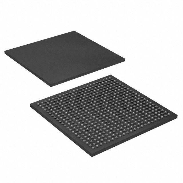
ICGOO在线商城 > SN65HVD96EVM
- 型号: SN65HVD96EVM
- 制造商: Texas Instruments
- 库位|库存: xxxx|xxxx
- 要求:
| 数量阶梯 | 香港交货 | 国内含税 |
| +xxxx | $xxxx | ¥xxxx |
查看当月历史价格
查看今年历史价格
SN65HVD96EVM产品简介:
ICGOO电子元器件商城为您提供SN65HVD96EVM由Texas Instruments设计生产,在icgoo商城现货销售,并且可以通过原厂、代理商等渠道进行代购。 提供SN65HVD96EVM价格参考以及Texas InstrumentsSN65HVD96EVM封装/规格参数等产品信息。 你可以下载SN65HVD96EVM参考资料、Datasheet数据手册功能说明书, 资料中有SN65HVD96EVM详细功能的应用电路图电压和使用方法及教程。
| 参数 | 数值 |
| 产品目录 | 编程器,开发系统嵌入式解决方案 |
| 描述 | EVAL MODULE FOR SN65HVD96界面开发工具 SN65HVD96 Eval Mod |
| 产品分类 | |
| 品牌 | Texas Instruments |
| 产品手册 | |
| 产品图片 |
|
| rohs | 否无铅 / 符合限制有害物质指令(RoHS)规范要求 |
| 产品系列 | 模拟与数字IC开发工具,界面开发工具,Texas Instruments SN65HVD96EVMSymPol™ |
| 数据手册 | http://www.ti.com/lit/pdf/sllu128http://www.ti.com/lit/pdf/sllse35ahttp://www.ti.com/lit/pdf/slyb174 |
| 产品型号 | SN65HVD96EVM |
| 主要属性 | - |
| 主要用途 | 接口,收发器 |
| 产品 | Evaluation Modules |
| 产品种类 | 界面开发工具 |
| 使用的IC/零件 | SN65HVD96 |
| 其它名称 | 296-30982 |
| 制造商产品页 | http://www.ti.com/general/docs/suppproductinfo.tsp?distId=10&orderablePartNumber=SN65HVD96EVM |
| 商标 | Texas Instruments |
| 嵌入式 | - |
| 工作电源电压 | 5 V |
| 工具用于评估 | SN65HVD96 |
| 工厂包装数量 | 1 |
| 所含物品 | 板 |
| 接口类型 | RS-485 |
| 标准包装 | 1 |
| 类型 | RS-485 |
| 辅助属性 | - |
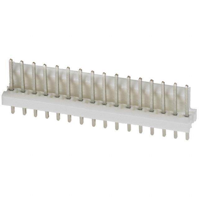
.jpg)

PDF Datasheet 数据手册内容提取
User's Guide SLLU128A–June2010–RevisedAugust2010 Sympol™ Transceiver This manual describes the SN65HVD96 Evaluation Module (EVM). This EVM helps designers evaluate the device performance under wire-fault and common-mode conditions, thus supporting the fast developmentandanalysisofdatatransmissionsystemsusingSN65HVD96transceivers. Contents 1 Overview ..................................................................................................................... 2 2 EVMSet-upandPrecautions ............................................................................................. 2 3 PoweringuptheEVMandTakingMeasurements ..................................................................... 4 3.1 MeasurementExamples .......................................................................................... 4 ListofFigures 1 BlockDiagramandSympol™SignalStates............................................................................ 2 2 EVMSchematic............................................................................................................. 3 3 BridgingDUT_GNDwithEART_GND.................................................................................... 3 4 ExampleforStimulusandProbePointswithJMP4andJMP14 ..................................................... 4 5 TransceiverConfigurationforNormalOperation....................................................................... 5 6 EVMSet-upforNormalTransceiverOperation......................................................................... 5 7 ConfigurationforMaximumLoading...................................................................................... 6 8 EVMSet-upforMaximumLoading....................................................................................... 6 9 Wire-faultSimulationUsingtwoEVMs................................................................................... 7 10 EVMConfigurations:LeftasReceiverEVM,RightasTransmitterEVM............................................ 7 11 Sympol™Signalingat500kbpsOver1MeterCable ................................................................. 8 12 Sympol™SignalingisUnaffectedbyCommon-ModeVoltage....................................................... 8 13 Sympol™SignalingisUnaffectedbyCross-wireFault................................................................ 8 14 TopViewofSN65HVD96EVM.......................................................................................... 9 15 BottomViewofSN65HVD96EVM ...................................................................................... 9 SympolisatrademarkofTexasInstruments. SLLU128A–June2010–RevisedAugust2010 Sympol™Transceiver 1 Copyright©2010,TexasInstrumentsIncorporated
Overview www.ti.com 1 Overview TheSN65HVD96isdesignedforerror-freedatatransmissionunderwire-faultconditions.Thereceiver providescorrectoutputdatawhetherthebuswiresareconnectednormallyorcross-wired.Thisfeatureis knownassymmetric-polarity(Sympol™)andisauto-detectedinternally,sonointerventionfromthe controllerortheoperatorisrequired(seeFigure1). Driver signaling(DE= high) Receiver detecting(RE=low) SN65HVD96 D Aor B 1 8 R VCC VCM |VOD| < 0.5V |VOD| > 0.9V B orA RE 2 7 B B 3 6 VCM |VOD| < 0.5V |VOD| > 0.9V DE A A |VID| passive active 4 5 D GND |VOD| passive active R Figure1.BlockDiagramandSympol™SignalStates Figure1showsthatSympol™signalingissimilarbutnotidenticaltoCAN-bussignaling.Sympol™ transceiversonlylookatthemagnitudeofthedifferentialbusvoltage,|V –V |,notitsactualpolarity.Ata A B driveroutput,thisvoltageiscalled|V |,ataremotereceiverinput,itbecomes|V |. OD ID ASympol™busstateisknownaspassivewhen|V –V |< 0.5V,anditisactivewhen|V –V |> 0.9V. A B A B SimilartoRS-485,Sympol™transceiverscanbeusedforpoint-to-point,multi-drop,ormulti-point networks.Current-limiteddifferentialoutputsprotectincaseofdrivercontentionona"party-line"bus.High receiverinputimpedanceallowstheconnectionofatleast32nodes.Thepin-outisidenticaltothe industry-standardSN75176transceiver,thusallowingforadirectupgradefromRS-485toSympol™. NotethatSympol™signalingdoesnotsupporttheoperationofSympol™transceiverstogetherwith RS-485orCANtransceiversinamixed-transceivertypeofnetwork.OnlySympol™transceiversareable tocommunicatebetweenanother.However,itispossibletoreplaceanentireRS-485transceivernetwork withSympol™transceiverswhilemaintainingthesamehigh-levelnetworkprotocolwithouttheneedfor softwarechanges. 2 EVM Set-up and Precautions Figure2showstheschematicoftheSNHVD96EVM.Theboardmounts13BergStikheadersfromJMP1 toJMP14(JMP5isomitted)andtwo3-pinterminalblocks,TB1andTB2,supportingthedeviceevaluation forawiderangeofsystemconfigurations. • Pin1(EARTH)isasecondgroundpinthatallowsapplyinganexternalvoltagebetweenGNDand EARTHtosimulatecommon-modevoltageconditions. • Pin2(GND)shallbeconnectedtothenegativeoutputorgroundterminalofthePSU.Thispin representsthegroundpotentialofthedevice-under-testandtheentireEVM.Italsoconnectsto variousjumpersontheboard. • Pin3(VCC)shallbeconnectedtothepositiveoutputofaregulated5Vpowersupplyunit(PSU)asit representsthepositivesupplyvoltageofthedevice-under-testandalsoconnectstovariousjumpers ontheboard. 2 Sympol™Transceiver SLLU128A–June2010–RevisedAugust2010 Copyright©2010,TexasInstrumentsIncorporated
www.ti.com EVMSet-upandPrecautions D3 R11 TB1 2 1 R_OUT 1kW 1 2 3 R10 VCC C1 C2 C10 C11 1mF 0.1mF 10mF 68mF R1 JMP1 0W GND 1kW 12 VCC R JMP111 C1m4F C0.51mF Cn.1a2. Cn.1a3. 1 3 2 EARTH D1 C6 VCC_ON 4 3 n.a. 2 JMP2 VCC VCM_B 1 VCC JMP12 2 RE 1 R6 34 23 R5n.02aW. 12 RRUE1 VCCB 87 C11mF R5 n.a. CB7 12JMP6 0R8W JMP712 12 TB2 JMP31 VCC JMP13 34 DDE GNDA 65 120W nA.a. 34 R9 34 3 2 DE 1 R7 0W 3 2 R3 n.a. 4 3 50W B A n.a. VCM_A M_ M_ C C JMP4 V V 1 VCC JMP14 2 D 1 3 2 R4 A 4 3 2 1 B 4 3 50W M_C JMP10 M_C n.a. VCVC VCVC 4 3 2 1 4 3 2 1 2 D2 1 R14 JMP8 JMP9 D_IN 1kW C8 C9 n.a. n.a. Figure2.EVMSchematic Forthefirstmeasurements,ignorethecommon-modesimulationandconnectEARTHtoGNDthrougha wire-bridgebetweenpin1andpin2ofTB1. PSU 5V TB1 1 2 3 Figure3.BridgingDUT_GNDwithEART_GND WhileJMP2toJMP4arestimulationpoints,orheadersthroughwhichthecontrolanddatasignalsforthe SN65HVD96areapplied,JMP1,andJMP11toJMP14areprobepoints,orheadersatwhichthesesignal canbemeasured. Notethatthe50Ω resistors,R2,R3,andR4,havetheindexn.a.,indicatingthatthesecomponentsare notassembled.Becausesignalgeneratorshaveatypicalsourceimpedanceof50Ω,theiroutputistwice therequiredsignalvoltage,assumingthattheon-board50Ω resistorsdividethisvoltagedowntothe correctsignallevel. Withouttheseresistors;however,thisvoltagedivideractionisnotgiven,andthegeneratoroutputvoltage mustbereducedto5Vtoavoiddamagingthetransceiverinputs. SLLU128A–June2010–RevisedAugust2010 Sympol™Transceiver 3 Copyright©2010,TexasInstrumentsIncorporated
PoweringuptheEVMandTakingMeasurements www.ti.com Signal Generator Scope 5V Ch1 Ch2 JMP4 1 VCC JMP14 2 1 D-inputof 3 2 SN65HVD95 4 3 Figure4.ExampleforStimulusandProbePointswithJMP4andJMP14 Figure4givesanexampleforenteringadatasignalintothedriversectionoftheSympol™transceiver. Thesignaloutputofthegeneratorisadjustedto5V.Thegenerator’sgroundterminalisconnectedwithpin 3,andthesignaloutputterminalwithpin2ofJMP4.Thedatasignalismeasuredviaanoscilloscopewith itssignalinputconnectedtopin1anditsgroundwireconnectedtopin2andofJMP14. Thesameset-upappliestotheDEandREinputsviatheircorrespondingheadersJMP2and12and JMP3and13.JMP1however,mustnotreceiveasignalstimulus.LikeJMP11,itrepresentsthereceiver output,R,oftheSN65HVD96. Insteadofusingsignalgenerators,theEVMcandirectlyinterfacetomicrocontrollerI/O.Thenthe non-assembled50Ω resistorsareofnoconcern.However,forproperoperation,itmustbeassuredthat thehigh-levelinputvoltageV ≥2Vandthelow-levelinputvoltageV ≤ 0.8V. IH IL 3 Powering up the EVM and Taking Measurements Thegenerallyrecommendedprocedurefortakingmeasurementsislisted: 1. Installthegroundconnectionsrequired. 2. Connecttheoscilloscopewiththerespectiveprobepointsyouwanttomeasure. 3. Adjustthepower-supplyto5V. 4. Adjustthegeneratoroutputsfora5Vmaximumoutputsignallevel,orcheckthelogicswitchinglevels ofthecontrollerI/O. 5. Connectthepowersupplyconductorwithpin3ofTB1andobservetheblueLED(D1)turningon. 6. ConnectsignalconductorsfromthecontrollerorthegeneratorwiththeircorrespondingEVMinputsat JMP2toJMP4. 7. Logichighatthereceiveroutput,R,willturnontheredLED(D3),andlogichighatthedriverinput,D, turnsonthegreenLED(D2).IfDisleftopen,aninternal100kΩ pull-upresistorprovideslogichigh instead.However,duetothesmallinputcurrent,D2willremainoff. 3.1 Measurement Examples Eachofthefollowingmeasurementexamplesshowstheequivalentcircuitdiagramandthecorresponding EVMset-up.Onlythemeasurementrelevantheadersandterminalblocksareshown,andnotnecessarily attheirexactlocationontheEVM. 1. StandardTransceiverConfiguration Normaltransceiveroperationrequiresboth,thedriverandthereceiversectionsbeingactive. Therefore,thereceiverenablepin(RE)mustbeatlogiclowpotentialandthedriverenablepin(DE)at logichigh. TransmitdataenteringattheD-inputterminalappearasthedifferentialoutputvoltage(V =V –V ) OD A B onthebuswires,AandB.Viatheactivereceiver,itispossibletosensethedatatrafficintransmit direction. 4 Sympol™Transceiver SLLU128A–June2010–RevisedAugust2010 Copyright©2010,TexasInstrumentsIncorporated
www.ti.com PoweringuptheEVMandTakingMeasurements DUT_VCC U1 Receive R 1 8 Vcc B R8 B data RE 2 7 B 0V 0W R5 V 5V DE 3 6 A 120W OD R9 Transmit D 4 5 GND data VB A 0W A V A Figure5.TransceiverConfigurationforNormalOperation Figure6showsthecorrespondingEVMset-up.Earthandgroundreceivethesamereferencepotential, PSU-ground,throughthewire-bridgefrompin1topin2attheterminalblock,TB1,whilepin3(VCC) isconnectedtothe5Voutputofapower-supplyunit(PSU). Signal Generator Scope PSU1 5V 5V Ch1 Ch2 Ch3 Ch4 TB1 JMP2 1 VCC JMP11 1 2 3 2 /RE 1 R H D C 3 2 RT GN VC 4 3 A E JMP3 JMP6 1 VCC HVD96 1 2 DE 2 B 3 EVM 3 A 4 4 JMP4 1 VCC JMP14 2 1 D 3 2 4 3 Figure6.EVMSet-upforNormalTransceiverOperation ThelowpotentialforREisprovidedbythewire-bridgefrompin2topin3atJMP2,andthehigh potentialforDEthroughawire-bridgefrompin2topin1atJMP3.Datafromthesignalgeneratorenter theboardatpin2andpin3ofJMP4.Thisdataismeasuredviachannel1,whichisconnectedtopin1 andpin2ofJMP14.Channel2measuresthereceivedataatJMP11,andchannels3and4thebus voltages,V andV ,atJMP6. A B 2. OperationUnderMaximumLoad EIA-485(RS-485)specifiesthreemaximumloadparameters:amaximumdifferentialloadof60Ω,a maximumcommon-modeloadof375Ω foreachbuswire,andareceivercommon-modevoltage rangefrom–7Vto+12V.Figure7reflectstheserequirementsthroughR5,R8,R9,andV .Notethat CM undermaximumloadconditionsthetransceivermustbecapableofsourcingandsinkingbuscurrents ofupto55mA.ThepurposeofthistestistoshowtherobustnessofV overtheentire OD common-modevoltagerangeatmaximumload. SLLU128A–June2010–RevisedAugust2010 Sympol™Transceiver 5 Copyright©2010,TexasInstrumentsIncorporated
PoweringuptheEVMandTakingMeasurements www.ti.com DUT_VCC U1 Receive R 1 8 Vcc B R8 data RE 2 7 B 0V 375W R5 V DE 3 6 A 60W OD 5V R9 Transmit D 4 5 GND data A 375W V =-7V to+12V CM Figure7.ConfigurationforMaximumLoading Whilethecableconnectionsofthesignalgeneratorandtheoscilloscoperemainthesameasinthe previousexample,thefollowingboardchangesneedtobeimplementedtoreflectmaximumload conditions: • replaceR5(120Ω default)with60 Ω • replaceR8andR9(0Ω default)with375Ω • connectpin2ofJMP7withpin1andpin3withpin4 • replacethepreviouswire-bridgeatTB1withasecondpowersupplyunit(PSU2)andconnectthe groundterminalsofboth,PSU1andPSU2withawire-bridge,asshowninFigure8. Signal Generator Scope PSU2 PSU1 5V Ch4 Ch3 Ch2 Ch1 VCM 5V TB1 JMP2 1 VCC JMP11 1 2 3 2 /RE 1 R H D C 3 2 RT GN VC 4 3 A E JMP3 JMP6 JMP7 R8 1 VCC HVD96 1 375W 1 2 DE 2 2 3 EVM 3 3 4 4 4 R9 375W JMP4 1 VCC JMP14 2 1 D 3 2 4 3 Figure8.EVMSet-upforMaximumLoading NotethatFigure8onlyshowsthewiringofPSU2forpositivecommon-modevoltages.Fornegative V ,connectthegroundterminalofPSU2withpin1ofTB1(Earth),andtheV -outputofPSU2with CM CM thegroundterminalofPSU1. 3. Wire-faultCondition Simulatingawire-faultconditioniseasilyaccomplishedbyusingtwoevaluationmodules,one configuredasthedriving,theotheroneasthereceivingEVM.Figure9showstheequivalentcircuit usingtwoEVMswithdefaultcomponentvalues. 6 Sympol™Transceiver SLLU128A–June2010–RevisedAugust2010 Copyright©2010,TexasInstrumentsIncorporated
www.ti.com PoweringuptheEVMandTakingMeasurements DUT_VCC DUT_VCC U1 U1 Receive R 1 8 Vcc Vcc 8 1 R data B R8 R8 B 00VV DREE 23 67 BA R1250WVOD 0RW9 0RW9 120RW5 BA 67 23 DREE 55VV D 4 5 GND A 0W 0W A GND 5 4 D Tradnastamit Figure9.Wire-faultSimulationUsingtwoEVMs Figure10illustratestheEVMconfigurationsandthemeasurementset-up.Therightevaluationmodule (EVM2)isconfiguredasthedriver.Both,driverandreceiverenableinputs,DEandRE,receivehigh potentialthroughthewire-bridgestoVCCatJMP3andJMP2.NotethatEVM2isturnedby180°. EVM1ontheleftisconfiguredasthereceiver.Here,thedriverandreceiverenableinputsreceivelow potentialthroughthewire-bridgestoGNDatJMP3andJMP2. Signal Scope PSU1 Generator 5V 5V Ch4 Ch3 Ch2 Ch1 TB1 JMP14 JMP4 JMP2 3 4 1 VCC JMP11 1 2 3 2 3 2 /RE 1 R H D C D 1 2 34 23 EART GN VC VCC 1 JMP3 JMP3 JMP6 TB2 TB2 4 1 VCC 1 1 3 A HVD96 3 23 DE BA 23 BA 23 12 B EVM2 DVECC 12 4 4 HVD96 JMP2 EVM1 4 PSU2 VCC GND EARTH /RE 23 5V VCC 1 3 2 1 TB1 Figure10.EVMConfigurations:LeftasReceiverEVM,RightasTransmitterEVM TheinputdatasignalenteringEVM2atJMP4ismeasuredonscopechannel1,probingthesignalat theD-inputpinofJMP14.Thecross-wiringofthebuswiresoccursattheEVMinterlink,betweenthe twoTB2terminalblocks.Toproofwire-faultrobustness,thedifferentialreceiverinputandthe single-endedreceiveroutputsignalsaremeasuredafterthecross-wiring.Channels2and3measure thebusvoltages,V andV ,atpin2andpin3ofJMP6,whilethereceiveroutputistakenfrompin1at A B JMP11.Notethatboth5Vpowersupplies,PSU1andPSU2havetheirgroundterminalsconnectedto thegroundandEarthterminalsoftheirrespectiveEVMs. ThescopepicturesfortheindividualexamplesareshowninFigure11,Figure12,andFigure13. Figure14andFigure15showthetopandbottomviewoftheSN65HVD96EVM. SLLU128A–June2010–RevisedAugust2010 Sympol™Transceiver 7 Copyright©2010,TexasInstrumentsIncorporated
PoweringuptheEVMandTakingMeasurements www.ti.com D 5V/Div V A V B 2V/Div R 5V/Div 1us/Div Figure11.Sympol™Signalingat500kbpsOver1MeterCable D 10V/Div 5V/Div V A V B R 5V/Div 1us/Div Figure12.Sympol™SignalingisUnaffectedbyCommon-ModeVoltage D 5V/Div V B V A 2V/Div R 5V/Div 1us/Div Figure13.Sympol™SignalingisUnaffectedbyCross-wireFault 8 Sympol™Transceiver SLLU128A–June2010–RevisedAugust2010 Copyright©2010,TexasInstrumentsIncorporated
www.ti.com PoweringuptheEVMandTakingMeasurements Figure14.TopViewofSN65HVD96EVM Figure15.BottomViewofSN65HVD96EVM FordetailedinformationonthedeviceparametersseetheSN65HVD96datasheet(Lit.#SLLSE35). SLLU128A–June2010–RevisedAugust2010 Sympol™Transceiver 9 Copyright©2010,TexasInstrumentsIncorporated
EvaluationBoard/KitImportantNotice TexasInstruments(TI)providestheenclosedproduct(s)underthefollowingconditions: Thisevaluationboard/kitisintendedforuseforENGINEERINGDEVELOPMENT,DEMONSTRATION,OREVALUATION PURPOSESONLYandisnotconsideredbyTItobeafinishedend-productfitforgeneralconsumeruse.Personshandlingthe product(s)musthaveelectronicstrainingandobservegoodengineeringpracticestandards.Assuch,thegoodsbeingprovidedare notintendedtobecompleteintermsofrequireddesign-,marketing-,and/ormanufacturing-relatedprotectiveconsiderations, includingproductsafetyandenvironmentalmeasurestypicallyfoundinendproductsthatincorporatesuchsemiconductor componentsorcircuitboards.Thisevaluationboard/kitdoesnotfallwithinthescopeoftheEuropeanUniondirectivesregarding electromagneticcompatibility,restrictedsubstances(RoHS),recycling(WEEE),FCC,CEorUL,andthereforemaynotmeetthe technicalrequirementsofthesedirectivesorotherrelateddirectives. Shouldthisevaluationboard/kitnotmeetthespecificationsindicatedintheUser’sGuide,theboard/kitmaybereturnedwithin30 daysfromthedateofdeliveryforafullrefund.THEFOREGOINGWARRANTYISTHEEXCLUSIVEWARRANTYMADEBY SELLERTOBUYERANDISINLIEUOFALLOTHERWARRANTIES,EXPRESSED,IMPLIED,ORSTATUTORY,INCLUDING ANYWARRANTYOFMERCHANTABILITYORFITNESSFORANYPARTICULARPURPOSE. Theuserassumesallresponsibilityandliabilityforproperandsafehandlingofthegoods.Further,theuserindemnifiesTIfromall claimsarisingfromthehandlingoruseofthegoods.Duetotheopenconstructionoftheproduct,itistheuser’sresponsibilityto takeanyandallappropriateprecautionswithregardtoelectrostaticdischarge. EXCEPTTOTHEEXTENTOFTHEINDEMNITYSETFORTHABOVE,NEITHERPARTYSHALLBELIABLETOTHEOTHER FORANYINDIRECT,SPECIAL,INCIDENTAL,ORCONSEQUENTIALDAMAGES. TIcurrentlydealswithavarietyofcustomersforproducts,andthereforeourarrangementwiththeuserisnotexclusive. TIassumesnoliabilityforapplicationsassistance,customerproductdesign,softwareperformance,orinfringementof patentsorservicesdescribedherein. PleasereadtheUser’sGuideand,specifically,theWarningsandRestrictionsnoticeintheUser’sGuidepriortohandlingthe product.Thisnoticecontainsimportantsafetyinformationabouttemperaturesandvoltages.ForadditionalinformationonTI’s environmentaland/orsafetyprograms,pleasecontacttheTIapplicationengineerorvisitwww.ti.com/esh. NolicenseisgrantedunderanypatentrightorotherintellectualpropertyrightofTIcoveringorrelatingtoanymachine,process,or combinationinwhichsuchTIproductsorservicesmightbeorareused. FCCWarning Thisevaluationboard/kitisintendedforuseforENGINEERINGDEVELOPMENT,DEMONSTRATION,OREVALUATION PURPOSESONLYandisnotconsideredbyTItobeafinishedend-productfitforgeneralconsumeruse.Itgenerates,uses,and canradiateradiofrequencyenergyandhasnotbeentestedforcompliancewiththelimitsofcomputingdevicespursuanttopart15 ofFCCrules,whicharedesignedtoprovidereasonableprotectionagainstradiofrequencyinterference.Operationofthis equipmentinotherenvironmentsmaycauseinterferencewithradiocommunications,inwhichcasetheuserathisownexpense willberequiredtotakewhatevermeasuresmayberequiredtocorrectthisinterference. EVMWarningsandRestrictions ItisimportanttooperatethisEVMwithintheinputvoltagerangeof0Vto5.25Vandtheoutputvoltagerangeof0Vto5.25V. Exceedingthespecifiedinputrangemaycauseunexpectedoperationand/orirreversibledamagetotheEVM.Ifthereare questionsconcerningtheinputrange,pleasecontactaTIfieldrepresentativepriortoconnectingtheinputpower. Applyingloadsoutsideofthespecifiedoutputrangemayresultinunintendedoperationand/orpossiblepermanentdamagetothe EVM.PleaseconsulttheEVMUser'sGuidepriortoconnectinganyloadtotheEVMoutput.Ifthereisuncertaintyastotheload specification,pleasecontactaTIfieldrepresentative. Duringnormaloperation,somecircuitcomponentsmayhavecasetemperaturesgreaterthan125°C.TheEVMisdesignedto operateproperlywithcertaincomponentsabove125°Caslongastheinputandoutputrangesaremaintained.Thesecomponents includebutarenotlimitedtolinearregulators,switchingtransistors,passtransistors,andcurrentsenseresistors.Thesetypesof devicescanbeidentifiedusingtheEVMschematiclocatedintheEVMUser'sGuide.Whenplacingmeasurementprobesnear thesedevicesduringoperation,pleasebeawarethatthesedevicesmaybeverywarmtothetouch. MailingAddress:TexasInstruments,PostOfficeBox655303,Dallas,Texas75265 Copyright©2010,TexasInstrumentsIncorporated
IMPORTANTNOTICE TexasInstrumentsIncorporatedanditssubsidiaries(TI)reservetherighttomakecorrections,modifications,enhancements,improvements, andotherchangestoitsproductsandservicesatanytimeandtodiscontinueanyproductorservicewithoutnotice.Customersshould obtainthelatestrelevantinformationbeforeplacingordersandshouldverifythatsuchinformationiscurrentandcomplete.Allproductsare soldsubjecttoTI’stermsandconditionsofsalesuppliedatthetimeoforderacknowledgment. TIwarrantsperformanceofitshardwareproductstothespecificationsapplicableatthetimeofsaleinaccordancewithTI’sstandard warranty.TestingandotherqualitycontroltechniquesareusedtotheextentTIdeemsnecessarytosupportthiswarranty.Exceptwhere mandatedbygovernmentrequirements,testingofallparametersofeachproductisnotnecessarilyperformed. TIassumesnoliabilityforapplicationsassistanceorcustomerproductdesign.Customersareresponsiblefortheirproductsand applicationsusingTIcomponents.Tominimizetherisksassociatedwithcustomerproductsandapplications,customersshouldprovide adequatedesignandoperatingsafeguards. TIdoesnotwarrantorrepresentthatanylicense,eitherexpressorimplied,isgrantedunderanyTIpatentright,copyright,maskworkright, orotherTIintellectualpropertyrightrelatingtoanycombination,machine,orprocessinwhichTIproductsorservicesareused.Information publishedbyTIregardingthird-partyproductsorservicesdoesnotconstitutealicensefromTItousesuchproductsorservicesora warrantyorendorsementthereof.Useofsuchinformationmayrequirealicensefromathirdpartyunderthepatentsorotherintellectual propertyofthethirdparty,oralicensefromTIunderthepatentsorotherintellectualpropertyofTI. ReproductionofTIinformationinTIdatabooksordatasheetsispermissibleonlyifreproductioniswithoutalterationandisaccompanied byallassociatedwarranties,conditions,limitations,andnotices.Reproductionofthisinformationwithalterationisanunfairanddeceptive businesspractice.TIisnotresponsibleorliableforsuchaltereddocumentation.Informationofthirdpartiesmaybesubjecttoadditional restrictions. ResaleofTIproductsorserviceswithstatementsdifferentfromorbeyondtheparametersstatedbyTIforthatproductorservicevoidsall expressandanyimpliedwarrantiesfortheassociatedTIproductorserviceandisanunfairanddeceptivebusinesspractice.TIisnot responsibleorliableforanysuchstatements. TIproductsarenotauthorizedforuseinsafety-criticalapplications(suchaslifesupport)whereafailureoftheTIproductwouldreasonably beexpectedtocauseseverepersonalinjuryordeath,unlessofficersofthepartieshaveexecutedanagreementspecificallygoverning suchuse.Buyersrepresentthattheyhaveallnecessaryexpertiseinthesafetyandregulatoryramificationsoftheirapplications,and acknowledgeandagreethattheyaresolelyresponsibleforalllegal,regulatoryandsafety-relatedrequirementsconcerningtheirproducts andanyuseofTIproductsinsuchsafety-criticalapplications,notwithstandinganyapplications-relatedinformationorsupportthatmaybe providedbyTI.Further,BuyersmustfullyindemnifyTIanditsrepresentativesagainstanydamagesarisingoutoftheuseofTIproductsin suchsafety-criticalapplications. TIproductsareneitherdesignednorintendedforuseinmilitary/aerospaceapplicationsorenvironmentsunlesstheTIproductsare specificallydesignatedbyTIasmilitary-gradeor"enhancedplastic."OnlyproductsdesignatedbyTIasmilitary-grademeetmilitary specifications.BuyersacknowledgeandagreethatanysuchuseofTIproductswhichTIhasnotdesignatedasmilitary-gradeissolelyat theBuyer'srisk,andthattheyaresolelyresponsibleforcompliancewithalllegalandregulatoryrequirementsinconnectionwithsuchuse. TIproductsareneitherdesignednorintendedforuseinautomotiveapplicationsorenvironmentsunlessthespecificTIproductsare designatedbyTIascompliantwithISO/TS16949requirements.Buyersacknowledgeandagreethat,iftheyuseanynon-designated productsinautomotiveapplications,TIwillnotberesponsibleforanyfailuretomeetsuchrequirements. FollowingareURLswhereyoucanobtaininformationonotherTexasInstrumentsproductsandapplicationsolutions: Products Applications Amplifiers amplifier.ti.com Audio www.ti.com/audio DataConverters dataconverter.ti.com Automotive www.ti.com/automotive DLP®Products www.dlp.com Communicationsand www.ti.com/communications Telecom DSP dsp.ti.com Computersand www.ti.com/computers Peripherals ClocksandTimers www.ti.com/clocks ConsumerElectronics www.ti.com/consumer-apps Interface interface.ti.com Energy www.ti.com/energy Logic logic.ti.com Industrial www.ti.com/industrial PowerMgmt power.ti.com Medical www.ti.com/medical Microcontrollers microcontroller.ti.com Security www.ti.com/security RFID www.ti-rfid.com Space,Avionics& www.ti.com/space-avionics-defense Defense RF/IFandZigBee®Solutions www.ti.com/lprf VideoandImaging www.ti.com/video Wireless www.ti.com/wireless-apps MailingAddress:TexasInstruments,PostOfficeBox655303,Dallas,Texas75265 Copyright©2010,TexasInstrumentsIncorporated

 Datasheet下载


