
 Datasheet下载
- 型号: SMCJ40CA
- 制造商: Bourns
- 库位|库存: xxxx|xxxx
- 要求:
| 数量阶梯 | 香港交货 | 国内含税 |
| +xxxx | $xxxx | ¥xxxx |
查看当月历史价格
查看今年历史价格
SMCJ40CA产品简介:
ICGOO电子元器件商城为您提供SMCJ40CA由Bourns设计生产,在icgoo商城现货销售,并且可以通过原厂、代理商等渠道进行代购。 SMCJ40CA价格参考¥1.67-¥1.67。BournsSMCJ40CA封装/规格:TVS - 二极管, 。您可以下载SMCJ40CA参考资料、Datasheet数据手册功能说明书,资料中有SMCJ40CA 详细功能的应用电路图电压和使用方法及教程。
ON Semiconductor的SMCJ40CA是一款瞬态电压抑制(TVS)二极管,主要用于保护电路免受瞬态电压尖峰的影响。这类器件广泛应用于各种电子设备中,特别是在通信、消费电子、工业控制和汽车电子等领域。

SMCJ40CA具有以下特点:
1. 高浪涌能力:能够承受高达40A的峰值脉冲电流(tp=8/20μs),适用于需要较高抗浪涌能力的应用场景。
2. 双向保护:作为双向TVS二极管,它可以保护正负两个方向的电压瞬变,适合用于交流电源线或信号线的保护。
3. 低电容特性:其低结电容特性使其非常适合高速数据线路的保护,例如USB、HDMI等接口。
4. 快速响应时间:能够在纳秒级时间内对瞬态电压做出反应,有效防止过压损坏敏感元件。
5. 工作电压范围:额定反向关断电压为36V,最大箝位电压为57.8V,适用于多种低压到中压的应用环境。

具体应用场景包括但不限于:
- 通信设备:如路由器、交换机等网络设备中的电源输入端口和信号传输线路的保护。
- 消费电子产品:例如智能手机、平板电脑、笔记本电脑等便携式设备的充电接口及内部电路保护。
- 工业控制系统:PLC模块、传感器节点等工业自动化系统内的关键部位防护。
- 汽车电子:车载信息娱乐系统、导航系统以及电池管理系统中的重要组件保护。
- 家用电器:微波炉、空调、冰箱等家电产品的电源线和控制板上的保护措施。

总之,SMCJ40CA凭借其出色的性能参数,在众多需要可靠性和稳定性的电子应用场合发挥着重要作用。
| 参数 | 数值 |
| 产品目录 | |
| 描述 | TVS DIODE 40VWM SMDTVS 二极管 - 瞬态电压抑制器 40volts 5uA 23.3 Amps Bi-Dir |
| 产品分类 | |
| 品牌 | Bourns |
| 产品手册 | |
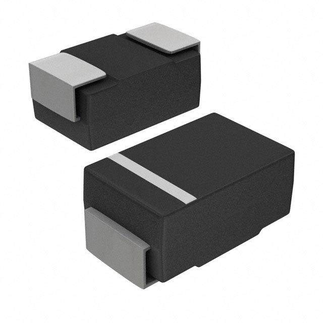
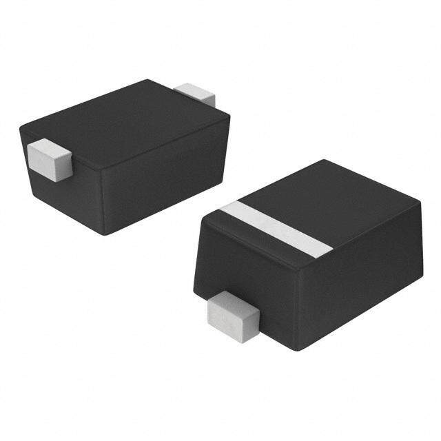
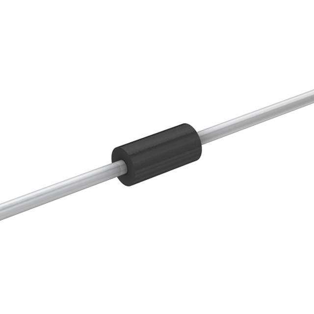
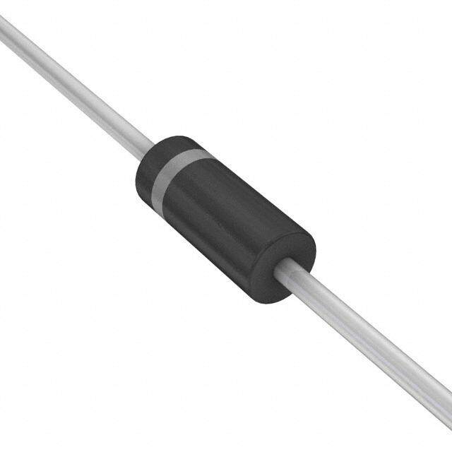
| 产品图片 |
|
| rohs | RoHS 合规性豁免不受无铅要求限制 / 符合限制有害物质指令(RoHS)规范要求 |
| 产品系列 | 二极管与整流器,TVS二极管,TVS 二极管 - 瞬态电压抑制器,Bourns SMCJ40CASMCJ |
| 数据手册 | |
| 产品型号 | SMCJ40CA |
| RoHS指令信息 | |
| 不同频率时的电容 | - |
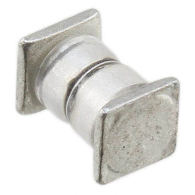
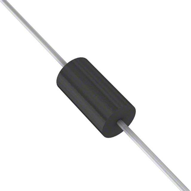
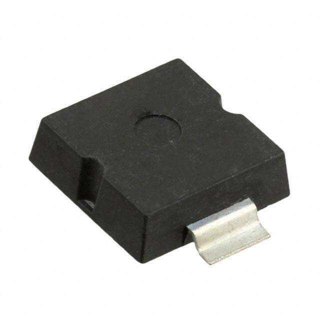
| 产品目录绘图 |
|
| 产品目录页面 | |
| 产品种类 | TVS 二极管 - 瞬态电压抑制器 |
| 供应商器件封装 | SMC (DO-214AB) |
| 其它名称 | SMCJ40CABCT |
| 击穿电压 | 44.4 V to 51.1 V |
| 功率-峰值脉冲 | 1500W (1.5kW) |
| 包装 | 剪切带 (CT) |
| 单向通道 | - |
| 双向通道 | 1 |
| 商标 | Bourns |
| 安装类型 | 表面贴装 |
| 安装风格 | SMD/SMT |
| 封装 | Reel |
| 封装/外壳 | DO-214AB,SMC |
| 封装/箱体 | DO-214AB |
| 尺寸 | 5.59 mm W x 7.11 mm L x 2.62 mm H |
| 峰值浪涌电流 | 200 A |
| 峰值脉冲功率耗散 | 1.5 kW |
| 工作温度 | -55°C ~ 150°C (TJ) |
| 工作电压 | 3.5 V |
| 工厂包装数量 | 3000 |
| 应用 | 通用 |
| 最大工作温度 | + 150 C |
| 最小工作温度 | - 55 C |
| 极性 | Bidirectional |
| 标准包装 | 1 |
| 特色产品 | http://www.digikey.com/product-highlights/cn/zh/bourns-smx-tvs-diodes/1448 |
| 电压-击穿(最小值) | 44.4V |
| 电压-反向关态(典型值) | 40V |
| 电压-箝位(最大值)@Ipp | - |
| 电流-峰值脉冲(10/1000µs) | - |
| 电源线路保护 | 无 |
| 端接类型 | SMD/SMT |
| 类型 | 齐纳 |
| 系列 | SMCJ |


PDF Datasheet 数据手册内容提取
SMCJ5.0 THRU SMCJ440CA Stand-off Voltage - 5.0 to 440 Volts Peak Pulse Power: 1500 Watts TRANSIENT VTAGE SUPPRESSOR Features For surface mounted applications in order to optimize board DO-214AB/SMC space Low profile package Built-in strain relief Glass passivated junction 0.126 (3.20) 0.245(6.22) 0.114 (2.90) 0.220(5.59) Low inductance Excellent clamping capability 1500W peak pulse power capability at 10/1000μs waveform, 0.280(7.11) 0.260(6.60) repetition rate (duty cycle): 0.01% Fast response time 0.012(0.305) 0.006(0.152) Typical IR less than 1μA above 10V High Temperature soldering: 260℃/10 seconds at terminals 0.103(2.62) 0.079(2.06) Plastic package has underwriters laboratory flammability 94V-0 0.060(1.52) 0.030(0.76) 0.008(0.203)MAX. 0.320(8.13) Mechanical Data 0.305(7.75) Case : JEDEC SMC molded plastic body Terminals : Solderable per MIL-STD-750,Method 2026 Dimensionsininchesand(millimeters) Polarity : Polarity symbol marking on body Mounting Position : Any Weight : 0.003 ounce, 0.095 grams Standard Packaging: 12mm tape (EIA STD RS-481) Applications I/Ointerface AC/DCpo w ersupply Lowfrequencysignaltransmissionline(RS232,RS485,etc.) MAXIMUM RATINGS AND CHARACTERISTICS Ratingsat25℃ ambienttemperatureunlessotherwisespecified. Peak pulse power dissipation at 10/1000μswaveform P Minimum 1500 W (Note1, Note2, Fig.1) PPM Peak pulse current of at 10/1000μs waveform (Note 1, Fig.3) I See Table A PPM Steady state power dissipation atTA=50℃(Fig.5) PM(AV) 6.5 W Peak forward surge current, 8.3ms single halfsine-wave I 200 A superimposed on rated load, (JEDEC Method) (Note3, Fig.6) FSM Operating junction and Storage Temperature Range. T ,T -65 to +150 ℃ J STG Typicalthermal resistance junction to lead R 15 ℃/W θJL Typicalthermal resistance junction to ambient R 75 ℃/W θJA Notes:1. Non-repetitive current pulse, per Fig.3 and derated above TA=25℃ per Fig.2. 2. Mounted on 5.0mm×5.0mm (0.03mm thick)copper pads to eachterminal. 3. 8.3mssinglehalfsine-wave,orequivalentsquarewave,dutycycle=4pulsesperminutesmaximum. DN:T20519A0 http://www.microdiode.com Rev:2020A0 Page :1
SMCJ5.0 THRU SMCJ440CA Stand-off Voltage - 5.0 to 440 Volts Peak Pulse Power: 1500 Watts Electrical Characteristics (TA=25℃℃) Maximum Device Reverse Breakdown Peak Reverse Test Clamping PartNumber Marking Stand-Off Voltage Pulse Leakage Current Voltage Code Voltage @IT @IPP Current @VRWM Unidirectional Bidirectional UNI BI VRWM(V) VBR(V) IT(mA) VC(V) IPP(A) IR(μA) SMCJ5.0A SMCJ5.0CA GDE BDE 5.0 6.40~7.00 10 9.2 163.0 800 SMCJ6.0A SMCJ6.0CA GDG BDG 6.0 6.67~7.37 10 10.3 145.7 800 SMCJ6.5A SMCJ6.5CA GDK BDK 6.5 7.22~7.98 10 11.2 134.0 500 SMCJ7.0A SMCJ7.0CA GDM BDM 7.0 7.78~8.60 10 12.0 125.0 200 SMCJ7.5A SMCJ7.5CA GDP BDP 7.5 8.33~9.21 1 12.9 116.3 100 SMCJ8.0A SMCJ8.0CA GDR BDR 8.0 8.89~9.83 1 13.6 110.3 50 SMCJ8.5A SMCJ8.5CA GDT BDT 8.5 9.44~10.40 1 14.4 104.2 20 SMCJ9.0A SMCJ9.0CA GDV BDV 9.0 10.00~11.10 1 15.4 97.4 10 SMCJ10A SMCJ10CA GDX BDX 10.0 11.10~12.30 1 17.0 88.3 5 SMCJ11A SMCJ11CA GDZ BDZ 11.0 12.20~13.50 1 18.2 82.5 1 SMCJ12A SMCJ12CA GEE BEE 12.0 13.30~14.70 1 19.9 75.4 1 SMCJ13A SMCJ13CA GEG BEG 13.0 14.40~15.90 1 21.5 69.8 1 SMCJ14A SMCJ14CA GEK BEK 14.0 15.60~17.20 1 23.2 64.7 1 SMCJ15A SMCJ15CA GEM BEM 15.0 16.70~18.50 1 24.4 61.5 1 SMCJ16A SMCJ16CA GEP BEP 16.0 17.80~19.70 1 26.0 57.7 1 SMCJ17A SMCJ17CA GER BER 17.0 18.90~20.90 1 27.6 54.4 1 SMCJ18A SMCJ18CA GET BET 18.0 20.00~22.10 1 29.2 51.4 1 SMCJ20A SMCJ20CA GEV BEV 20.0 22.20~24.50 1 32.4 46.3 1 SMCJ22A SMCJ22CA GEX BEX 22.0 24.40~26.90 1 35.5 42.3 1 SMCJ24A SMCJ24CA GEZ BEZ 24.0 26.70~29.50 1 38.9 38.6 1 SMCJ26A SMCJ26CA GFE BFE 26.0 28.90~31.90 1 42.1 35.7 1 SMCJ28A SMCJ28CA GFG BFG 28.0 31.10~34.40 1 45.4 33.1 1 SMCJ30A SMCJ30CA GFK BFK 30.0 33.30~36.80 1 48.4 31.0 1 SMCJ33A SMCJ33CA GFM BFM 33.0 36.70~40.60 1 53.3 28.2 1 SMCJ36A SMCJ36CA GFP BFP 36.0 40.00~44.20 1 58.1 25.9 1 SMCJ40A SMCJ40CA GFR BFR 40.0 44.40~49.10 1 64.5 23.3 1 SMCJ43A SMCJ43CA GFT BFT 43.0 47.80~52.80 1 69.4 21.7 1 SMCJ45A SMCJ45CA GFV BFV 45.0 50.00~55.30 1 72.7 20.6 1 SMCJ48A SMCJ48CA GFX BFX 48.0 53.30~58.90 1 77.4 19.4 1 SMCJ51A SMCJ51CA GFZ BFZ 51.0 56.70~62.70 1 82.4 18.2 1 SMCJ54A SMCJ54CA GGE BGE 54.0 60.00~66.30 1 87.1 17.3 1 SMCJ58A SMCJ58CA GGG BGG 58.0 64.40~71.20 1 93.6 16.1 1 SMCJ60A SMCJ60CA GGK BGK 60.0 66.70~73.70 1 96.8 15.5 1 SMCJ64A SMCJ64CA GGM BGM 64.0 71.10~78.60 1 103.0 14.6 1 SMCJ70A SMCJ70CA GGP BGP 70.0 77.80~86.00 1 113.0 13.3 1 SMCJ75A SMCJ75CA GGR BGR 75.0 83.30~92.10 1 121.0 12.4 1 SMCJ78A SMCJ78CA GGT BGT 78.0 86.70~95.80 1 126.0 11.9 1 SMCJ85A SMCJ85CA GGV BGV 85.0 94.40~104.00 1 137.0 11.0 1 SMCJ90A SMCJ90CA GGX BGX 90.0 100.00~111.00 1 146.0 10.3 1 SMCJ100A SMCJ100CA GGZ BGZ 100.0 111.00~123.00 1 162.0 9.3 1 SMCJ110A SMCJ110CA GHE BHE 110.0 122.00~135.00 1 177.0 8.5 1 SMCJ120A SMCJ120CA GHG BHG 120.0 133.00~147.00 1 193.0 7.8 1 http://www.microdiode.com Rev:2020A0 Page :2
SMCJ5.0 THRU SMCJ440CA Stand-off Voltage - 5.0 to 440 Volts Peak Pulse Power: 1500 Watts Electrical Characteristics (TA=25℃℃) Maximum Device Reverse Breakdown Peak Reverse Test Clamping PartNumber Marking Stand-Off Voltage Pulse Leakage Current Voltage Code Voltage @IT @IPP Current @VRWM Unidirectional Bidirectional UNI BI VRWM(V) VBR(V) IT(mA) VC(V) IPP(A) IR(μA) SMCJ130A SMCJ130CA GHK BHK 130.0 144.00~159.00 1 209.0 7.2 1 SMCJ150A SMCJ150CA GHM BHM 150.0 167.00~185.00 1 243.0 6.2 1 SMCJ160A SMCJ160CA GHP BHP 160.0 178.00~197.00 1 259.0 5.8 1 SMCJ170A SMCJ170CA GHR BHR 170.0 189.00~209.00 1 275.0 5.5 1 SMCJ180A SMCJ180CA GHT BHT 180.0 201.00~222.00 1 292.0 5.1 1 SMCJ190A SMCJ190CA GHU BHU 190.0 211.00~233.00 1 308.0 4.8 1 SMCJ200A SMCJ200CA GHV BHV 200.0 224.00~247.00 1 324.0 4.6 1 SMCJ210A SMCJ210CA GHW BHW 210.0 237.00~263.00 1 340.0 4.4 1 SMCJ220A SMCJ220CA GHX BHX 220.0 246.00~272.00 1 356.0 4.2 1 SMCJ250A SMCJ250CA GHZ BHZ 250.0 279.00~309.00 1 405.0 3.7 1 SMCJ300A SMCJ300CA GJE BJE 300.0 335.00~371.00 1 486.0 3.1 1 SMCJ350A SMCJ350CA GJG BJG 350.0 391.00~432.00 1 567.0 2.6 1 SMCJ400A SMCJ400CA GJK BJK 400.0 447.00~494.00 1 648.0 2.3 1 SMCJ440A SMCJ440CA GJM BJM 440.0 492.00~543.00 1 713.0 2.1 1 Notes:ForbidirectionaltypehavingV of10Vandless,theI limitisdouble. RWM R Figure1.PeakPulsePowerRatingCurve Figure2.PulseDeratingCurve 100 W) er (k 80 w o e P 60 s ul P ak 40 e P - PPPM 20 0 0 25 50 75 100 125 150 175 TA-Ambient Temperature(℃) Figure3.PulseWaveform Figure4.TypicalJunctionCapacitance M RS %I nt, e urr C e s ul P k a e P - M IPP http://www.microdiode.com Rev:2020A0 Page :3
SMCJ5.0 THRU SMCJ440CA Stand-off Voltage - 5.0 to 440 Volts Peak Pulse Power: 1500 Watts Figure5.SteadyStatePowerDissipationDerating Figure6.MaximumNon-RepetitiveForward Curve SurgeCurrentUni-DirectionalOnly W) ( n o ati p si s Di er w o P e at St y d a e St ,M(AV) P ReflowSoldering RecommendedConditions ProfileFeature Pb-FreeAssembly Averageramp-uprate(TLtoTP) 3℃/secondmax. Preheat -TemperatureMin(TSmin) 150℃ -TemperatureMax(TSmax) 200℃ -Time(mintomax)(tS) 60-180seconds TSmaxtoTL -Ramp-upRate 3℃/secondmax. Timemaintainedabove: -Temperature(TL) 217℃ -Time(tL) 60-150seconds PeakTemperature(TP) 260℃ Timewithin5℃ofactualPeakTemperature(tP) 20-40seconds Ramp-downRate 6℃/secondmax. Time25℃toPeakTemperature 8minutesmax. The curve above is for reference only. http://www.microdiode.com Rev:2020A0 Page :4
SMCJ5.0 THRU SMCJ440CA Stand-off Voltage - 5.0 to 440 Volts Peak Pulse Power: 1500 Watts Packing information unit:mm P0 P1 d Item Symbol Tolerance SMC E F Carrier width A 0.1 6.15 B W Carrier length B 0.1 8.41 Carrier depth C 0.1 2.42 Sprocket hole d 0.05 1.50 13" Reel outside diameter D 2.0 330.00 A P 13" Reel inner diameter D1 min 50.00 Feed hole diameter D2 0.5 13.00 Sprocket hole position E 0.1 1.75 Punch hole position F 0.1 7.50 T D2 D1 Punch hole pitch P 0.1 8.00 Sprocket hole pitch P0 0.1 4.00 C Embossment center P1 0.1 2.00 Overall tape thickness T 0.1 0.25 D W1 Tape width W 0.3 16.00 Reel width W1 1.0 16.50 Note:Devices are packed in accor dance with EIA standar RS-481-A and specifications listed above. Reel packing COMPONENT INNER REEL CARTON APPROX. PACKAGE REELSIZE REEL SPACING BOX BOX DIA, SIZE CARTON GROSS WEIGHT (pcs) (mm) (pcs) (mm) (mm) (mm) (pcs) (kg) SMC 13" 3,000 4.0 6000 190*190*41 330 365*365*340 42000 14.0 Suggested Pad Layout Symbol Unit (mm) Unit (inch) A 4.3 0.170 B 4.1 0.160 C 7.9 0.311 D 3.8 0.150 E 12 0.472 Important Notice and Disclaimer Microdiode Electronics (Jiangsu) reserves the right to make changes to this document and its products and specifications at any time without notice. Customers should obtain and confirm the latest product information and specifications before final design,purchase or use. Microdiode Electronics (Jiangsu) makes no warranty, representation or guarantee regarding the suitability of its products for any particular purpose, not does Microdiode Electronics (Jiangsu) assume any liability for application assistance or customer product design. Microdiode Electronics (Jiangsu) does not warrant or accept any liability with products which are purchased or used for any unintended or unauthorized application. No license is granted by implication or otherwise under any intellectual property rights of Microdiode Electronics (Jiangsu). Microdiode Electronics (Jiangsu) products are not authorized for use as critical components in life support devices or systems without express written approval of Microdiode Electronics (Jiangsu). http://www.microdiode.com Rev:2020A0 Page :5