 Datasheet下载
- 型号: SM712.TCT
- 制造商: SEMTECH
- 库位|库存: xxxx|xxxx
- 要求:
| 数量阶梯 | 香港交货 | 国内含税 |
| +xxxx | $xxxx | ¥xxxx |
查看当月历史价格
查看今年历史价格
SM712.TCT产品简介:
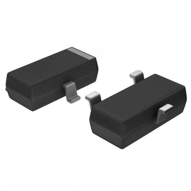
ICGOO电子元器件商城为您提供SM712.TCT由SEMTECH设计生产,在icgoo商城现货销售,并且可以通过原厂、代理商等渠道进行代购。 SM712.TCT价格参考¥3.16-¥3.95。SEMTECHSM712.TCT封装/规格:TVS - 二极管, 26V, 12V Clamp 17A (8/20µs) Ipp Tvs Diode Surface Mount SOT-23-3。您可以下载SM712.TCT参考资料、Datasheet数据手册功能说明书,资料中有SM712.TCT 详细功能的应用电路图电压和使用方法及教程。
| 参数 | 数值 |
| 产品目录 | |
| 描述 | TVS DIODE 12VWM/7VWM SOT23 |
| 产品分类 | |
| 品牌 | Semtech |
| 数据手册 | |
| 产品图片 |
|
| 产品型号 | SM712.TCT |
| rohs | 无铅 / 符合限制有害物质指令(RoHS)规范要求 |
| 产品系列 | - |
| 不同频率时的电容 | 75pF @ 1MHz |
| 产品目录页面 | |
| 供应商器件封装 | SOT-23-3 |
| 其它名称 | SM712DKR |
| 功率-峰值脉冲 | 400W |
| 包装 | Digi-Reel® |
| 单向通道 | - |
| 双向通道 | 2 |
| 安装类型 | 表面贴装 |
| 封装/外壳 | TO-236-3,SC-59,SOT-23-3 |
| 工作温度 | -55°C ~ 125°C (TJ) |
| 应用 | 通用 |
| 标准包装 | 1 |
| 电压-击穿(最小值) | 13.3V, 7.5V |
| 电压-反向关态(典型值) | 12V (最小值), 7V (最小值) |
| 电压-箝位(最大值)@Ipp | 26V, 12V |
| 电流-峰值脉冲(10/1000µs) | 17A (8/20µs) |
| 电源线路保护 | 无 |
| 类型 | 齐纳 |


- 商务部:美国ITC正式对集成电路等产品启动337调查
- 曝三星4nm工艺存在良率问题 高通将骁龙8 Gen1或转产台积电
- 太阳诱电将投资9.5亿元在常州建新厂生产MLCC 预计2023年完工
- 英特尔发布欧洲新工厂建设计划 深化IDM 2.0 战略
- 台积电先进制程称霸业界 有大客户加持明年业绩稳了
- 达到5530亿美元!SIA预计今年全球半导体销售额将创下新高
- 英特尔拟将自动驾驶子公司Mobileye上市 估值或超500亿美元
- 三星加码芯片和SET,合并消费电子和移动部门,撤换高东真等 CEO
- 三星电子宣布重大人事变动 还合并消费电子和移动部门
- 海关总署:前11个月进口集成电路产品价值2.52万亿元 增长14.8%


PDF Datasheet 数据手册内容提取
SM712 Asymmerical TVS Diode for Extended Common-Mode RS-485 PROTECTION PRODUCTS Description Features The SM712 transient voltage suppressor (TVS) diode • Transient Protection to s IEC 61000-4-2 (ESD): ±30kV (Air), ±30kV (Contact) is designed for asymmetrical (12V to -7V) protection s IEC 61000-4-4 (EFT): 40A (5/50ns) in multi-point data transmission standard RS-485 s IEC 61000-4-5 (Lightning): 21A for 12V TVS & 38A applications. The SM712 may be used to protect devices for 7V TVS (tp = 8/20µs) from transient voltages resulting from electrostatic • Protects two +12V to -7V lines discharge (ESD), eletrical fast transients (EFT), and • Peak pulse power (tp = 8/20μs): 500-700W lightning. • Low capacitance • Low clamping voltage • Solid-State Silicon-Avalanche Technology The SM712 features more than 500 Watts (tp = 8/20 μs) of power handling capability to accommodate the Mechanical Characteristics higher transient voltage levels which may be expected • JEDEC SOT23 Package in extended commom mode applications. This provides • Molding Compound Flammability Rating: UL 94V-0 higher equipment reliability and eliminates the “guess • Pb-Free, Halogen Free, RoHS/WEEE compliant work“ required when using Zener diodes that are not • Marking: 712 rated to handle such transient conditions. • Packaging: Tape and Reel Applications The SM712 replaces four discrete components by integrating two 12V and two 7V TVS diodes in a single • RS-485 tranceivers with extended common mode package. The integrated design aids in reducing voltage range over-shoot associated with trace inductance. The low • Security systems clamping voltage of SM712 minimizes the stress on the • Automatic Teller Machines • HFC systems protected transceiver. • Networks Circuit Diagram Schematic and Pin Confi guration I/O 1 I/O 2 3 1 2 12V 12V 7V 7V SM712 1 2 GND 3 SOT23 (Top View) SM712 www.semtech.com Page 1 Final Datasheet Rev 6.0 Semtech 10/17/2017
Absolute Maximum Ratings Rating Symbol Value Units Peak Pulse Power (tp = 8/20µs) P 550- 700 W PK Peak Pulse Current (tp = 8/20µs), Pin 1 or 2 to Pin 3 21 I A Peak Pulse Current (tp = 8/20µs), Pin 3 to Pin 1 or 2 PP 38 ESD per IEC 61000-4-2 (Contact)(1) 30 V kV ESD per IEC 61000-4-2 (Air)(1) ESD 30 Lead Soldering Temperature T 260 (10 sec.) OC L Operating Temperature T -55 to +125 OC J Storage Temperature T -55 to +150 OC STG Electrical Characteristics (T=25OC unless otherwise specifi ed) Parameter Symbol Conditions Min. Typ. Max. Units Pin 1 or Pin 2 to 3 12 Reverse Stand-Off Voltage V V RWM Pin 3 to Pin 1 or 2 7 I = 1mA, Pin 1 or 2 to Pin 3 13.3 V Reverse Breakdown Voltage V t BR I = 1mA, Pin 3 and Pin 1 or 2 7.5 t V = 12 V, Pin 1 or Pin 2 to 3 1 Reverse Leakage Current I R μA R V = 7 V, Pin 3 to Pin 1 or 2 20 R I = 5A, Pin 1 or 2 to Pin 3, tp = 8/20µs 20 Clamping Voltage V PP V C I = 5A, Pin 3 to Pin 1 or 2, tp = 8/20µs 10 PP I = 21A, Pin 1 or 2 to Pin 3, tp = 8/20µs 26 Clamping Voltage V PP V C I = 38A, Pin 3 to Pin 1 or 2, tp = 8/20µs 19 PP Pin 1 or 2 to Pin 3 75 V = 0V R Pin 3 to Pin 1 or 2 75 Junction Capacitance C pF J V =12V Pin 1 or 2 to Pin 3 57 R V =7V Pin 3 to Pin 1 or 2 35 R Notes: (1): ESD Gun return path to Ground Reference Plane (GRP) (2): Transmission Line Pulse Test (TLP) Settings: tp = 100ns, tr = 0.2ns, I and V averaging window: t = 70ns to t = 90ns. TLP TLP 1 2 (3): Dynamic resistance calculated from I = 4A to I = 16A. TLP TLP SM712 www.semtech.com Page 2 Final Datasheet Rev 6.0 Semtech 10/17/2017
Typical Characteristics Non-Repetitive Peak Pulse Power vs. Pulse Time Power Derating Curve 120 10 W) 100 k (P wer - PP 1 Pin 3 to Pin 1 or 2 er or I PP 80 Po ow 60 se d P ak Pul0.1 Pin 1 or 2 to Pin 3 of Rate 40 Pe % 20 T = 25OC 0.01 A 0 DR040514-25-125-150 0.1 1 10 100 1000 0 25 50 75 100 125 150 Pulse Duration - tp (µs) Ambient Temperature - T (OC) A Clamping Voltage vs. Peak Pulse Current (tp = 8/20µs) Capacitance vs. Reverse Voltage 30 80 70 25 V) Pin 1 or 2 to Pin 3 60 V (C 20 Pin 3 to Pin 1 or 2 ge - pF) 50 Clamping Volta 1105 Pin 3 to Pin 1 or 2 apacitance - C (J 234000 Pin 1 or 2 to Pin 3 C 5 10 T = 25OC. A f = 1 MHz. 0 SM712 8x20us 7V 0 SM712_AR_CAPvV 0 5 10 15 20 25 30 35 40 0 2 4 6 8 10 12 14 Peak Pulse Current - I (A) Reverse Voltage - V (V) PP R TLP IV Curve (Pin 1 or 2 to Pin 3) TLP IV Curve (Pin 3 to Pin 1 or 2) 35 5 30 TttPMA =E=A S12 0=50 O7nC0s -,9 t0Rn =s 0.2ns 0 TtttPRMA =E==A S102 0=.520 O7nnC0ss - 90ns 25 -5 nt (A) 20 nt (A) -10 e15 e urr urr-15 C C P 10 P L L T T -20 5 -25 0 SM712_TLP_POS SM712_TLP_NEG -5 -30 0 5 10 15 20 25 -14 -12 -10 -8 -6 -4 -2 0 TLP Voltage (V) TLP Voltage (V) SM712 www.semtech.com Page 3 Final Datasheet Rev 6.0 Semtech 10/17/2017
Typical Characteristics ESD Clamping Voltage (+8kV Contact per IEC 61000-4-2) ESD Clamping Voltage (-8kV Contact per IEC 61000-4-2) 180 0 160 TWA a=v 2ef5oOrCm. IEC61000-4-2 +8kV. -20 Measured with and corrected for 50Ω, 40dB Attenuator. g Voltage - V (V) C 11148020000 5ES0DΩ GScuonp Ree Itnuprunt c Iomnpneedcatendce t,o ≥ G2rGoHuzn Bd WRe. ference Plane. Voltage - V (V) C -1---08640000 pin 60 ng -120 m pi Cla 40 Clam -140 TWA a=v 2ef5oOrCm. IEC61000-4-2 -8kV. Measured with and corrected for 50Ω, 40dB Attenuator. 20 -160 50Ω Scope Input Impedance, ≥2GHz BW. ESD Gun Return connected to ESD Ground Plane. SM712_P8_ESD 0 -180 SM712_IEC_N8_ESD -10 10 30 50 70 90 -10 10 30 50 70 90 Time (ns) Time (ns) SM712 www.semtech.com Page 4 Final Datasheet Rev 6.0 Semtech 10/17/2017
Application Information Device Connection for Protection of Two RS-485 Data RS-485 Common Mode Voltages Lines EIA RS-485 specifi es a ±7V ground diff erence between VCC1 VCC2 devices on the bus. This permits the bus voltage to 5V 5V range from +12V (5V + 7V) to -7V (0-7V). 4000 ft Twisted Pair A B The SM712 is designed to protect two RS-485 data lines INPUT 100 100 OUTPUT in extended common mode applications. The SM712 B A may be used to protect devices from transient voltages GND - + resulting from ESD, EFT, and lightning. The device is 12V to -7V designed with asymmetrical operating voltages for Common mode voltage optimum protection. The TVS diodes at pins 1 and 2 have a working voltage of 12 volts. These pins are connected to the diff erential data line pairs. The TVS RS-485 Protection Circuit diodes at pin 3 have a working voltage of 7 volts. Pin 3 is connected to ground. The internal TVS diodes of the VCC SM712 will protect the transceiver input from positive 5V SS transient votlage spikes greater than 12V and negative RT SS spikes greater than 7V. SM05 A series current limiting resistor may be added in applications requiring enhanced surge immunity. D Circuit Board Layout Recommendations 12V 12V Good circuit board layout is critical for the suppression R of fast rise time transients such as ESD. The following 7V 7V guidelines are recommended: SM712 • Place the SM712 near the input terminals or connectors to restrict electromagnetic coupling. • Minimize the path length between the SM712 and the protected line. This minimizes voltage overshoot due to parastic inductance of board traces. • Use ground planes whenever possible. • Long, single trace ground conductors should be avoided. The ground pin (Pin 3) should be connected directly to a ground plane on the circuit board for best results. • Minimize all conductive loops including power and ground loops. • Never run critical signals near board edges. SM712 www.semtech.com Page 5 Final Datasheet Rev 6.0 Semtech 10/17/2017
Outline Drawing - SOT-23 e1 DIMENSIONS 3 B DIM MILLIMETERS MINNOMMAX A 0.89 - 1.20 A1 0.01 - 0.10 A2 0.88 - 1.10 E1 E bc 00..3008 -- 00..5118 D 2.80 2.90 3.04 E1 1.20 1.30 1.40 E 2.10 - 2.64 e 1.90BSC e1 0.95BSC 1 2 L 0.40 0.50 0.60 L1 (0.55) bxN N 3 bbb C A B 0 0° - 8° e aaa 0.10 bbb 0.20 D A aaaC A2 A SEATING PLANE C A1 H GAUGEPLANE 0 c SEATING PLANE C 0.25 L SIDEVIEW L1 SEEDETAILA DETAILA NOTES: 1. CONTROLLINGDIMENSIONSAREINMILLIMETERS(ANGLESINDEGREES). 2. DATUMS -A- AND -B- TOBEDETERMINEDATDATUMPLANE-H- 3. DIMENSIONS"E1"AND"D"DONOTINCLUDEMOLDFLASH,PROTRUSIONS ORGATEBURRS. Land Pattern - SOT-23 X DIMENSIONS DIMMILLIMETERS C (2.20) Z (C) G G 0.80 E1 0.95 E 1.90 X 1.00 Y 1.40 Z 3.60 Y E1 E NOTES: 1. CONTROLLINGDIMENSIONSAREINMILLIMETERS(ANGLESINDEGREES). 2. THISLANDPATTERNISFORREFERENCEPURPOSESONLY CONSULTYOURMANUFACTURINGGROUPTOENSUREYOUR COMPANY'SMANUFACTURINGGUIDELINESAREMET. 3. REFERENCEIPC-SM-782A. SM712 www.semtech.com Page 6 Final Datasheet Rev 6.0 Semtech 10/17/2017
Marking Code 3 712 1 2 Tape and Reel Specifi cation 712 712 712 Pin 1 Location User Direction of feed Ordering Information Part Number Qty per Reel Reel Size Carrier Tape Pitch SM712.TCT 3,000 7 Inch Plastic 4mm MicroClamp and uClamp are registered trademarks of Semtech Corporation. SM712 www.semtech.com Page 7 Final Datasheet Rev 6.0 Semtech 10/17/2017
IMPORTANT NOTICE Information relating to this product and the application or design described herein is believed to be reliable, however such information is provided as a guide only and Semtech assumes no liability for any errors in this document, or for the application or design described herein. Semtech reserves the right to make changes to the product or this document at any time without notice. Buyers should obtain the latest relevant information before placing orders and should verify that such information is current and complete. Semtech warrants performance of its products to the specifi cations applicable at the time of sale, and all sales are made in accordance with Semtech’s standard terms and conditions of sale. SEMTECH PRODUCTS ARE NOT DESIGNED, INTENDED, AUTHORIZED OR WARRANTED TO BE SUITABLE FOR USE IN LIFE-SUPPORT APPLICATIONS, DEVICES OR SYSTEMS, OR IN NUCLEAR APPLICATIONS IN WHICH THE FAILURE COULD BE REASONABLY EXPECTED TO RESULT IN PERSONAL INJURY, LOSS OF LIFE OR SEVERE PROPERTY OR ENVIRONMENTAL DAMAGE. INCLUSION OF SEMTECH PRODUCTS IN SUCH APPLICATIONS IS UNDERSTOOD TO BE UNDERTAKEN SOLELY AT THE CUSTOMER’S OWN RISK. Should a customer purchase or use Semtech products for any such unauthorized application, the customer shall indemnify and hold Semtech and its offi cers, employees, subsidiaries, affi liates, and distributors harmless against all claims, costs damages and attorney fees which could arise. The Semtech name and logo are registered trademarks of the Semtech Corporation. All other trademarks and trade names mentioned may be marks and names of Semtech or their respective companies. Semtech reserves the right to make changes to, or discontinue any products described in this document without further notice. Semtech makes no warranty, representation or guarantee, express or implied, regarding the suitability of its products for any particular purpose. All rights reserved. © Semtech 2015 Contact Information Semtech Corporation 200 Flynn Road, Camarillo, CA 93012 Phone: (805) 498-2111, Fax: (805) 498-3804 www.semtech.com SM712 Page 8 Final Datasheet Rev 6.0 Semtech 10/17/2017