 Datasheet下载
- 型号: SF1186B-2
- 制造商: Murata
- 库位|库存: xxxx|xxxx
- 要求:
| 数量阶梯 | 香港交货 | 国内含税 |
| +xxxx | $xxxx | ¥xxxx |
查看当月历史价格
查看今年历史价格
SF1186B-2产品简介:
ICGOO电子元器件商城为您提供SF1186B-2由Murata设计生产,在icgoo商城现货销售,并且可以通过原厂、代理商等渠道进行代购。 SF1186B-2价格参考¥5.00-¥10.87。MurataSF1186B-2封装/规格:SAW 滤波器, 。您可以下载SF1186B-2参考资料、Datasheet数据手册功能说明书,资料中有SF1186B-2 详细功能的应用电路图电压和使用方法及教程。
Murata Electronics North America 生产的 SF1186B-2 SAW(声表面波)滤波器是一种高性能的射频滤波器,广泛应用于各种通信设备中。SAW 滤波器利用压电材料的声表面波特性来实现信号的选择和过滤,具有体积小、性能稳定、成本低等优点。

 应用场景:

1. 无线通信设备:
   - 移动电话:SF1186B-2 可用于手机中的射频前端模块,帮助过滤不必要的频率成分,确保接收和发送信号的纯净度。它能够有效减少干扰,提高通话质量和数据传输速率。
   - 基站设备:在基站中,该滤波器可以用于信号处理部分,确保基站与终端设备之间的通信更加稳定可靠。

2. 物联网 (IoT) 设备:
   - 智能家居:在智能门锁、智能摄像头等设备中,SAW 滤波器可以确保无线信号的稳定传输,避免外界干扰。
   - 工业物联网:在工厂自动化、远程监控等应用中,该滤波器可以提高无线通信的可靠性和抗干扰能力,确保数据传输的准确性。

3. 汽车电子:
   - 车载通信系统:如车载Wi-Fi、蓝牙、GPS等,SAW 滤波器可以帮助这些系统在复杂的电磁环境中保持良好的通信质量。
   - V2X 通信:车辆到一切(Vehicle-to-Everything)通信系统中,SAW 滤波器可以确保车辆与基础设施或其他车辆之间的高效通信。

4. 军事和航空航天:
   - 雷达系统:SAW 滤波器可以用于雷达系统的信号处理部分,确保雷达信号的高精度和可靠性。
   - 卫星通信:在卫星通信设备中,该滤波器可以提高信号的传输效率,减少噪声和干扰。

5. 消费电子:
   - 无线耳机:在蓝牙耳机、智能手表等可穿戴设备中,SAW 滤波器可以确保无线连接的稳定性,提供更好的用户体验。
   - 遥控器:在电视、空调等家电的遥控器中,SAW 滤波器可以提高信号的传输距离和抗干扰能力。

总之,Murata SF1186B-2 SAW 滤波器凭借其优异的性能和广泛的适用性,在多个领域中发挥着重要作用,特别是在需要高精度、低噪声和高可靠性的无线通信应用中表现尤为突出。
| 参数 | 数值 |
| 产品目录 | |
| 描述 | SAW RF / IF FILTER 1575.42 MHZ信号调节 1575.42 MHz, GPS RF SAW Filter |
| 产品分类 | |
| 品牌 | Murata Electronics |
| 产品手册 | |
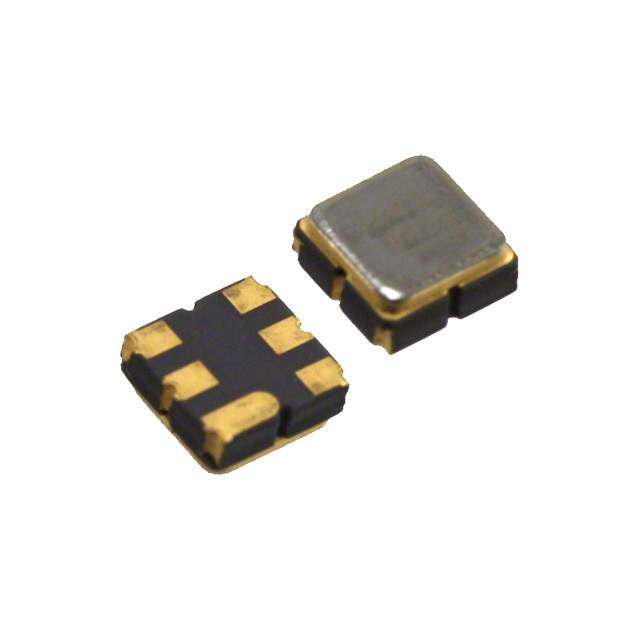
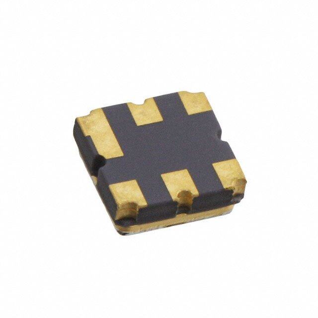
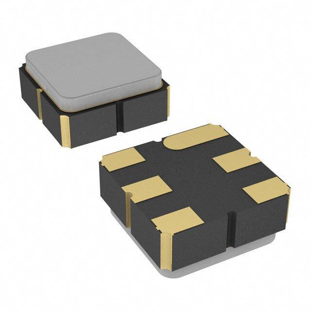
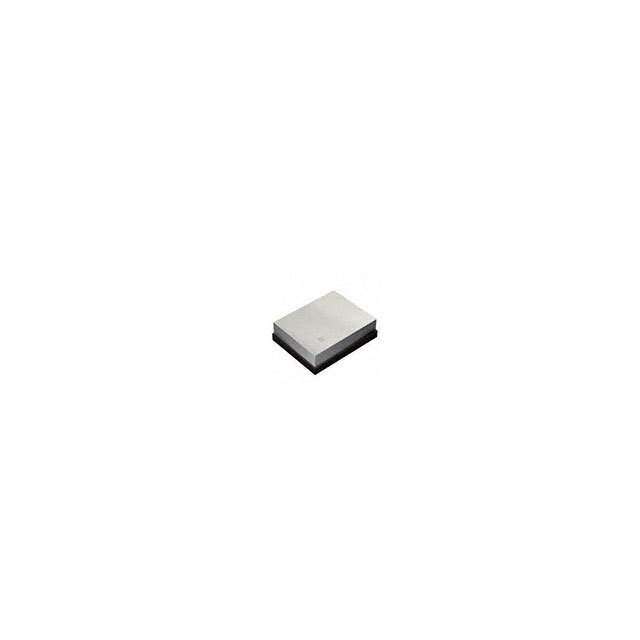
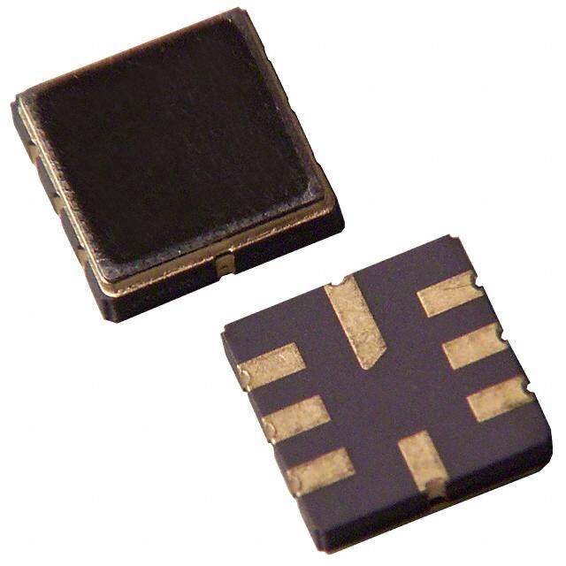
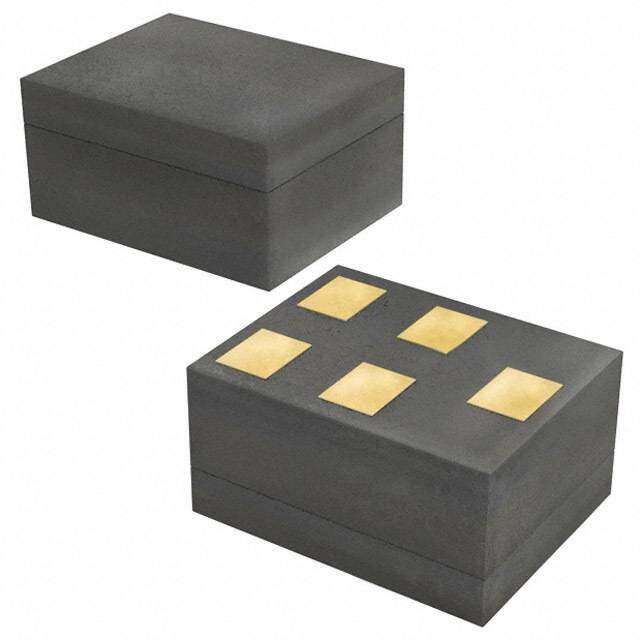
| 产品图片 |
|
| rohs | 符合RoHS无铅 / 符合限制有害物质指令(RoHS)规范要求 |
| 产品系列 | Murata Electronics SF1186B-2- |
| 数据手册 | |
| 产品型号 | SF1186B-2 |
| 产品 | SAW Filters |
| 产品目录页面 | |
| 产品种类 | 信号调节 |
| 介入损耗 | 2.68 dB |
| 其它名称 | 583-1085-6 |
| 包装 | Digi-Reel® |
| 商标 | Murata Electronics |
| 大小/尺寸 | 0.118" 长 x 0.118" 宽(3.00mm x 3.00mm) |
| 安装类型 | 表面贴装 |
| 封装 | Reel |
| 封装/外壳 | 6-SMD,无引线 |
| 封装/箱体 | SM-3030-6 |
| 工作温度范围 | - 40 C to + 85 C |
| 工厂包装数量 | 500 |
| 带宽 | 15 MHz |
| 应用 | GPS |
| 插入损耗 | 2.68dB |
| 标准包装 | 1 |
| 滤波器类型 | 带通 |
| 电压额定值 | 4 VDC |
| 端接类型 | SMD/SMT |
| 类型 | SAW Filter |
| 频率 | 1575.42 MHZ |
| 高度(最大值) | 0.054"(1.38mm) |


- 商务部:美国ITC正式对集成电路等产品启动337调查
- 曝三星4nm工艺存在良率问题 高通将骁龙8 Gen1或转产台积电
- 太阳诱电将投资9.5亿元在常州建新厂生产MLCC 预计2023年完工
- 英特尔发布欧洲新工厂建设计划 深化IDM 2.0 战略
- 台积电先进制程称霸业界 有大客户加持明年业绩稳了
- 达到5530亿美元!SIA预计今年全球半导体销售额将创下新高
- 英特尔拟将自动驾驶子公司Mobileye上市 估值或超500亿美元
- 三星加码芯片和SET,合并消费电子和移动部门,撤换高东真等 CEO
- 三星电子宣布重大人事变动 还合并消费电子和移动部门
- 海关总署:前11个月进口集成电路产品价值2.52万亿元 增长14.8%
PDF Datasheet 数据手册内容提取
SF1186B-2 • Designed for Front-end GPS Applications • Low Insertion Loss Pb 1575.42 MHz • 3.0 x 3.0 x 1.3 mm Surface-mount Case • No Matching Network Required SAW Filter • Complies with Directive 2002/95/EC (RoHS) • Qualified per AEC-Q200 requirements Maximum Ratings Rating Symbol Value Units Maximum Input Signal Level +10 dBm DC Voltage on any Non-ground Terminal WVdc 4 Volts Operable Temperature Range -45 to +125 °C Storage Temperature Range TSTG -40 to +105 °C Lead Soldering Temperature for 10 Seconds TWAVE 260 °C Peak Reflow Solder Temp for 40 Seconds TReflow 235 °C SM3030-6 Suitable for Lead-free Soldering - Max Soldering Temperature 260°C for 30 s Electrical Characteristics Characteristic Sym Notes Min Typ Max Units Center Frequency f 1 1575.42 MHz O 1 dB Bandwidth BW 1 2.046 15.3 MHz 1 Passband Amplitude Ripple, f ±2.0 MHz 0.1 1.0 dB O P-P Passband Group Delay 27 ns Passband Group Delay Ripple, f ±2.0 MHz 1 ns O P-P Passband VSWR, f ±2.0 MHz 1.4 2.0 O Insertion Loss 1 2.68 3.5 dB Attenuation Referenced to 0 dB: 850 MHz 1 45 51.2 1500 MHz 1 40 52.7 1535.42 MHz 1 20 38.9 dB 1615.42 MHz 1 20 58.8 1640 MHz 1 45 59.1 1700 MHz 1 50 56.7 Temperature Coefficient -30 ppm/°C Operating Temperature T 1 -40 +85 °C A Single-ended Input /Output Impedance Match No matching network required for operation at 50 ohms Case Style SM3030-6 3 x 3 mm Nominal Footprint Lid Symbolization y=year, ww=week, s=shift 468 YWWS Standard Reel Quantity Reel Size 7 Inch 500 Pieces/Reel 6 Reel Size 13 Inch 3000 Pieces/Reel Electrical Connections Pin # Description Pin # Description 1 Ground 4 Ground 2 Input 5 Output 3 Ground 6 Ground CAUTION: Electrostatic Sensitive Device. Observe precautions for handling. NOTES: 1. Unless noted otherwise, all specifications apply over the operating temperature range with filter soldered to the specified demonstration board without imped- ance matching and measured with 50 network analyzer. 2. The design, manufacturing process, and specifications of this filter are subject to change. 3. Either Port 1 or Port 2 may be used for either input or output in the design. However, impedances and impedance matching may vary between Port 1 and Port 2, so that the filter must always be installed in one direction per the circuit design. 4. US and international patents may apply. 5. Murata, stylized Murata logo, and Murata N.A., Inc. are registered trademarks of Murata Manufacturing Co., Ltd. 6. Tape and Reel Standard Per ANSI/EIA 481. Copyright © Murata Manufacturing Co., Ltd. All rights reserved. April 2014 www.murata.com SF1186B-2 (R) 5/2/17 Page 1 of 7
Transfer function : (1) S21 response (span : 300 MHz) (2) S21 response (span : 3 GHz) Copyright © Murata Manufacturing Co., Ltd. All rights reserved. April 2014 www.murata.com SF1186B-2 (R) 5/2/17 Page 2 of 7
Reflection Functions: S11 S22 Copyright © Murata Manufacturing Co., Ltd. All rights reserved. April 2014 www.murata.com SF1186B-2 (R) 5/2/17 Page 3 of 7
Reflection Functions: Copyright © Murata Manufacturing Co., Ltd. All rights reserved. April 2014 www.murata.com SF1186B-2 (R) 5/2/17 Page 4 of 7
Group Delay: 28 Oct 2010 10:49:43 CH1 S21 DEL 10 ns/ REF 0 s 3: 422 .72 ps -4 .000 000 MHz SF1186B-2 GDD S mo CH1 MRaErFke=r2s mean : 27.016 ns C s.dev : 240 .27 ps p-p : 869 .03 ps 3 1 2 Full CENTER 1 575 .830 000 MHz SPAN 40.000 000 MHz Copyright © Murata Manufacturing Co., Ltd. All rights reserved. April 2014 www.murata.com SF1186B-2 (R) 5/2/17 Page 5 of 7
SM3030-6 Case 6-Terminal Ceramic Surface-Mount Case 3.0 X 3.0 mm Nominal Footprint Case and PCB Footprint Dimensions mm Inches Dimension Min Nom Max Min Nom Max A 2.87 3.00 3.13 0.113 0.118 0.123 B 2.87 3.00 3.13 0.113 0.118 0.123 C 1.12 1.25 1.38 0.044 0.049 0.054 D 0.77 0.90 1.03 0.030 0.035 0.040 E 2.67 2.80 2.93 0.105 0.110 0.115 F 1.47 1.60 1.73 0.058 0.063 0.068 G 0.72 0.85 0.98 0.028 0.033 0.038 H 1.37 1.50 1.63 0.054 0.059 0.064 I 0.47 0.60 0.73 0.019 0.024 0.029 (cid:2) J 1.17 1.30 1.43 0.046 0.051 0.056 (cid:6) K 3.20 0.126 L 1.70 0.067 (cid:5) M 1.05 0.041 N 0.81 0.032 O 0.38 0.015 (cid:2) (cid:5) Case Materials (cid:3) Materials (cid:5) Solder Pad 0.3 to 1.0 µm Gold over 1.27 to 8.89 µm Nickel Plating (cid:4) (cid:4) Lid Plating 2.0 to 3.0 µm Nickel PCB Footprint Top View Body Al2O3 Ceramic Pb Free TOP VIEW BOTTOM VIEW B C G H 1 6 6 1 Y W 4 A 2 6 5 E F 5 2 I W 8 S 3 4 4 3 D J Copyright © Murata Manufacturing Co., Ltd. All rights reserved. April 2014 www.murata.com SF1186B-2 (R) 5/2/17 Page 6 of 7
Tape and Reel Specifications “B” Quantity Per Reel .F F. Inches millimeters E E R R 0 " 7 178 500 0 B 1 " 13 330 3000 See Detail "A" 12.0 0 3. 1 2.0 20.2 COMPONENT ORIENTATION 0.3 2.0 4.0 PIN #1 1.5 A 75 1. RO.3 (MAX.) 5 5. 0 2. 3.35 1 B B A 3.35 8.0 R0.5 (TYP.) 1.4 1.5 SECTION A-A USER DIRECTION OF FEED SECTION B-B Copyright © Murata Manufacturing Co., Ltd. All rights reserved. April 2014 www.murata.com SF1186B-2 (R) 5/2/17 Page 7 of 7