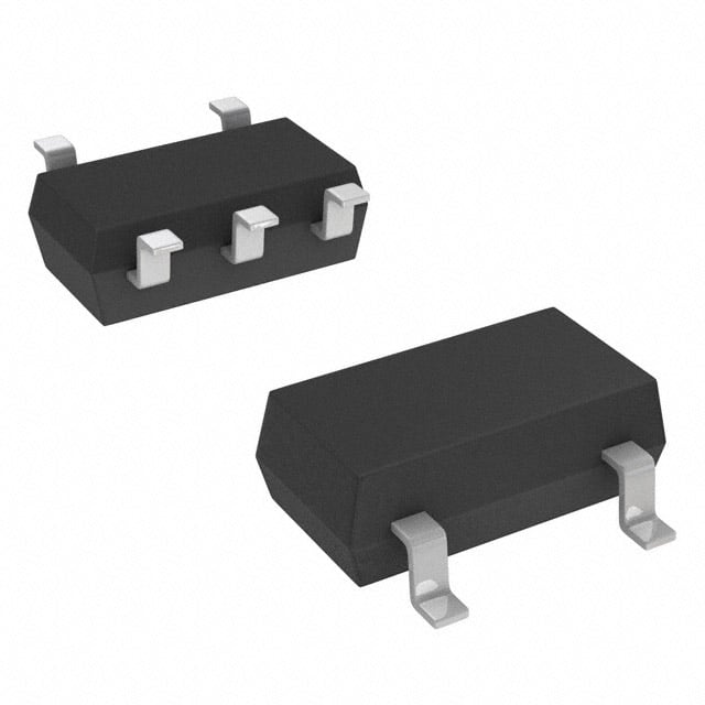
- 型号: SDP0120T023G5RP
- 制造商: Littelfuse
- 库位|库存: xxxx|xxxx
- 要求:
| 数量阶梯 | 香港交货 | 国内含税 |
| +xxxx | $xxxx | ¥xxxx |
查看当月历史价格
查看今年历史价格
SDP0120T023G5RP产品简介:
ICGOO电子元器件商城为您提供SDP0120T023G5RP由Littelfuse设计生产,在icgoo商城现货销售,并且可以通过原厂、代理商等渠道进行代购。 SDP0120T023G5RP价格参考。LittelfuseSDP0120T023G5RP封装/规格:TVS - 晶闸管, 。您可以下载SDP0120T023G5RP参考资料、Datasheet数据手册功能说明书,资料中有SDP0120T023G5RP 详细功能的应用电路图电压和使用方法及教程。
| 参数 | 数值 |
| 产品目录 | |
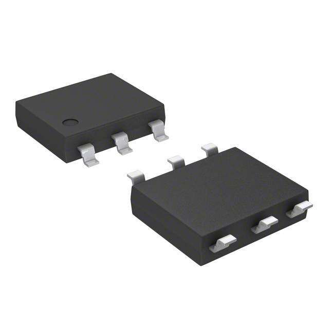
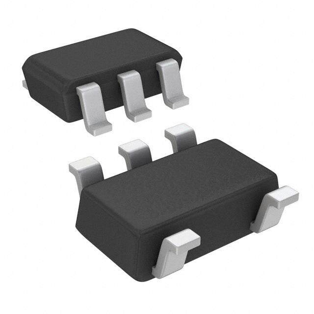
| 描述 | THYRISTOR SIDAC DSL 12V SOT23-5硅对称二端开关元件 30A 12V SOT23-5L |
| 产品分类 | |
| 品牌 | Littelfuse |
| 产品手册 | |
| 产品图片 |
|
| rohs | 符合RoHS无铅 / 符合限制有害物质指令(RoHS)规范要求 |
| 产品系列 | 晶体闸流管,硅对称二端开关元件,Littelfuse SDP0120T023G5RPSDP |
| 数据手册 | |
| 产品型号 | SDP0120T023G5RP |
| 不重复通态电流 | 50 A |
| 产品培训模块 | http://www.digikey.cn/PTM/IndividualPTM.page?site=cn&lang=zhs&ptm=23919 |
| 产品种类 | 硅对称二端开关元件 |
| 保持电流Ih最大值 | 30 mA |
| 元件数 | 1 |
| 关闭状态漏泄电流(在VDRMIDRM下) | 5 uA |
| 关闭状态电容CO | 6 pF |
| 其它名称 | F5917TR |
| 包装 | 带卷 (TR) |
| 商标 | Littelfuse |
| 商标名 | SIDACtor |
| 安装风格 | SMD/SMT |
| 封装 | Reel |
| 封装/外壳 | SC-74A,SOT-753 |
| 封装/箱体 | SOT-23-5 |
| 工作结温 | - 40 C to + 150 C |
| 工厂包装数量 | 3000 |
| 开启状态电压 | 4 V |
| 最大工作温度 | + 85 C |
| 最大转折电流IBO | 500 mA |
| 最小工作温度 | - 40 C |
| 标准包装 | 3,000 |
| 特色产品 | http://www.digikey.cn/product-highlights/cn/zh/littelfuse-sdp-series-sidactor-protection-thyristors/3885 |
| 电压-导通 | - |
| 电压-断态 | 12V |
| 电压-通态 | 4V |
| 电容 | 6pF |
| 电流-保持(Ih) | 30mA |
| 电流-峰值脉冲(10/1000µs) | - |
| 电流-峰值脉冲(8/20µs) | 50A |
| 电流额定值 | 1 A |
| 系列 | SDP Series SOT23-5 |
| 转折电流VBO | 20 V |
| 额定重复关闭状态电压VDRM | 12 V |





- 商务部:美国ITC正式对集成电路等产品启动337调查
- 曝三星4nm工艺存在良率问题 高通将骁龙8 Gen1或转产台积电
- 太阳诱电将投资9.5亿元在常州建新厂生产MLCC 预计2023年完工
- 英特尔发布欧洲新工厂建设计划 深化IDM 2.0 战略
- 台积电先进制程称霸业界 有大客户加持明年业绩稳了
- 达到5530亿美元!SIA预计今年全球半导体销售额将创下新高
- 英特尔拟将自动驾驶子公司Mobileye上市 估值或超500亿美元
- 三星加码芯片和SET,合并消费电子和移动部门,撤换高东真等 CEO
- 三星电子宣布重大人事变动 还合并消费电子和移动部门
- 海关总署:前11个月进口集成电路产品价值2.52万亿元 增长14.8%


PDF Datasheet 数据手册内容提取
SIDACtor® Protection Thyristors Teccor® brand SIDACtor® DSL Protection Devices SDP Series - SOT23-5 RoHS Pb e3 Description This new SIDACtor series thyristors are targeted for the tertiary or line driver side protection position for VDSL2+, ADSL2 applications and general I/O protection functions. This new low capacitance over voltage protection does not require a bias voltage and is sufficiently robust for the chip- side position behind the coupling transformer. This SOT23-5 solution, with its flow-through design, minimizes PCB trace layout routing, while its four different stand-off voltage values offer compatibility with a variety of line drivers. Its low capacitance makes it compatible with ADSL2 and VDSL2, and the 30MHz bandplan of VDSL2+. Agency Approvals Features & Benefits Agency Agency File Number • L ower overshooting • Starts to switch in protection than clamping nanoseconds E133083 • S OT23-5 surface mount • RoHS compliant and package Halogen-Free Schematic Symbol • L ow insertion loss • P b-free E3 means 2nd level interconnect is Pb-free and • Low capacitance the terminal finish material • B idirectional transient is tin(Sn) (IPC/JEDEC (Tip) 1 5 (Tip) voltage protection J-STD-609A.01) • R obust surge rating NC 2 Applicable Global Standards • YD/T 950 • I EC 61000-4-5 2nd edition (Ring) 3 4 (Ring) • YD/T 993 • I TU K.20/21/45 Basic Level • YD/T 1082 • I TU K.20/21/45 Enhanced Level • G R 1089 Inter-building • TIA-968-A • GR 1089 Intra-building Additional Information • TIA-968-B • IEC 61000-4-2 Datasheet Resources Samples Electrical Characteristics V@I=1.0 V @I =5µA V @250V/µs I I T T Co@f=1MHz,2V Part Number Marking DRM DRM S H S Amps V min V max mA typ mA max V max pF typ pF max SDP0080T023G5RP P8G 8 15 30 500 4.0 8.0 9.0 SDP0120T023G5RP P12G 12 20 30 500 4.0 7.8 9.0 SDP0180T023G5RP P18G 18 25 30 500 4.0 7.3 8.3 SDP0240T023G5RP P24G 24 35 30 500 4.0 5.7 6.5 Notes: - All measurement are made at an ambient temperature of 25°C. - Ipp applies to -40°C through +85°C temperature range. - Ipp is repetitive surge rating and is guaranteed for the life of the product. - SIDACtor components are bidirectional. All electrical parameters and surge rating apply to forward and reverse polarities. © 2018 Littelfuse, Inc. Specifications are subject to change without notice. Revised: 05/02/18
SIDACtor® Protection Thyristors Teccor® brand SIDACtor® DSL Protection Devices Maximum Ratings Parameter Name Symbol Test Conditions Value Units SDP0080T023G5RP 50 8/201 SDP0120T023G5RP 70 min 1.2/502 SDP0180T023G5RP 70 Lightning surge waveforms I A pp SDP0240T023G5RP 70 5/3101 min 20 10/7002 min max Operating Free Temperature Range T -40 +85 °C A Junction temperature T -40 +150 °C J Storage temperature T -40 +150 °C STG Notes: 1. Voltage waveform in µs 2.Current waveform in µs - The device also complies with IEC 61000-4-2 ESD ±15kV (air discharge), ±8 kV(contact discharge) and IEC 61000-4-4 EFT 40A(5/50nS) in equipment level ESD test when used behind the xDSL transformer. - The component must initially be in thermal equilibrium with -40°C < T < +150°C - The lightning surge may be repeated after the device returns to its initJial conditions. Mechanical dimensions, recommended layout dimensions The epoxy meets UL 94V-0 ratings. Inches Millimeters Dimension Min Max Min Max A 0.035 0.057 0.90 1.45 A A1 0 0.004 0 0.10 A2 0.035 0.051 0.90 1.30 B 0.014 0.020 0.35 0.50 0.037(0.95) C 0.004 0.008 0.09 0.20 D D 0.11 0.118 2.80 3.00 E 0.059 0.069 1.50 1.75 F 0.102 0.118 2.6 3.00 B G 0.004 0.024 0.10 0.60 E A2 A1 C G F 0.037(0.95) Dimension are in inches (and millimeters). 0.047(1.2) 0.024(0.60) 0.138(3.5) © 2018 Littelfuse, Inc. Specifications are subject to change without notice. Revised: 05/02/18
SIDACtor® Protection Thyristors Teccor® brand SIDACtor® DSL Protection Devices Thermal Considerations Package Symbol Parameter Value Unit 5 T Operating Junction Temperature Range -40 to +150 °C J 4 T Storage Temperature Range -40 to +150 °C STG 1 2 R Thermal Resistance: Junction to Ambient 120 °C/W 3 0JA Holding Current vs. Case Temperature V vs. Junction Temperature S 2.0 14 25ºC) 11..86 ge – % 1102 IH T= C 1.4 han 68 I(H 1.2 25°C C S 4 25 °C V atio of 01..08 ent of 02 R 0.6 rc -4 e P -6 0.4 -40 -20 0 20 40 60 80 100 120 140 160 -8 Case Temperature (T ) - ºC -40 -20 0 20 40 60 80 100120140 160 C Junction Temperature (T ) – °C J Capacitance vs. Bias Voltage V-I Characteristics 9 +I 8 I T F) 7 p IS e ( 6 IH c n a 5 pacit 4 SDP-08 -V IDRM +V a SDP-012 C 3 VT VDRM SDP-018 VS 2 SDP-024 1 0 0 2 4 6 8 10 12 14 16 18 20 22 24 Off-State Voltage (V) -I © 2018 Littelfuse, Inc. Specifications are subject to change without notice. Revised: 05/02/18
SIDACtor® Protection Thyristors Teccor® brand SIDACtor® DSL Protection Devices SDP-xxx Application example The following schematics show alternate protection solutions and the SDP3500Q38CB overvoltage protector. GDTs may for a typical DSL interface that connects to outside wiring. also be used on the line side of the coupling transformer. The This surface mount SOT23-5 chip-side solution provides a flow-through design of the SOT23-5 package is illustrated minimum footprint solution appropriate for high density card below. If the inter winding capacitance of the transformer is designs. The SDP-xxx0T023 will protect the interface from allowing some common mode events to get coupled across, lightning induced surges on the chip-side of the coupling then the SDP-xxx0T023 can be placed in a three chip mode, transformer. This tertiary protector may be preceded by line- as shown below for additional chip-side protection. side protection such as the TeleLink over-current protector DSL driver chipset Tip Ring SDP-018 DSL driver chipset Tip Ring (3)SDP-018 1 5 PCBTrace NC 2 3 4 PCBTrace © 2018 Littelfuse, Inc. Specifications are subject to change without notice. Revised: 05/02/18
SIDACtor® Protection Thyristors Teccor® brand SIDACtor® DSL Protection Devices Soldering Parameters Pb-Free assembly Reflow Condition (see Fig. 1) FFiigguurree 11 tt - Temperature Min (T ) +150°C TT PP s(min) PP Pre Heat - Temperature Max (Ts(max)) +200°C RRaammpp--uupp CCrriiTTttiiLLcc aattooll ZZTTooPPnnee - Time (Min to Max) (t) 60-180 secs. s TT Average ramp up rate (Liquidus Temp (TL) 3°C/sec. Max. eeTT LL ttLL to peak) rruu SS((mmaaxx)) tt TS(max) to TL - Ramp-up Rate 3°C/sec. Max. aarree RRaammpp--ddoowwnn Reflow - Temperature (TL) (Liquidus) +217°C ppmmTTSS((mmiinn)) PPrreehheeaatt - Temperature (tL) 60-150 secs. eeTT ttSS Peak Temp (T) +260(+0/-5)°C P 2255 Time within 5°C of actual Peak Temp (tp) 30 secs. Max. ttiimmee ttoo ppeeaakk tteemmppeerraattuurree TTiimmee ((tt 2255ººCC ttoo ppeeaakk)) Ramp-down Rate 6°C/sec. Max. Time 25°C to Peak Temp (T) 8 min. Max. P Do not exceed +260°C Environmental Specifications Physical Specifications Mil-STD-883, Method 1010.8 Condition C, -65°C to +150°C Temp Cycling 168 Hrs, 85°C /60%RH+3IR-Reflow, 260°C +5V, -0°C Terminal Material 100% Matte-Tin Plated JESD 22-A101 85°C , 85°CRH. 50V Bias Humidity 168 Hrs, 85°C /60%RH+3IR-Reflow, Solderability EIA J-STD-002, TEST A. 260°C +5V, -0°C JEDEC 22-A102 No Bias, 121°C, 100%RH 96Hrs/192Hrs. Pressure Cooker 168 Hrs, 85°C /60%RH+3IR-Reflow, 260°C +5V, -0°C High Temp Storage JESD 22-A103 Con B. 150°C, no bias 1000Hrs JESD 22-108 HTRB 168 Hrs, 85°C /60%RH+3IR-Reflow, 260°C +5V, -0°C Mil-STD-883, Method 1011.9 Condition A, 0°C to 100°C Thermal Shock 168 Hrs, 85°C /60%RH+3IR-Reflow, 260°C +5V, -0°C As per flow, JSTD-020 pre&post preconditioning C-SAM test. Wet Humidity NEMI standard: 60°C/93%RH (Tin only) Part Numbering Part Marking SDPxxx0T023G 5RP 5 4 Type Packing Option SIDACtor DSL Protector RP: Reel Pack Nominal Working voltage: PXXG Part Marking Code 008=8V Number of pins 012=12V 018=18V 024=24V Surge Ipp rating 1 2 3 Construction variable: 0=single chip Pin 1 indicator Package T023=SOT23-5 © 2018 Littelfuse, Inc. Specifications are subject to change without notice. Revised: 05/02/18
SIDACtor® Protection Thyristors Teccor® brand SIDACtor® DSL Protection Devices Packing Options Package Type Description Quantity Added Suffix Min. Order Qty. Industry Standard SOT23-5 T023 3000 RP 3000 EIA-481-A Tape & Reel Pack Tape and Reel Specification — SOT23-5 (cid:66)(cid:68)(cid:68)(cid:70)(cid:84)(cid:84)(cid:33)(cid:73)(cid:80)(cid:77)(cid:70) (cid:53)(cid:47)(cid:49)(cid:110)(cid:110) (cid:50)(cid:53)(cid:47)(cid:53)(cid:110)(cid:110) (cid:50)(cid:47)(cid:54)(cid:110)(cid:110) (cid:51)(cid:47)(cid:49)(cid:110)(cid:110) (cid:50)(cid:47)(cid:56)(cid:54)(cid:110)(cid:110) (cid:69)(cid:74)(cid:66)(cid:47)(cid:33)(cid:73)(cid:80)(cid:77)(cid:70) (cid:50)(cid:52)(cid:110)(cid:110) (cid:57)(cid:110)(cid:110) (cid:68)(cid:77) (cid:50)(cid:57)(cid:49)(cid:110)(cid:110) (cid:55)(cid:49)(cid:110)(cid:110) (cid:53)(cid:47)(cid:49)(cid:110)(cid:110) (cid:84)(cid:80)(cid:85)(cid:51)(cid:52)(cid:46)(cid:54)(cid:33)(cid:41)(cid:57)(cid:110)(cid:110)(cid:33)(cid:81)(cid:80)(cid:68)(cid:76)(cid:70)(cid:85)(cid:33)(cid:81)(cid:74)(cid:85)(cid:68)(cid:73)(cid:42) (cid:57)(cid:47)(cid:53)(cid:110)(cid:110) (cid:86)(cid:84)(cid:70)(cid:83)(cid:33)(cid:69)(cid:74)(cid:83)(cid:70)(cid:68)(cid:85)(cid:74)(cid:80)(cid:79)(cid:33)(cid:80)(cid:71)(cid:33)(cid:71)(cid:70)(cid:70)(cid:69) (cid:81)(cid:74)(cid:79)(cid:33)(cid:50) (cid:72)(cid:70)(cid:79)(cid:70)(cid:83)(cid:66)(cid:77)(cid:33)(cid:74)(cid:79)(cid:71)(cid:80)(cid:83)(cid:78)(cid:66)(cid:85)(cid:74)(cid:80)(cid:79) (cid:50)(cid:47)(cid:33)(cid:52)(cid:49)(cid:49)(cid:49)(cid:33)(cid:81)(cid:74)(cid:70)(cid:68)(cid:70)(cid:84)(cid:33)(cid:81)(cid:70)(cid:83)(cid:33)(cid:83)(cid:70)(cid:70)(cid:77)(cid:47) (cid:51)(cid:47)(cid:33)(cid:80)(cid:83)(cid:69)(cid:70)(cid:83)(cid:33)(cid:74)(cid:79)(cid:33)(cid:78)(cid:86)(cid:77)(cid:85)(cid:74)(cid:81)(cid:77)(cid:70)(cid:84)(cid:33)(cid:80)(cid:71)(cid:33)(cid:71)(cid:86)(cid:77)(cid:77)(cid:33)(cid:83)(cid:70)(cid:70)(cid:77)(cid:84)(cid:33)(cid:80)(cid:79)(cid:77)(cid:90)(cid:47) (cid:68)(cid:80)(cid:87)(cid:70)(cid:83)(cid:33)(cid:85)(cid:66)(cid:81)(cid:70) Disclaimer Notice - Information furnished is believed to be accurate and reliable. However, users should independently evaluate the suitability of and test each product selected for their own applications. Littelfuse products are not designed for, and may not be used in, all applications. Read complete Disclaimer Notice at www.littelfuse.com/disclaimer-electronics. © 2018 Littelfuse, Inc. Specifications are subject to change without notice. Revised: 05/02/18
 Datasheet下载
