- 型号: SCRN248R-F
- 制造商: Cornell Dubilier
- 库位|库存: xxxx|xxxx
- 要求:
| 数量阶梯 | 香港交货 | 国内含税 |
| +xxxx | $xxxx | ¥xxxx |
查看当月历史价格
查看今年历史价格
SCRN248R-F产品简介:
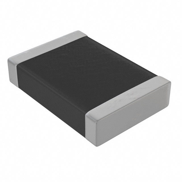
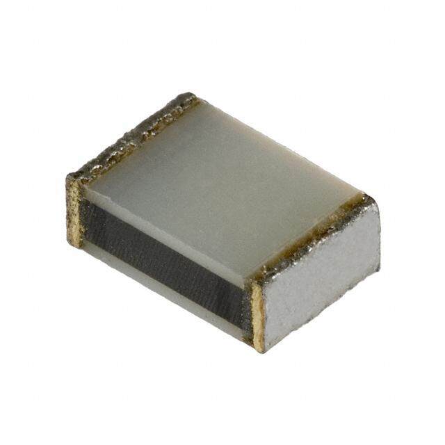
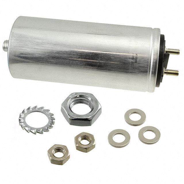
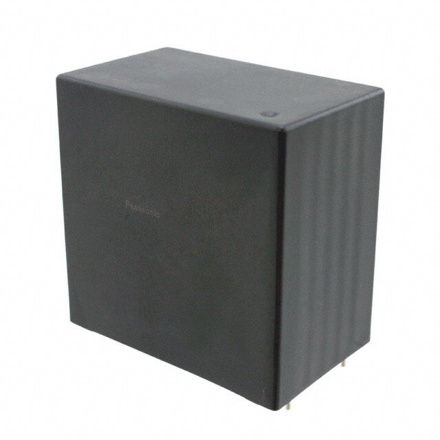
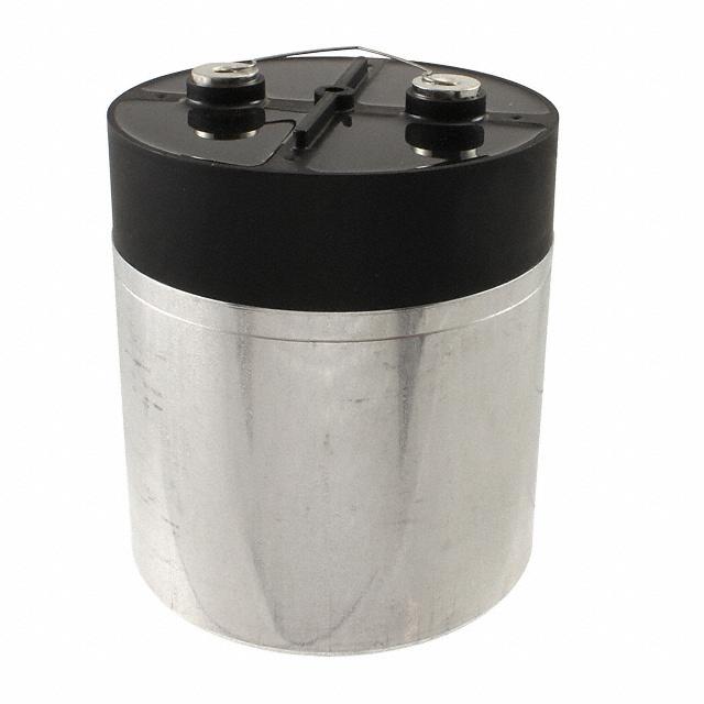
ICGOO电子元器件商城为您提供SCRN248R-F由Cornell Dubilier设计生产,在icgoo商城现货销售,并且可以通过原厂、代理商等渠道进行代购。 SCRN248R-F价格参考¥420.16-¥475.80。Cornell DubilierSCRN248R-F封装/规格:薄膜电容器, 1µF 薄膜电容器 2000Vpk(2KVPK) 纸,金属化 径向,Can。您可以下载SCRN248R-F参考资料、Datasheet数据手册功能说明书,资料中有SCRN248R-F 详细功能的应用电路图电压和使用方法及教程。
| 参数 | 数值 |
| 产品目录 | |
| 描述 | CAP FILM 1UF 2KVAC SCREW薄膜电容器 1uF 2000Vpk 10% |
| ESR(等效串联电阻) | - |
| 产品分类 | |
| 品牌 | Cornell Dubilier Electronics (CDE) |
| 产品手册 | |
| 产品图片 |
|
| rohs | 符合RoHS无铅 / 符合限制有害物质指令(RoHS)规范要求 |
| 产品系列 | 薄膜电容器,Cornell Dubilier SCRN248R-FSCR |
| 数据手册 | |
| 产品型号 | SCRN248R-F |
| 产品 | AC and Pulse Film Capacitors |
| 产品种类 | |
| 介电材料 | 纸,金属化 |
| 其它名称 | 338-3588 |
| 包装 | 散装 |
| 商标 | Cornell Dubilier |
| 外壳宽度 | 2.16 in |
| 外壳长度 | 3.13 in |
| 外壳高度 | 1.31 in |
| 大小/尺寸 | 2.160" 长 x 1.310" 宽 (54.86mm x 33.27mm),唇状 |
| 安装类型 | 机架安装,需要支架/托架 |
| 容差 | ±10% |
| 封装 | Bulk |
| 封装/外壳 | 径向,Can - 螺丝端子 |
| 工作温度 | -40°C ~ 65°C |
| 应用 | 高频率, 开关 |
| 引线间距 | 0.810"(20.57mm) |
| 引线间隔 | 0.81 in |
| 标准包装 | 1 |
| 特性 | - |
| 电介质 | Paper |
| 电压额定值DC | 2 kV |
| 电容 | 1.0µF |
| 电流额定值 | 60 A |
| 端接 | 螺钉端子 |
| 端接类型 | Stud Threaded |
| 类型 | Type SCRN Film-Paper/Extended Foil Commutating Capacitor |
| 系列 | SCR |
| 额定电压-AC | 2000Vpk(2kV) |
| 额定电压-DC | - |
| 高度-安装(最大值) | 3.190"(81.03mm) |



- 商务部:美国ITC正式对集成电路等产品启动337调查
- 曝三星4nm工艺存在良率问题 高通将骁龙8 Gen1或转产台积电
- 太阳诱电将投资9.5亿元在常州建新厂生产MLCC 预计2023年完工
- 英特尔发布欧洲新工厂建设计划 深化IDM 2.0 战略
- 台积电先进制程称霸业界 有大客户加持明年业绩稳了
- 达到5530亿美元!SIA预计今年全球半导体销售额将创下新高
- 英特尔拟将自动驾驶子公司Mobileye上市 估值或超500亿美元
- 三星加码芯片和SET,合并消费电子和移动部门,撤换高东真等 CEO
- 三星电子宣布重大人事变动 还合并消费电子和移动部门
- 海关总署:前11个月进口集成电路产品价值2.52万亿元 增长14.8%
PDF Datasheet 数据手册内容提取
Type SCR, Commutating Capacitors Type SCRN Film-Paper/Extended Foil Commutating Capacitor Type SCRN capacitors are for SCR (silicon controlled rectifer) commutating applications that require high peak and rms current capability. These capacitors are ideal for other high frequency and pulsed applications. The SCRN is supplied in oval or rectangular metal cases with 1/4 x 20 threaded stud and insulated terminals to withstand high current and high peak voltages. Highlights - Conforms to EIA RS401 for power semiconductor applications - Non ferrous covers available for high frequency applications - 40,000 hours life at full rated voltage and temperature - High voltage, high current and high frequency Specifcations - Custom designs available Capacitance Range 0.25 µF to 50.0 µF Capacitance Tolerance ±10% Rated Voltage 200 Vpk to 2000 Vpk Operating Temperature Range –40 ºC to +80 ºC Maximum rms Current Case codes: A, B, C, D = 60 Irms max. E and F = 100 Irms max. Maximum rms Voltage see application guide Test Voltage between Terminal @ 25ºC DC voltage 2 x rated peak for 60 s Test Voltage between Terminals & Case @ 25ºC 2 x reference AC voltage +1000 Vac for 60 s Life Test EIA RS401 Life Expectancy 40,000 h life at full rated voltage, current, case temperature and VA Reliability Minimum of 95% survival Standards EIA RS401 Rohs Compliant Dimensions Construction Details Case Material Tin Plated Steel or Aluminum B Encapsulation Biodegradeable, Environmentally B ±0.03" Compatible Fluid ±±00..0063”" Terminal Material Electro-tin plated copper stud and molded pillar insulator A A ±±00..0036"” ±0.03" F ±0.03" F ¼ - 20 THD ±0.03" ¼ - 20 THD 2 places 2 places C C ±0.06" ±0.06" D D ±0.06" ±0.06" Case Dimensions Inches H ±+00..0162”" H Code A B C D F H Figure -0.06” ±0.06" A 1.31 2.16 0.56 1.19 0.81 see table Fig. 1 B 1.56 2.69 0.50 1.13 1.25 see table Fig. 1 C 1.91 2.91 0.50 1.13 1.38 see table Fig. 1 D 1.97 3.66 0.50 1.13 1.38 see table Fig. 1 E 2.84 4.56 0.50 1.13 2.00 see table Fig. 2 Figure 1 Figure 2 F 3.75 4.56 0.56 1.19 2.00 see table Fig. 2 CDE Cornell Dubilier • 1605 E. Rodney French Blvd. • New Bedford, MA 02744 • Phone: (508)996-8561 • Fax: (508)996-3830
Type SCR, Commutating Capacitors Type SCRN Film-Paper/Extended Foil Commutating Capacitor Ratings Cap Catalog Case H Max VA Max Cap Catalog Case H Max VA Max (µF) Part Number Code (Inches) (65 ºC) (Arms) (µF) Part Number Code (Inches) (65 ºC) (Arms) 200 Vpk (Paper Dielectric) 600 Vpk (Film Dielectric for Low-loss) 3 SCRN201R-F A 2.13 400 60 1 SCRN262R-F A 2.38 2200 60 5 SCRN202R-F A 2.63 465 60 2 SCRN263R-F A 2.38 2060 60 10 SCRN203R-F A 3.88 625 60 3 SCRN264R-F A 3.88 3190 60 15 SCRN205R-F A 4.75 765 60 5 SCRN265R-F A 4.25 4380 60 20 SCRN206R-F B 4.25 875 60 10 SCRN266R-F C 4.25 6060 60 30 SCRN208R-F C 5.25 1200 60 1000 Vpk (Film and Paper Dielectric) 40 SCRN209R-F C 6.75 1500 60 1 SCRN233R-F A 2.13 790 60 50 SCRN210R-F D 5.75 1590 60 2 SCRN234R-F A 3.13 1070 60 400 Vpk (Film and Paper Dielectric) 3 SCRN235R-F A 3.88 1455 60 2 SCRN211R-F A 2.63 790 60 5 SCRN236R-F B 4.25 1785 60 3 SCRN212R-F A 2.63 970 60 10 SCRN237R-F C 5.75 2570 60 5 SCRN213R-F A 3.88 1130 60 15 SCRN238R-F D 5.75 3170 60 10 SCRN214R-F B 4.75 1930 60 20 SCRN239R-F E 5.13 5200 100 15 SCRN215R-F C 4.75 2240 60 1500 Vpk (Film and Paper Dielectric) 20 SCRN216R-F C 6.25 2800 60 .5 SCRN240R-F A 2.13 990 60 30 SCRN217R-F D 6.75 3720 60 1 SCRN241R-F A 2.88 1240 60 40 SCRN218R-F D 8.00 4330 60 2 SCRN242R-F B 3.50 1890 60 50 SCRN219R-F E 6.25 6050 100 3 SCRN243R-F C 4.25 2550 60 600 Vpk (Film and Paper Dielectric) 5 SCRN244R-F C 5.75 3250 60 2 SCRN220R-F A 2.63 815 60 10 SCRN245R-F E 5.13 6500 100 3 SCRN221R-F A 3.13 1200 60 2000 Vpk (Film and Paper Dielectric) 5 SCRN222R-F A 4.25 1420 60 .25 SCRN246R-F A 2.13 990 60 10 SCRN224R-F C 4.25 2040 60 .33 SCRN257R-F A 2.13 1000 60 15 SCRN226R-F C 5.75 2800 60 .5 SCRN247R-F A 2.63 1180 60 20 SCRN227R-F D 5.75 3260 60 1 SCRN248R-F A 3.13 1300 60 25 SCRN229R-F D 6.75 3720 60 2 SCRN249R-F B 4.25 2230 60 30 SCRN230R-F D 8.00 4330 60 3 SCRN251R-F C 4.75 2800 60 40 SCRN231R-F E 6.25 6060 100 5 SCRN253R-F D 5.75 4020 60 50 SCRN232R-F E 7.25 6850 100 10 SCRN256R-F F 5.75 7600 100 CDE Cornell Dubilier • 1605 E. Rodney French Blvd. • New Bedford, MA 02744 • Phone: (508)996-8561 • Fax: (508)996-3830
Type SCR, Commutating Capacitors Type SCRN Film-Paper/Extended Foil Commutating Capacitor Application Guide How to Choose a Commutating Capacitor 1. From circuit analysis or measurement, determine application values for these six parameters: 3. Check that your application’s rms current is no more than the capacitor’s Max. Amps RMS. You can calculate the current from your Vrms using the Nominal capacitance in µF equations in the following section. Current pulse width in µs Current pulse period in µs 4. Check that your application’s volt-amperes is not more than the Maximum peak voltage capacitor’s VA capability. The VA capability is the max VA rating times Continuous AC voltage in Vrms the Volt-Ampere multiplier from Figure 2 (Current Pulse Width) and that Maximum volt-amps (VA) times the Volt-Ampere Multiplier from Figure 3 (Ambient Temperature). See the following section for more on using volt-ampere multipliers. 2. Choose a capacitor from the ratings table of the desired nominal capacitance with a peak voltage rating no less than your maximum If you need a greater VA capability, repeat these steps for a higher peak peak voltage. voltage capacitor or consider connecting units in parallel to divide the VA required. For up to peak voltage of 600 V, you may also consider polypropylene flm dielectric units, Catalog Numbers SCRN262R through SCRN266R, with higher VA capability. Using Volt-Ampere Ratings Pulse Wave Applications V peak The capacitors maximum VA rating is the maximum product of the Voltage sine wave voltage and current that may be applied at 65 ºC without overheating the capacitor and reducing its expected life. For other ΔV temperatures and pulsed current, use the multipliers of Figures 2 and 3 to derate the Max VA rating. T The Max Amps RMS rating is set by the capability of the capacitor terminals. Exceeding this limit can damage the terminals and cause capacitor failure. Calculate the capacitor’s actual VA load as the product of the rms voltage Current across the capacitor and the rms current through the capacitor. To I peak calculate rms current for an applied sine wave or squarewave voltage, use these equations. Figure 1 For a sinewave voltage the current is: Irms = 2π fCVrmsX10-6 and for a squarewave the current is: Irms = C∆V/[0.64(tT)0.5] = Ipeak(t/T)0.5 where (f ) is repetition frequency in Hz, C is nominal capacitance in µF, ∆V the peak-to-peak squarewave amplitude in volts, (t) is the pulse width in µs and T is the pulse period in µs. The peak current for the square wave voltage is: Ipeak = C∆V/0.64t CDE Cornell Dubilier • 1605 E. Rodney French Blvd. • New Bedford, MA 02744 • Phone: (508)996-8561 • Fax: (508)996-3830
Notice and Disclaimer: All product drawings, descriptions, specifcations, statements, information and data (collectively, the “Information”) in this datasheet or other publication are subject to change. The customer is responsible for checking, confrming and verifying the extent to which the Information con- tained in this datasheet or other publication is applicable to an order at the time the order is placed. All Information given herein is believed to be accurate and reliable, but it is presented without any guaran- tee, warranty, representation or responsibility of any kind, expressed or implied. Statements of suitability for certain applications are based on the knowledge that the Cornell Dubilier company providing such statements (“Cornell Dubilier”) has of operating conditions that such Cornell Dubilier company regards as typical for such applications, but are not intended to constitute any guarantee, warranty or representa- tion regarding any such matter – and Cornell Dubilier specifcally and expressly disclaims any guarantee, warranty or representation concerning the suitability for a specifc customer application, use, storage, transportation, or operating environment. The Information is intended for use only by customers who have the requisite experience and capability to determine the correct products for their application. Any technical advice inferred from this Information or otherwise provided by Cornell Dubilier with reference to the use of any Cornell Dubilier products is given gratis (unless otherwise specifed by Cornell Dubilier), and Cornell Dubilier assumes no obligation or liability for the advice given or results obtained. Although Cornell Dubilier strives to apply the most stringent quality and safety standards regarding the design and manufacturing of its products, in light of the current state of the art, isolated component failures may still occur. Accordingly, customer applications which require a high degree of reliability or safety should employ suitable designs or other safeguards (such as installation of protective circuitry or redundancies or other appropriate protective measures) in order to ensure that the failure of an electrical component does not result in a risk of personal injury or property damage. Although all product-related warnings, cautions and notes must be observed, the customer should not assume that all safety measures are indi- cated in such warnings, cautions and notes, or that other safety measures may not be required.
/SCRN248R-F.jpg)
 Datasheet下载
