ICGOO在线商城 > 集成电路(IC) > 嵌入式 - 微控制器 > S87C51RC24
- 型号: S87C51RC24
- 制造商: Intel
- 库位|库存: xxxx|xxxx
- 要求:
| 数量阶梯 | 香港交货 | 国内含税 |
| +xxxx | $xxxx | ¥xxxx |
查看当月历史价格
查看今年历史价格
S87C51RC24产品简介:
ICGOO电子元器件商城为您提供S87C51RC24由Intel设计生产,在icgoo商城现货销售,并且可以通过原厂、代理商等渠道进行代购。 S87C51RC24价格参考。IntelS87C51RC24封装/规格:嵌入式 - 微控制器, MCS 51 微控制器 IC 87C 8-位 24MHz 32KB(32K x 8) OTP 。您可以下载S87C51RC24参考资料、Datasheet数据手册功能说明书,资料中有S87C51RC24 详细功能的应用电路图电压和使用方法及教程。
| 参数 | 数值 |
| 产品目录 | 集成电路 (IC) |
| 描述 | IC MCU 8BIT 32K 24MHZ OTP 44MQFP |
| EEPROM容量 | - |
| 产品分类 | |
| I/O数 | 32 |
| 品牌 | Intel |
| 数据手册 | |
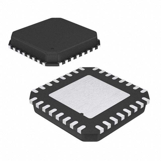
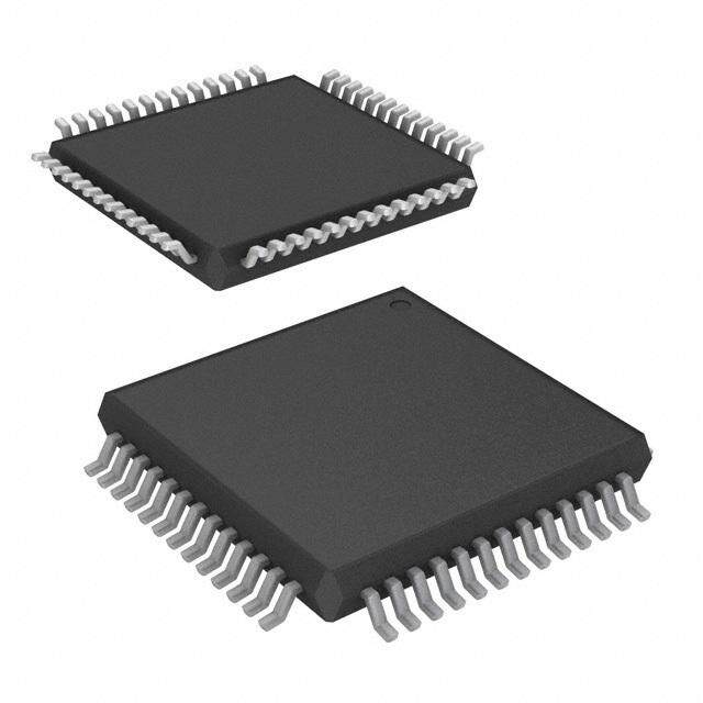
| 产品图片 |
|
| 产品型号 | S87C51RC24 |
| RAM容量 | 512 x 8 |
| rohs | 不符合限制有害物质指令(RoHS)规范要求 |
| 产品系列 | 87C |
| 产品目录页面 | |
| 供应商器件封装 | - |
| 其它名称 | 800375 |
| 包装 | 托盘 |
| 外设 | WDT |
| 封装/外壳 | 44-QFP |
| 工作温度 | 0°C ~ 70°C |
| 振荡器类型 | 外部 |
| 数据转换器 | - |
| 标准包装 | 96 |
| 核心处理器 | MCS 51 |
| 核心尺寸 | 8-位 |
| 电压-电源(Vcc/Vdd) | 4.5 V ~ 5.5 V |
| 程序存储器类型 | OTP |
| 程序存储容量 | 32KB(32K x 8) |
| 连接性 | SIO |
| 速度 | 24MHz |




- 商务部:美国ITC正式对集成电路等产品启动337调查
- 曝三星4nm工艺存在良率问题 高通将骁龙8 Gen1或转产台积电
- 太阳诱电将投资9.5亿元在常州建新厂生产MLCC 预计2023年完工
- 英特尔发布欧洲新工厂建设计划 深化IDM 2.0 战略
- 台积电先进制程称霸业界 有大客户加持明年业绩稳了
- 达到5530亿美元!SIA预计今年全球半导体销售额将创下新高
- 英特尔拟将自动驾驶子公司Mobileye上市 估值或超500亿美元
- 三星加码芯片和SET,合并消费电子和移动部门,撤换高东真等 CEO
- 三星电子宣布重大人事变动 还合并消费电子和移动部门
- 海关总署:前11个月进口集成电路产品价值2.52万亿元 增长14.8%

PDF Datasheet 数据手册内容提取
8XC51RA(cid:47)RB(cid:47)RC CHMOS SINGLE-CHIP 8-BIT MICROCONTROLLER Commercial(cid:47)Express 87C51RA(cid:47)83C51RA(cid:47)80C51RA(cid:47)87C51RB(cid:47)83C51RB(cid:47)87C51RC(cid:47)83C51RC (cid:42)SeeTable1forProliferationOptions Y HighPerformanceCHMOSEPROM(cid:47) Y 6InterruptSources ROM(cid:47)CPU Y ProgrammableSerialChannelwith(cid:58) Y 24MHzOperation (cid:208)FramingErrorDetection (cid:208)AutomaticAddressRecognition Y 512BytesofOn-ChipDataRAM Y TTLandCMOSCompatibleLogic Y DedicatedHardwareWatchdogTimer Levels (One-TimeEnabledwithReset-Out) Y 64KExternalProgramMemorySpace Y Three16-BitTimer(cid:47)Counters Y 64KExternalDataMemorySpace Y ProgrammableClockOut Y MCS(cid:201) 51CompatibleInstructionSet Y Up(cid:47)DownTimer(cid:47)Counter Y PowerSavingIdleandPowerDown Y ThreeLevelProgramLockSystem Modes Y 8K(cid:47)16K(cid:47)32KOn-ChipProgramMemory Y ONCE(On-CircuitEmulation)Mode Y ImprovedQuickPulseProgramming Y Four-LevelInterruptPriority Algorithm Y ExtendedTemperatureRange Y BooleanProcessor (b40(cid:167)Cto a85(cid:167)C) Y 32ProgrammableI(cid:47)OLines MEMORY ORGANIZATION ROMless ROM EPROM ROM(cid:47)EPROM RAM Device Device Version Bytes Bytes 80C51RA 83C51RA 87C51RA 8K 512 80C51RA 83C51RB 87C51RB 16K 512 80C51RA 83C51RC 87C51RC 32K 512 Thesedevicescanaddressupto64Kbytesofexternalprogram(cid:47)datamemory(cid:46) TheIntel8XC51RA(cid:47)8XC51RB(cid:47)8XC51RCisasingle-chipcontrol-orientedmicrocontrollerwhichisfabricated on Intel’s reliable CHMOS III-E technology(cid:46) Being a member of the MCS 51 family of controllers(cid:44) the 8XC51RA(cid:47)8XC51RB(cid:47)8XC51RCusesthesamepowerfulinstructionset(cid:44)hasthesamearchitecture(cid:44)andispin- for-pin compatible with the existing MCS 51 family of products(cid:46) The 8XC51RA(cid:47)8XC51RB(cid:47)8XC51RC is an enhancedversionofthe8XC52(cid:47)8XC54(cid:47)8XC58(cid:46)Theaddedfeaturesmakeitanevenmorepowerfulmicrocon- trollerforapplicationsthatrequire512bytesofon-chipdataRAManddedicatedhardwareWatchDogTimer withreset-outfeatures(cid:46) Throughoutthisdocument8XC51RXwillrefertothe8XC51RA(cid:44)8XC51RBand8XC51RCunlessinformation appliestoaspecificdevice(cid:46) Foradetaileddescriptionof8XC51RA(cid:47)RB(cid:47)RC(cid:44)refertothe8XC51RA(cid:47)RB(cid:47)RCHardwareDescription(cid:44)order number272668(cid:46) (cid:42)Otherbrandsandnamesarethepropertyoftheirrespectiveowners(cid:46) InformationinthisdocumentisprovidedinconnectionwithIntelproducts(cid:46)Intelassumesnoliabilitywhatsoever(cid:44)includinginfringementofanypatentor copyright(cid:44)forsaleanduseofIntelproductsexceptasprovidedinIntel’sTermsandConditionsofSaleforsuchproducts(cid:46)Intelretainstherighttomake changestothesespecificationsatanytime(cid:44)withoutnotice(cid:46)MicrocomputerProductsmayhaveminorvariationstothisspecificationknownaserrata(cid:46) COPYRIGHT(cid:169)INTELCORPORATION(cid:44)1995 December1995 OrderNumber(cid:58)272659-002
8XC51RA(cid:47)RB(cid:47)RC Table1(cid:46)ProliferationsOptions Standard(cid:42)1 -1 -20 -24 NOTES(cid:58) (cid:42)1 3(cid:46)5MHzto12MHz(cid:59)5Vg20% 80C51RA X X X X -1 3(cid:46)5MHzto16MHz(cid:59)5Vg20% -20 3(cid:46)5MHzto20MHz(cid:59)5Vg20% 83C51RA X X X X -24 3(cid:46)5MHzto24MHz(cid:59)5Vg10% 87C51RA X X X X 83C51RB X X X X 87C51RB X X X X 83C51RC X X X X 87C51RC X X X X 272659–4 Figure1(cid:46)8XC51RXBlockDiagram 2
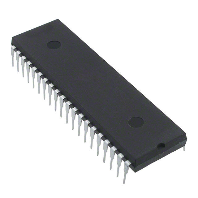
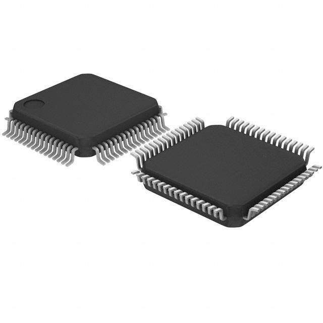
8XC51RA(cid:47)RB(cid:47)RC PROCESSINFORMATION PACKAGES ThisdeviceismanufacturedonP629(cid:46)5(cid:44) aCHMOS Part Prefix PackageType III-Eprocess(cid:46)Additionalprocessandreliabilityinfor- 8XC51RX P 40-PinPlasticDIP(OTP) mationisavailable in the Intel ® Quality System 8XC51RX N 44-PinPLCC(OTP) Handbook. 8XC51RX S 44-PinQFP(OTP) 272659–2 PLCC 272659–1 DIP 272659–3 (cid:42)Donotconnectreservedpins(cid:46) QFP Figure2(cid:46)PinConnections 3
8XC51RA(cid:47)RB(cid:47)RC PIN DESCRIPTIONS LS TTL inputs(cid:46) Port 2 pins that have 1’s written to themarepulledhighbytheinternalpullups(cid:44)andin VCC(cid:58)Supplyvoltage(cid:46) that state can be used as inputs(cid:46) As inputs(cid:44) Port 2 pinsthatareexternallypulledlowwillsourcecurrent VSS(cid:58)Circuitground(cid:46) (IIL(cid:44)onthedatasheet)becauseoftheinternalpull- ups(cid:46) VSS1(cid:58) Secondary ground (not on DIP)(cid:46) Provided to reduce ground bounce and improve power supply Port 2 emits the high-order address byte during by-passing(cid:46) fetches from external Program Memory and during accesses to external Data Memory that use 16-bit NOTE(cid:58) addresses (MOVX (cid:64)DPTR)(cid:46) In this application it ThispinisnotasubstitutefortheVSSpin(pin22)(cid:46) usesstronginternalpullupswhenemitting1’s(cid:46)Dur- (Connectionnotnecessaryforproperoperation(cid:46)) ingaccessestoexternalDataMemorythatuse8-bit addresses(MOVX(cid:64)Ri)(cid:44)Port2emitsthecontentsof Port 0(cid:58) Port 0 is an 8-bit(cid:44) open drain(cid:44) bidirectional theP2SpecialFunctionRegister(cid:46) I(cid:47)Oport(cid:46)Asanoutputporteachpincansinkseveral SomePort2pinsreceivethehigh-orderaddressbits LS TTL inputs(cid:46) Port 0 pins that have 1’s written to during EPROM programming and program verifica- themfloat(cid:44)andinthatstatecanbeusedashigh-im- tion(cid:46) pedanceinputs(cid:46) Port 3(cid:58) Port 3 is an 8-bit bidirectional I(cid:47)O port with Port0isalsothemultiplexedlow-orderaddressand internalpullups(cid:46)ThePort3outputbufferscandrive data bus during accesses to external Program and LS TTL inputs(cid:46) Port 3 pins that have 1’s written to DataMemory(cid:46)Inthisapplicationitusesstronginter- themarepulledhighbytheinternalpullups(cid:44)andin nal pullups when emitting 1’s(cid:44) and can source and that state can be used as inputs(cid:46) As inputs(cid:44) Port 3 sinkseveralLSTTLinputs(cid:46) pinsthatareexternallypulledlowwillsourcecurrent Port0alsoreceivesthecodebytesduringEPROM (IIL(cid:44)onthedatasheet)becauseofthepullups(cid:46) programming(cid:44) and outputs the code bytes during Port 3 also serves the functions of various special programverification(cid:46)Externalpullupresistorsarere- featuresofthe8051Family(cid:44)aslistedbelow(cid:58) quiredduringprogramverification(cid:46) Port 1(cid:58) Port 1 is an 8-bit bidirectional I(cid:47)O port with PortPin AlternateFunction internalpullups(cid:46)ThePort1outputbufferscandrive P3(cid:46)0 RXD(serialinputport) LS TTL inputs(cid:46) Port 1 pins that have 1’s written to P3(cid:46)1 TXD(serialoutputport) themarepulledhighbytheinternalpullups(cid:44)andin P3(cid:46)2 INT0(externalinterrupt0) that state can be used as inputs(cid:46) As inputs(cid:44) Port 1 pinsthatareexternallypulledlowwillsourcecurrent P3(cid:46)3 INT1(externalinterrupt1) (IIL(cid:44)onthedatasheet)becauseoftheinternalpull- P3(cid:46)4 T0(Timer0externalinput) ups(cid:46) P3(cid:46)5 T1(Timer1externalinput) P3(cid:46)6 WR(externaldatamemorywritestrobe) Inaddition(cid:44)Port1servesthefunctionsofthefollow- P3(cid:46)7 RD(externaldatamemoryreadstrobe) ingspecialfeaturesofthe8XC51RX(cid:58) RST(cid:58)ResetI(cid:47)O(cid:46)Ahighonthispinfortwomachine PortPin AlternateFunction cycles while the oscillator is running resets the de- vice(cid:46)Theportpinswillbedriventotheirresetcondi- P1(cid:46)0 T2(ExternalCountInputtoTimer(cid:47) Counter2)(cid:44)Clock-Out tionwhenaminimumVIHIvoltageisappliedwhether theoscillatorisrunningornot(cid:46)Aninternalpulldown P1(cid:46)1 T2EX(Timer(cid:47)Counter2Capture(cid:47) resistorpermitsapower-onresetwithonlyacapaci- ReloadTriggerandDirectionControl) torconnectedtoVCC(cid:46)AfteraWatchDogTimerover- flow(cid:44)thisRSTpinwilldriveanoutputhighpulseata Port 1 receives the low-order address bytes during minimumVOH2for96xTOSCdurationwhilethein- EPROMprogrammingandverifying(cid:46) ternalresetsignalisactive(cid:46) ALE(cid:58)AddressLatchEnableoutputpulseforlatching Port 2(cid:58) Port 2 is an 8-bit bidirectional I(cid:47)O port with thelowbyteoftheaddressduringaccessestoex- internalpullups(cid:46)ThePort2outputbufferscandrive 4
8XC51RA(cid:47)RB(cid:47)RC ternal memory(cid:46) This pin (ALE(cid:47)PROG) is also the ured for use as an on-chip oscillator(cid:44) as shown in programpulseinputduringEPROMprogrammingfor Figure3(cid:46)Eitheraquartzcrystalorceramicresonator the87C51RX(cid:46) maybeused(cid:46)Moredetailedinformationconcerning theuseoftheon-chiposcillatorisavailableinAppli- In normal operation ALE is emitted at a constant cation Note AP-155(cid:44) ‘‘Oscillators for Microcontrol- rateof(cid:40)(cid:47)(cid:54)theoscillatorfrequency(cid:44)andmaybeused lers’’(cid:44)OrderNo(cid:46)230659(cid:46) forexternaltimingorclockingpurposes(cid:46)Note(cid:44)how- ever(cid:44)thatoneALEpulseisskippedduringeachac- cesstoexternalDataMemory(cid:46) Ifdesired(cid:44)ALEoperationcanbedisabledbysetting bit0ofSFRlocation8EH(cid:46)Withthisbitset(cid:44)thepinis weakly pulled high(cid:46) However(cid:44) the ALE disable fea- turewillbesuspendedduringaMOVXorMOVCin- 272659–5 struction(cid:44) idle mode(cid:44) power down mode and ICE C1(cid:44)C2e30pFg10pFforCrystals mode(cid:46)TheALEdisablefeaturewillbeterminatedby For Ceramic Resonators(cid:44) contact resonator manufac- reset(cid:46)WhentheALEdisablefeatureissuspendedor turer(cid:46) terminated(cid:44)theALEpinwillnolongerbepulledup weakly(cid:46) Setting the ALE-disable bit has no affect if Figure3(cid:46)OscillatorConnections themicrocontrollerisinexternalexecutionmode(cid:46) To drive the device from an external clock source(cid:44) Throughout the remainder of this data sheet(cid:44) ALE XTAL1 should be driven(cid:44) while XTAL2 floats(cid:44) as willrefertothesignalcomingoutoftheALE(cid:47)PROG showninFigure4(cid:46)Therearenorequirementsonthe pin(cid:44)andthepinwillbereferredtoastheALE(cid:47)PROG dutycycleoftheexternalclocksignal(cid:44)sincethein- pin(cid:46) puttotheinternalclockingcircuitryisthroughadi- vide-by-two flip-flop(cid:44) but minimum and maximum PSEN(cid:58) Program Store Enable is the read strobe to highandlowtimesspecifiedonthedatasheetmust externalProgramMemory(cid:46) beobserved(cid:46) Whenthe8XC51RXisexecutingcodefromexternal Anexternaloscillatormayencounterasmuchasa Program Memory(cid:44) PSEN is activated twice each 100pFloadatXTAL1whenitstartsup(cid:46)Thisisdue machine cycle(cid:44) except that two PSEN activations tointeractionbetweentheamplifieranditsfeedback are skipped during each access to external Data capacitance(cid:46)OncetheexternalsignalmeetstheVIL Memory(cid:46) and VIH specifications the capacitance will not ex- ceed20pF(cid:46) EA(cid:47)VPP(cid:58) External Access enable(cid:46) EA must be strapped to VSS in order to enable the device to fetchcodefromexternalProgramMemorylocations 0000Hto0FFFFH(cid:46)Note(cid:44)however(cid:44)thatifanyofthe Lock bits are programmed(cid:44) EA will be internally latchedonreset(cid:46) EA should be strappedtoVCCforinternalprogram executions(cid:46) 272659–6 Thispinalsoreceivestheprogrammingsupplyvolt- age(VPP)duringEPROMprogramming(cid:46) Figure4(cid:46)ExternalClockDriveConfiguration XTAL1(cid:58)Inputtotheinvertingoscillatoramplifier(cid:46) IDLEMODE XTAL2(cid:58) Output from the inverting oscillator amplifi- er(cid:46) Theuser’ssoftwarecaninvoketheIdleMode(cid:46)When themicrocontrollerisinthismode(cid:44)powerconsump- OSCILLATOR CHARACTERISTICS tionisreduced(cid:46)TheSpecialFunctionRegistersand theonboardRAMretaintheirvaluesduringIdle(cid:44)but XTAL1andXTAL2aretheinputandoutput(cid:44)respec- the processor stops executing instructions(cid:46) Idle tively(cid:44) of a inverting amplifier which can be config- 5
8XC51RA(cid:47)RB(cid:47)RC Table2(cid:46)StatusoftheExternalPinsduringIdleandPowerDown Program Mode ALE PSEN PORT0 PORT1 PORT2 PORT3 Memory Idle Internal 1 1 Data Data Data Data Idle External 1 1 Float Data Address Data PowerDown Internal 0 0 Data Data Data Data PowerDown External 0 0 Float Data Data Data Mode will be exited if the chip is reset or if an en- wareupset(cid:46)WDTisdisableduponpower-up(cid:46)Toen- abledinterruptoccurs(cid:46) abletheWDT(cid:44)usermustwrite1EHandE1Hinse- quence to WDTRST Special Function Register(cid:46) Once the WDT is enabled(cid:44) the 14-bit counter will POWER DOWN MODE incrementeverymachinecycle(cid:46)Whiletheoscillator isrunning(cid:44)theWDTwillbeincrementingandcannot Tosaveevenmorepower(cid:44)aPowerDownmodecan bedisabled(cid:46)Thecounterisresetbywriting1EHand beinvokedbysoftware(cid:46)Inthismode(cid:44)theoscillator E1HinsequencetotheWDTRST(cid:46)Ifthecounteris is stopped and the instruction that invoked Power not reset before it reaches 3FFFH (16383D)(cid:44) the Down is the last instruction executed(cid:46) The on-chip chipwillbeforcedintoresetsequenceandtheWDT RAMandSpecialFunctionRegistersretaintheirval- willbedisabledasuponpower-up(cid:46)Duringthisreset(cid:44) uesuntilthePowerDownmodeisterminated(cid:46) thechipwilldriveanoutputReset-Highpulseforthe Onthe8XC51RXeitherahardwareresetoranex- durationof96xTOSCattheRSTpin(cid:46)Theduration ternalinterruptcancauseanexitfromPowerDown(cid:46) of the Reset-High pulse works out to 6(cid:46)00 ms (cid:64) Reset redefines all the SFRs but does not change 16MHz(cid:46) the on-chip RAM(cid:46) An external interrupt allows both WhileintheIdlemodetheWDTcontinuestocount(cid:46) theSFRsandon-chipRAMtoretaintheirvalues(cid:46) IftheuserdoesnotwishtoexittheIdlemodewitha ToproperlyterminatePowerDown(cid:44)theresetorex- reset(cid:44) then the processor must periodically ‘‘woken ternalinterruptshouldnotbeexecutedbeforeVCCis up’’toservicetheWDT(cid:46)InPowerDownmode(cid:44)the restored to its normal operating level(cid:44) and must be WDTstopscountingandholdsitscurrentvalue(cid:46) held active long enough for the oscillator to restart andstabilize(normallylessthan10ms)(cid:46) DESIGN CONSIDERATION With an external interrupt(cid:44) INT0 and INT1 must be (cid:35) ThewindowontheD87C51RXmustbecovered enabled and configured as level-sensitive(cid:46) Holding by an opaque label(cid:46) Otherwise(cid:44) the DC and AC thepinlowrestartstheoscillatorbutbringingthepin characteristics may not be met(cid:44) and the device back high completes the exit(cid:46) Once the interrupt is maybefunctionallyimpaired(cid:46) serviced(cid:44) the next instruction to be executed after (cid:35) Whentheidlemodeisterminatedbyahardware RETIwillbetheonefollowingtheinstructionthatput reset(cid:44)thedevicenormallyresumesprogramexe- thedeviceintoPowerDown(cid:46) cution(cid:44) from where it left off(cid:44) up to two machine cycles before the internal reset algorithm takes DEDICATED HARDWARE WATCHDOG control(cid:46)On-chiphardwareinhibitsaccesstointer- TIMER (One-Time Enabled with nalRAMinthisevent(cid:44)butaccesstotheportpins Reset-Out) isnotinhibited(cid:46)Toeliminatethepossibilityofan unexpected write when Idle is terminated by re- The8XC51RXcontainsadedicatedWatchDogTim- set(cid:44)theinstructionfollowingtheonethatinvokes er (WDT) to allow recovery from software or hard- Idleshouldnotbeonethatwritestoaportpinor toexternalmemory(cid:46) NOTE(cid:58) For more detailed information on the reduced power modes refer to current Embedded Microcontrollers and Processors Handbook Volume I(cid:44) (Order No(cid:46) 270645) and Application Note AP-252 (Embedded Applications Handbook(cid:44) Order No(cid:46) 270648)(cid:44)‘‘Designingwiththe80C51BH(cid:46)’’ 6
8XC51RA(cid:47)RB(cid:47)RC ONCEMODE whose operating requirements exceed commercial standards(cid:46) TheONCE(‘‘On-CircuitEmulation’’)Modefacilitates testing and debugging of systems using the The EXPRESS program includes the commercial 8XC51RX without the 8XC51RX having to be re- standardtemperaturerangewithburn-inandanex- movedfromthecircuit(cid:46)TheONCEModeisinvoked tendedtemperaturerangewithorwithoutburn-in(cid:46) by(cid:58) With the commercial standard temperature range(cid:44) 1) Pull ALE low while the device is in reset and operational characteristics are guaranteed over the PSENishigh(cid:59) temperature range of 0(cid:167)C to a70(cid:167)C(cid:46) With the ex- 2) HoldALElowasRSTisdeactivated(cid:46) tendedtemperaturerangeoption(cid:44)operationalchar- acteristicsareguaranteedovertherangeofb40(cid:167)C WhilethedeviceisinONCEMode(cid:44)thePort0pins to a85(cid:167)C(cid:46) floatandtheotherportpinsandALEandPSENare weaklypulledhigh(cid:46)Theoscillatorcircuitremainsac- Theoptionalburn-inisdynamicforaminimumtime tive(cid:46)Whilethe8XC51RXisinthismode(cid:44)anemulator of 168 hours at 125(cid:167)C with VCC e 6(cid:46)9V g0(cid:46)25V(cid:44) ortestCPUcanbeusedtodrivethecircuit(cid:46)Normal followingguidelinesinMIL-STD-883(cid:44)Method1015(cid:46) operationisrestoredwhenanormalresetisapplied(cid:46) PackagetypesandEXPRESSversionsareidentified byaone-ortwo-letterprefixtothepartnumber(cid:46)The 8XC51RX EXPRESS prefixesarelistedinTable3(cid:46) TheIntelEXPRESSsystemoffersenhancementsto For the extended temperature range option(cid:44) this theoperationalspecificationsoftheMCS51family data sheet specifies the parameters which deviate of microcontrollers(cid:46) These EXPRESS products are fromtheircommercialtemperaturerangelimits(cid:46) designed to meet the needs of those applications Table3(cid:46)PrefixIdentification Package Temperature Prefix Burn-In Type Range P Plastic Commercial No N PLCC Commercial No S QFP Commercial No TP Plastic Extended No TN PLCC Extended No TS QFP Extended No LP Plastic Extended Yes LN PLCC Extended Yes LS QFP Extended Yes NOTE(cid:58) ContactdistributororlocalsalesofficetomatchEXPRESSprefixwithproperdevice(cid:46) EXAMPLES(cid:58) P80C51RA indicates 80C51RA in a plastic package and specified for commercial temperature range(cid:44) without burn-in(cid:46) TS87C51RCindicates87C51RCinaQFPpackageandspecifiedforextendedtemperaturerange(cid:44)withoutburn-in(cid:46) 7
8XC51RA(cid:47)RB(cid:47)RC ABSOLUTE MAXIMUM RATINGS(cid:42) NOTICE(cid:58) This data sheet contains information on productsinthesamplingandinitialproductionphases AmbientTemperatureUnderBias(cid:192)b40(cid:167)Ctoa85(cid:167)C of development(cid:46) The specifications are subject to StorageTemperature (cid:192)(cid:192)(cid:192)(cid:192)(cid:192)(cid:192)(cid:192)(cid:192)(cid:192)(cid:192)b65(cid:167)Ctoa150(cid:167)C change without notice(cid:46) Verify with your local Intel Salesofficethatyouhavethelatestdatasheetbe- VoltageonEA(cid:47)VPPPintoVSS(cid:192)(cid:192)(cid:192)(cid:192)(cid:192)(cid:192)(cid:192)0Vtoa13(cid:46)0V forefinalizingadesign(cid:46) VoltageonAnyOtherPintoVSS (cid:192)(cid:192)b0(cid:46)5Vtoa6(cid:46)5V (cid:42)WARNING(cid:58)Stressingthedevicebeyondthe‘‘Absolute IOLPerI(cid:47)OPin(cid:192)(cid:192)(cid:192)(cid:192)(cid:192)(cid:192)(cid:192)(cid:192)(cid:192)(cid:192)(cid:192)(cid:192)(cid:192)(cid:192)(cid:192)(cid:192)(cid:192)(cid:192)(cid:192)(cid:192)(cid:192)(cid:192)(cid:192)(cid:192)(cid:192)(cid:192)(cid:192)15mA MaximumRatings’’maycausepermanentdamage(cid:46) Thesearestressratingsonly(cid:46)Operationbeyondthe PowerDissipation(cid:192)(cid:192)(cid:192)(cid:192)(cid:192)(cid:192)(cid:192)(cid:192)(cid:192)(cid:192)(cid:192)(cid:192)(cid:192)(cid:192)(cid:192)(cid:192)(cid:192)(cid:192)(cid:192)(cid:192)(cid:192)(cid:192)(cid:192)(cid:192)(cid:192)(cid:192)1(cid:46)5W ‘‘OperatingConditions’’isnotrecommendedandex- (basedonPACKAGEheattransferlimitations(cid:44)not tendedexposurebeyondthe‘‘OperatingConditions’’ devicepowerconsumption) mayaffectdevicereliability(cid:46) OPERATING CONDITIONS Symbol Description Min Max Units TA AmbientTemperatureUnderBias Commercial 0 a70 (cid:167)C Express b40 a85 (cid:167)C VCC SupplyVoltage AllOthers 4(cid:46)0 6(cid:46)0 V 8XC51RX-24 4(cid:46)5 5(cid:46)5 V fOSC 0scillatorFrequency 8XC51RX 3(cid:46)5 12 MHz 8XC51RX-1 3(cid:46)5 16 MHz 8XC51RX-20 3(cid:46)5 20 MHz 8XC51RX-24 3(cid:46)5 24 MHz DC CHARACTERISTICS (OverOperatingConditions) Allparametervaluesapplytoalldevicesunlessotherwiseindicated(cid:46) Typ Symbol Parameter Min Max Unit TestConditions (Note4) VIL InputLowVoltage b0(cid:46)5 0(cid:46)2VCCb0(cid:46)1 V VIL1 InputLowVoltageEA 0 0(cid:46)2VCCb0(cid:46)3 V VIH InputHighVoltage 0(cid:46)2VCCa0(cid:46)9 VCCa0(cid:46)5 V (ExceptXTAL1(cid:44)RST) VIH1 InputHighVoltage 0(cid:46)7VCC VCCa0(cid:46)5 V (XTAL1(cid:44)RST) VOL OutputLowVoltage(Note5) 0(cid:46)3 V IOLe100mA(Note1) (Ports1(cid:44)2and3) 0(cid:46)45 V IOLe1(cid:46)6mA(Note1) 1(cid:46)0 V IOLe3(cid:46)5mA(Note1) VOL1 OutputLowVoltage(Note5) 0(cid:46)3 V IOLe200mA(Note1) (Port0(cid:44)ALE(cid:44)PSEN) 0(cid:46)45 V IOLe3(cid:46)2mA(Note1) 1(cid:46)0 V IOLe7(cid:46)0mA(Note1) VOH OutputHighVoltage VCCb0(cid:46)3 V IOHeb10mA (Ports1(cid:44)2and3(cid:44)ALE(cid:44)PSEN) VCCb0(cid:46)7 V IOHeb30mA VCCb1(cid:46)5 V IOHeb60mA 8
8XC51RA(cid:47)RB(cid:47)RC DC CHARACTERISTICS (OverOperatingConditions)(Continued) Allparametervaluesapplytoalldevicesunlessotherwiseindicated(cid:46) Typ Symbol Parameter Min Max Unit TestConditions (Note4) VOH1 OutputHighVoltage VCCb0(cid:46)3 V IOHeb200mA (Port0inExternalBusMode) VCCb0(cid:46)7 V IOHeb3(cid:46)2mA VCCb1(cid:46)5 V IOHeb7(cid:46)0mA VOH2 OutputHighVoltage 0(cid:46)5VCC V IOHeb800mA (RST) 0(cid:46)75VCC V IOHeb300mA 0(cid:46)9VCC V IOHeb80mA IIL Logical0InputCurrent (Ports1(cid:44)2and3) b50 mA VINe0(cid:46)45V ILI InputleakageCurrent(Port0) g10 mA VINeVILorVIH ITL Logical1to0TransitionCurrent (Ports1(cid:44)2and3) Commercial b675 mA VINe2V Express b775 mA RRST RSTPulldownResistor 40 225 KX CIO PinCapacitance 10 pF (cid:64)1MHz(cid:44)25(cid:167)C ICC PowerSupplyCurrent(cid:58) (Note3) ActiveMode at12MHz(Figure5) 15 30 mA at16MHz 38 mA at20MHz 47 mA at24MHz 56 mA IdleMode at12MHz(Figure5) 5 7(cid:46)5 mA at16MHz 9(cid:46)5 mA at20MHz 11(cid:46)5 mA at24MHz 13(cid:46)5 mA PowerDownMode 5 75 mA NOTES(cid:58) 1(cid:46)CapacitiveloadingonPorts0and2maycausenoisepulsesabove0(cid:46)4VtobesuperimposedontheVOLsofALEand Ports1(cid:44)2and3(cid:46)ThenoiseisduetoexternalbuscapacitancedischargingintothePort0andPort2pinswhenthesepins changefrom1to0(cid:46)Inapplicationswherecapacitiveloadingexceeds100pF(cid:44)thenoisepulsesonthesesignalsmayexceed 0(cid:46)8V(cid:46)ItmaybedesirabletoqualifyALEorothersignalswithaSchmittTriggers(cid:44)orCMOS-levelinputlogic(cid:46) 2(cid:46)CapacitiveloadingonPorts0and2causetheVOHonALEandPSENtodropbelowthe0(cid:46)9VCCspecificationwhenthe addresslinesarestabilizing(cid:46) 3(cid:46)SeeFigures6–9fortestconditions(cid:46)MinimumVCCforPowerDownis2V(cid:46) 4(cid:46)Typicalsarebasedonalimitednumberofsamplesandarenotguaranteed(cid:46)Thevalueslistedareatroomtemperature and5V(cid:46) 5(cid:46)Understeadystate(non-transient)conditions(cid:44)IOLmustbeexternallylimitedasfollows(cid:58) MaximumIOLperportpin(cid:58) 10mA MaximumIOLper8-bitport(cid:208) Port0(cid:58) 26mA Ports1(cid:44)2and3(cid:58) 15mA MaximumtotalIOLforalloutputpins(cid:58) 71mA IfIOLexceedsthetestcondition(cid:44)VOLmayexceedtherelatedspecification(cid:46)Pinsarenotguaranteedtosinkcurrentgreater thanthelistedtestconditions(cid:46) 9
8XC51RA(cid:47)RB(cid:47)RC 272659–7 ICCMaxatotherfrequenciesisgivenby(cid:58) 272659–8 ActiveMode ICCMaxe2(cid:46)2cFreqa3(cid:46)1 ATCllLoCthHerepinTsCdHiCscLonene5ctnesd IdleMode ICCMaxe0(cid:46)5cFreqa1(cid:46)5 WhereFreqisinMHz(cid:44)ICCMaxisgiveninmA(cid:46) Figure6(cid:46)ICCTestCondition(cid:44)Active Mode Figure5(cid:46)ICCvsFrequency 272659–9 272659–10 Allotherpinsdisconnected Allotherpinsdisconnected TCLCHeTCHCLe5ns Figure8(cid:46)ICCTestCondition(cid:44)PowerDownMode Figure7(cid:46)ICCTestConditionIdleMode VCCe2(cid:46)0Vto6(cid:46)0V 272659–11 Figure9(cid:46)ClockSignalWaveformforICCTestsinActiveandIdleModes(cid:46)TCLCHeTCHCLe5ns 10
8XC51RA(cid:47)RB(cid:47)RC EXPLANATION OF THE AC SYMBOLS L(cid:58)LogiclevelLOW(cid:44)orALE P(cid:58)PSEN Eachtimingsymbolhas5characters(cid:46)Thefirstchar- Q(cid:58)OutputData acter is always a ‘T’ (stands for time)(cid:46) The other characters(cid:44) depending on their positions(cid:44) stand for R(cid:58)RDsignal the name of a signal or the logical status of that T(cid:58)Time signal(cid:46)Thefollowingisalistofallthecharactersand V(cid:58)Valid whattheystandfor(cid:46) W(cid:58)WRsignal A(cid:58)Address X(cid:58)Nolongeravalidlogiclevel C(cid:58)Clock Z(cid:58)Float D(cid:58)InputData Forexample(cid:44) H(cid:58)LogiclevelHIGH I(cid:58)Instruction(programmemorycontents) TAVLL e TimefromAddressValidtoALELow TLLPL e TimefromALELowtoPSENLow AC CHARACTERISTICS (OverOperatingConditions(cid:44)LoadCapacitanceforPort0(cid:44)ALE(cid:47)PROGand PSEN e 100pF(cid:44)LoadCapacitanceforAllOtherOutputs e 80pF) EXTERNAL MEMORY CHARACTERISTICS All parameter values apply to all devices unless otherwise indicated(cid:46) In this table(cid:44) 8XC51RX refers to 8XC51RXand8XC51RX-1(cid:46)8XC51RX-24refersto8XC51RX-20and8XC51RX-24(cid:46) 12MHz 20MHz 24MHz Variable Symbol Description Oscillator Oscillator Oscillator Oscillator Units Min Max Min Max Min Max Min Max 1(cid:47)TCLCL OscillatorFrequency 8XC51RX 3(cid:46)5 12 MHz 8XC51RX-1 3(cid:46)5 16 MHz 8XC51RX-20 3(cid:46)5 20 MHz 8XC51RX-24 3(cid:46)5 24 MHz TLHLL ALEPulseWidth 127 60 43 2TCLCLb40 ns TAVLL AddressValidto 43 10 12 TCLCLb40 ns ALELow TLLAX AddressHoldAfter 53 20 12 TCLCLb30 ns ALELow TLLIV ALELowtoValid InstructionIn 8XC51RX 234 4TCLCLb100 ns 8XC51RX-24 125 91 4TCLCLb75 ns TLLPL ALELowtoPSEN 53 20 12 TCLCLb30 ns Low TPLPH PSENPulseWidth 205 105 80 3TCLCLb45 ns TPLIV PSENLowtoValid InstructionIn 8XC51RX 145 3TCLCLb105 ns 8XC51RX-24 60 35 3TCLCLb90 ns TPXIX InputInstruction 0 0 0 0 ns HoldAfterPSEN 11
8XC51RA(cid:47)RB(cid:47)RC EXTERNAL MEMORY CHARACTERISTICS(Continued) Allparametervaluesapplytoalldevicesunlessotherwiseindicated(cid:46) 12MHz 20MHz 24MHz Variable Symbol Description Oscillator Oscillator Oscillator Oscillator Units Min Max Min Max Min Max Min Max TPXIZ InputInstructionFloatAfter PSEN 8XC51RX 59 TCLCLb25 ns 8XC51RX-24 30 21 TCLCLb20 ns TAVIV AddresstoValidInstruction 312 145 103 5TCLCLb105 ns In TPLAZ PSENLowtoAddressFloat 10 10 10 10 ns TRLRH RDPulseWidth 400 200 150 6TCLCLb100 ns TWLWH WRPulseWidth 400 200 150 6TCLCLb100 ns TRLDV RDLowtoValidDataIn 8XC51RX 252 5TCLCLb165 ns 8XC51RX-24 155 113 5TCLCLb95 ns TRHDX DataHoldAfterRD 0 0 0 0 ns TRHDZ DataFloatAfterRD 107 40 23 2TCLCLb60 ns TLLDV ALELowtoValidDataIn 8XC51RX 517 8TCLCLb150 ns 8XC51RX-24 310 243 8TCLCLb90 ns TAVDV AddresstoValidDataIn 8XC51RX 585 9TCLCLb165 ns 8XC51RX-24 360 285 9TCLCLb90 ns TLLWL ALELowtoRDorWRLow 200 300 100 200 75 175 3TCLCLb50 3TCLCLa50 ns TAVWL AddressValidtoWRLow 8XC51RX 203 4TCLCLb130 ns 8XC51RX-24 110 77 4TCLCLb90 ns TQVWX DataValidbeforeWR 8XC51RX 33 TCLCLb50 ns 8XC51RX-20 15 TCLCLb35 ns 8XC51RX-24 12 TCLCLb30 ns TWHQX DataHoldafterWR 8XC51RX 33 TCLCLb50 ns 8XC51RX-20 10 TCLCLb40 ns 8XC51RX-24 7 TCLCLb30 ns TQVWH DataValidtoWRHigh 8XC51RX 433 7TCLCLb150 ns 8XC51RX-24 280 222 7TCLCLb70 ns TRLAZ RDLowtoAddressFloat 0 0 0 0 ns TWHLH RDorWRHightoALEHigh 8XC51RX 43 123 10 90 TCLCLb40 TCLCLa40 ns 8XC51RX-24 12 71 TCLCLb30 TCLCLa30 12
8XC51RA(cid:47)RB(cid:47)RC EXTERNAL PROGRAM MEMORY READ CYCLE 272659–12 EXTERNAL DATA MEMORY READ CYCLE 272659–13 EXTERNAL DATA MEMORY WRITE CYCLE 272659–14 13
8XC51RA(cid:47)RB(cid:47)RC SERIAL PORT TIMING - SHIFT REGISTER MODE TestConditions(cid:58)OverOperatingConditions(cid:59)LoadCapacitancee80pF 12MHz 20MHz 24MHz Variable Symbol Parameter Oscillator Oscillator Oscillator Oscillator Units Min Max Min Max Min Max Min Max TXLXL SerialPortClock 1 0(cid:46)600 0(cid:46)500 12TCLCL ms CycleTime TQVXH OutputData 700 367 284 10TCLCLb133 ns SetuptoClock RisingEdge TXHQX OutputData HoldafterClock RisingEdge 8XC51RX 50 2TCLCLb117 ns 8XC51RX-24 50 34 2TCLCLb50 ns TXHDX InputDataHold 0 0 0 0 ns AfterClock RisingEdge TXHDV ClockRising 700 367 284 10TCLCLb133 ns EdgetoInput DataValid SHIFT REGISTER MODE TIMING WAVEFORMS 272659–15 14
8XC51RA(cid:47)RB(cid:47)RC EXTERNAL CLOCK DRIVE Symbol Parameter Min Max Units 1(cid:47)TCLCL OscillatorFrequency 8XC51RX 3(cid:46)5 12 MHz 8XC51RX-1 3(cid:46)5 16 8XC51RX-20 3(cid:46)5 20 8XC51RX-24 3(cid:46)5 24 TCHCX HighTime 0(cid:46)35TOSC 0(cid:46)65TOSC ns TCLCX LowTime 0(cid:46)35TOSC 0(cid:46)65TOSC ns TCLCH RiseTime 8XC51RX 20 ns 8XC51RX-24 10 ns TCHCL FallTime20 ns 8XC51RX 20 ns 8XC51RX-24 10 ns EXTERNAL CLOCK DRIVE WAVEFORM 272659–16 ACTESTINGINPUT(cid:44)OUTPUTWAVEFORMS FLOATWAVEFORMS 272659–17 272659–18 ACInputsduringtestingaredrivenatVCCb0(cid:46)5VforaLogic‘‘1’’ F10o0r tmimVincghapnugrpeosfreosmalopaodrtvoplitnagiesoncoculorsn(cid:44)gaenrdflobaetginingswtohefnloaat amnind0fo(cid:46)4r5aVLfoogriacL‘‘o1g’’ican‘‘d0’V’(cid:46)ITLimmianxgfmoreaasLuoregmice‘n‘0t’s’(cid:46)aremadeatVIH wIOhLe(cid:47)nIOaH1e00gm2V0cmhAa(cid:46)ngefromtheloadedVOH(cid:47)VOLleveloccurs(cid:46) 15
8XC51RA(cid:47)RB(cid:47)RC PROGRAMMING THE EPROM DEFINITION OF TERMS The part must be running with a 4 MHz to 6 MHz ADDRESS LINES(cid:58) P1(cid:46)0–P1(cid:46)7(cid:44) P2(cid:46)0–P2(cid:46)5 respec- oscillator(cid:46)TheaddressofanEPROMlocationtobe tivelyforA0–A13(cid:46) programmed is applied to address lines while the codebytetobeprogrammedinthatlocationisap- DATALINES(cid:58)P0(cid:46)0–P0(cid:46)7forD0–D7(cid:46) pliedtodatalines(cid:46)Controlandprogramsignalsmust beheldatthelevelsindicatedinTable4(cid:46)Normally CONTROLSIGNALS(cid:58)RST(cid:44)PSEN(cid:44)P2(cid:46)6(cid:44)P2(cid:46)7(cid:44)P3(cid:46)3(cid:44) EA(cid:47)VPP is held at logic high until just before ALE(cid:47) P3(cid:46)6(cid:44)P3(cid:46)7 PROGistobepulsed(cid:46)TheEA(cid:47)VPPisraisedtoVPP(cid:44) ALE(cid:47)PROG is pulsed low and then EA(cid:47)VPP is re- PROGRAMSIGNALS(cid:58)ALE(cid:47)PROG(cid:44)EA(cid:47)VPP turnedtoahigh(alsorefertotimingdiagrams)(cid:46) NOTES(cid:58) (cid:35) Exceeding the VPP maximum for any amount of timecoulddamagethedevicepermanently(cid:46)The VPP source must be well regulated and free of glitches(cid:46) Table4(cid:46)EPROMProgrammingModes ALE(cid:47) EA(cid:47) Mode RST PSEN P2(cid:46)6 P2(cid:46)7 P3(cid:46)3 P3(cid:46)6 P3(cid:46)7 PROG VPP ProgramCodeData H L (cid:223) 12(cid:46)75V L H H H H VerifyCodeData H L H H L L L H H ProgramEncryption H L (cid:223) 12(cid:46)75V L H H L H ArrayAddress0–3FH ProgramLock Bit1 H L (cid:223) 12(cid:46)75V H H H H H Bits Bit2 H L (cid:223) 12(cid:46)75V H H H L L Bit3 H L (cid:223) 12(cid:46)75V H L H H L ReadSignatureByte H L H H L L L L L 16
8XC51RA(cid:47)RB(cid:47)RC 272659–19 (cid:42)SeeTable4forproperinputonthesepins Figure10(cid:46)ProgrammingtheEPROM PROGRAMMING ALGORITHM Repeat1through5changingtheaddressanddata fortheentirearrayoruntiltheendoftheobjectfileis RefertoTable4andFigures10and11foraddress(cid:44) reached(cid:46) data(cid:44) and control signals set up(cid:46) To program the 87C51RX the following sequence must be exer- cised(cid:46) PROGRAM VERIFY 1(cid:46) Inputthevalidaddressontheaddresslines(cid:46) Programverifymaybedoneaftereachbyteorblock 2(cid:46) Input the appropriate data byte on the data of bytes is programmed(cid:46) In either case a complete lines(cid:46) verify of the programmed array will ensure reliable 3(cid:46) Activatethecorrectcombinationofcontrolsig- programmingofthe87C51RX(cid:46) nals(cid:46) Thelockbitscannotbedirectlyverified(cid:46)Verification 4(cid:46) RaiseEA(cid:47)VPPfromVCCto12(cid:46)75V g0(cid:46)25V(cid:46) of the lock bits is done by observing that their fea- 5(cid:46) Pulse ALE(cid:47)PROG 5 times for the EPROM ar- turesareenabled(cid:46) ray(cid:44)and25timesfortheencryptiontableand thelockbits(cid:46) 272659–20 Figure11(cid:46)ProgrammingSignal’sWaveforms 17
8XC51RA(cid:47)RB(cid:47)RC ROMandEPROMLockSystem Ifanyprogramlockbitswereprogrammed(cid:44)erasing theEPROMwillnoterasetheprogramlockbitsand The program lock system(cid:44) when programmed(cid:44) pro- programmingoftheEPROMisdisabled(cid:46) tectstheonboardprogramagainstsoftwarepiracy(cid:46) The83C51RXhasaone-levelprogramlocksystem ReadingtheSignatureBytes anda64-byteencryptiontable(cid:46)Seeline2ofTable 5(cid:46)Ifprogramprotectionisdesired(cid:46)theusersubmits The 8XC51RX has 3 signature bytes in locations the encryption table with their code(cid:46) and both the 30H(cid:44)31H(cid:44)and60H(cid:46)Toreadthesebytesfollowthe lock-bitandencryptionarrayareprogrammedbythe procedureforEPROMverify(cid:44)butactivatethecontrol factory(cid:46)Theencryptionarrayisnotavailablewithout linesprovidedinTable4forReadSignatureByte(cid:46) thelockbit(cid:46)Forthelockbittobeprogrammed(cid:44)the usermustsubmitanencryptiontable(cid:46) Location Device Contents The 87C51RX has a 3-level program lock system 30H All 89H and a 64-byte encryption array(cid:46) Since this is an 31H All 58H EPROM device(cid:44) all locations are user-programma- ble(cid:46)SeeTable5(cid:46) 60H 87C51RC C2H 87C51RB C1H EncryptionArray 87C51RA C0H WithintheEPROMarrayare64bytesofEncryption 83C51RC 42H(cid:47)C2H Arraythatareinitiallyunprogrammed(all1’s)(cid:46)Every 83C51RB 41H(cid:47)C1H time that a byte is addressed during a verify(cid:44) 6 ad- dresslinesareusedtoselectabyteoftheEncryp- 83C51RA 40H(cid:47)C0H tion Array(cid:46) This byte is then exclusive-NOR’ed (XNOR) with the code byte(cid:44) creating an Encryption Verifybyte(cid:46)Thealgorithm(cid:44)withthearrayintheun- ErasureCharacteristics programmedstate(all1’s)(cid:44)willreturnthecodeinits (WindowedPackagesOnly) original(cid:44)unmodifiedform(cid:46)ForprogrammingtheEn- cryption Array(cid:44) refer to Table 4 (Programming the Erasure of the EPROM begins to occur when the EPROM)(cid:46) chipisexposedtolightwithwavelengthshorterthan approximately4(cid:44)000Angstroms(cid:46)Sincesunlightand Whenusingtheencryptionarray(cid:44)oneimportantfac- fluorescentlightinghavewavelengthsinthisrange(cid:44) tor needs to be considered(cid:46) If a code byte has the exposure to these light sources over an extended value 0FFH(cid:44) verifying the byte will produce the en- time (about 1 week in sunlight(cid:44) or 3 years in room- cryption byte value(cid:46) If a large block (l64 bytes) of level fluorescent lighting) could cause inadvertent codeisleftunprogrammed(cid:44)averificationroutinewill erasure(cid:46)Ifanapplicationsubjectsthedevicetothis displaythecontentsoftheencryptionarray(cid:46)Forthis typeofexposure(cid:44)itissuggestedthatanopaquela- reason all unused code bytes should be pro- belbeplacedoverthewindow(cid:46) grammedwithsomevalueotherthan0FFH(cid:44)andnot all of them the same value(cid:46) This will ensure maxi- The recommended erasure procedure is exposure mumprogramprotection(cid:46) toultravioletlight(at2537Angstroms)toanintegrat- ed dose of at least 15 W-sec(cid:47)cm2(cid:46) Exposing the EPROM to an ultraviolet lamp of 12(cid:44)000 mW(cid:47)cm2 ProgramLockBits ratingfor30minutes(cid:44)atadistanceofabout1inch(cid:44) shouldbesufficient(cid:46) The 87C51RX has 3 programmable lock bits that whenprogrammedaccordingtoTable5willprovide ErasureleavesalltheEPROMCellsina1’sstate(cid:46) different levels of protection for the on-chip code anddata(cid:46) 18
8XC51RA(cid:47)RB(cid:47)RC Table5(cid:46)ProgramLockBitsandtheFeatures ProgramLockBits ProtectionType LB1 LB2 LB3 1 U U U NoProgramLockfeaturesenabled(cid:46)(Codeverifywillstillbeencryptedbythe EncryptionArrayifprogrammed(cid:46)) 2 P U U MOVCinstructionsexecutedfromexternalprogrammemoryaredisabledfrom fetchingcodebytesfrominternalmemory(cid:44)EAissampledandlatchedon Reset(cid:44)andfurtherprogrammingoftheEPROMisdisabled(cid:46) 3 P P U Sameas2(cid:44)alsoverifyisdisabled(cid:46) 4 P P P Sameas3(cid:44)alsoexternalexecutionisdisabled(cid:46) NOTE(cid:58) Anyothercombinationofthelockbitsisnotdefined(cid:46) EPROM PROGRAMMING AND VERIFICATION CHARACTERISTICS (TA e 21(cid:167)Cto27(cid:167)C(cid:59)VCC e 5V g20%(cid:59)VSS e 0V) Symbol Parameter Min Max Units VPP ProgrammingSupplyVoltage 12(cid:46)5 13(cid:46)0 V IPP ProgrammingSupplyCurrent 75 mA 1(cid:47)TCLCL OscillatorFrequency 4 6 MHz TAVGL AddressSetuptoPROGLow 48TCLCL TGHAX AddressHoldafterPROG 48TCLCL TDVGL DataSetuptoPROGLow 48TCLCL TGHDX DataHoldafterPROG 48TCLCL TEHSH (Enable)HightoVPP 48TCLCL TSHGL VPPSetuptoPROGLow 10 ms TGHSL VPPHoldafterPROG 10 ms TGLGH PROGWidth 90 110 ms TAVQV AddresstoDataValid 48TCLCL TELQV ENABLELowtoDataValid 48TCLCL TEHQZ DataFloatafterENABLE 0 48TCLCL TGHGL PROGHightoPROGLow 10 ms 19
8XC51RA(cid:47)RB(cid:47)RC EPROM PROGRAMMING AND VERIFICATION WAVEFORMS 272659–21 (cid:42)5pulsesfortheEPROMarray(cid:44)25pulsesfortheencryptiontableandlockbits(cid:46) ThermalImpedance DATA SHEET REVISION HISTORY Allthermalimpedancedataisapproximateforstatic Datasheetsarechangedasnewdeviceinformation airconditionsat1Wofpowerdissipation(cid:46)Valueswill becomesavailable(cid:46)VerifywithyourlocalIntelsales change depending on operating conditions and ap- officethatyouhavethelatestversionbeforefinaliz- plications(cid:46)SeetheIntelPackagingHandbook(Order ingadesignororderingdevices(cid:46) Number240800)foradescriptionofIntel’sthermal impedancetestmethodology(cid:46) The following differences exist between this data- sheet (272659-002) and the previous version (272659-001)(cid:58) Package iJA iJC Device 1(cid:46) ADVANCE INFORMATION datasheet replaces P 45(cid:167)C(cid:47)W 16(cid:167)C(cid:47)W All PRODUCTPREVIEWdatasheet(cid:46) NS 4867(cid:167)(cid:167)CC(cid:47)(cid:47)WW 1168(cid:167)(cid:167)CC(cid:47)(cid:47)WW 51ARllA 2(cid:46) IbTL67(5CommAm(cid:46) ercial) changed from b650 mA to 96(cid:167)C(cid:47)W 24(cid:167)C(cid:47)W 51RB 90(cid:167)C(cid:47)W 22(cid:167)C(cid:47)W 51RC 3(cid:46) IbTL775(EmxpAr(cid:46)ess) changed from b750 mA to 4(cid:46) 8XC51RX-24(cid:44) VCC changed from 5V g20% to 5V g10%(cid:46) 5(cid:46) RemoveallCERDIPpackagetypes(prefixD(cid:44)TD(cid:44) LD)(cid:46) INTELCORPORATION(cid:44)2200MissionCollegeBlvd(cid:46)(cid:44)SantaClara(cid:44)CA95052(cid:59)Tel(cid:46)(408)765-8080 INTELCORPORATION(U(cid:46)K(cid:46))Ltd(cid:46)(cid:44)Swindon(cid:44)UnitedKingdom(cid:59)Tel(cid:46)(0793)696000 INTELJAPANk(cid:46)k(cid:46)(cid:44)Ibaraki-ken(cid:59)Tel(cid:46)029747-8511
 Datasheet下载


