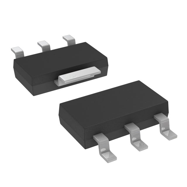
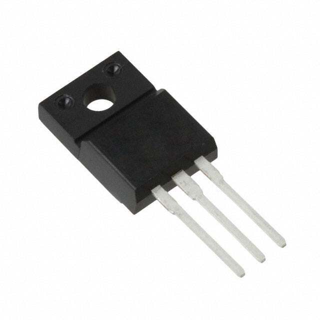
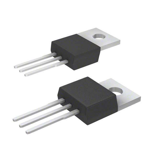
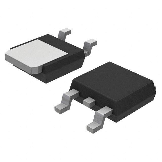
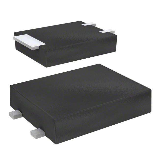
- 型号: S602TSRP
- 制造商: Littelfuse
- 库位|库存: xxxx|xxxx
- 要求:
| 数量阶梯 | 香港交货 | 国内含税 |
| +xxxx | $xxxx | ¥xxxx |
查看当月历史价格
查看今年历史价格
S602TSRP产品简介:
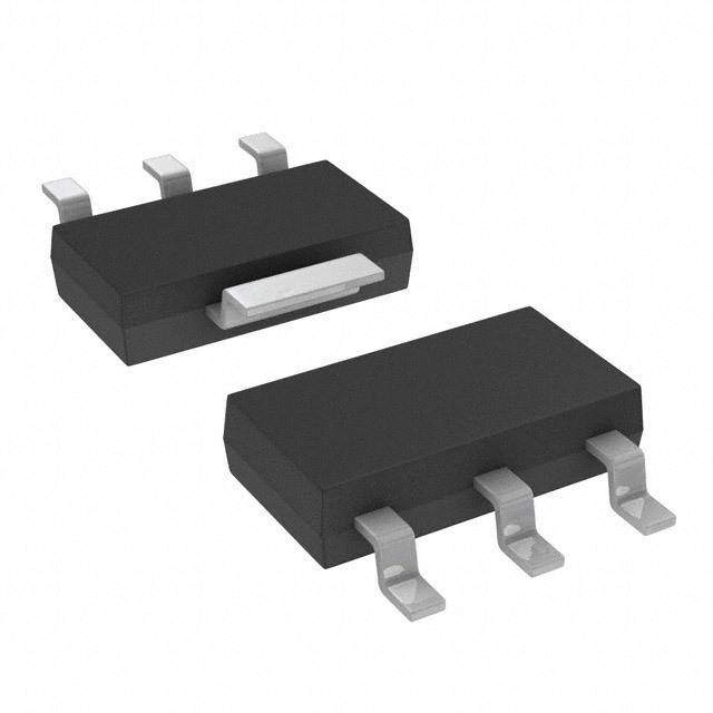
ICGOO电子元器件商城为您提供S602TSRP由Littelfuse设计生产,在icgoo商城现货销售,并且可以通过原厂、代理商等渠道进行代购。 S602TSRP价格参考¥1.92-¥1.92。LittelfuseS602TSRP封装/规格:晶闸管 - SCR, SCR 600V 1.5A Sensitive Gate Surface Mount SOT-223。您可以下载S602TSRP参考资料、Datasheet数据手册功能说明书,资料中有S602TSRP 详细功能的应用电路图电压和使用方法及教程。
Littelfuse Inc. 生产的型号为 S602TSRP 的晶闸管(SCR,Silicon Controlled Rectifier)是一种功率半导体器件,主要用于电力电子电路中实现开关和整流功能。以下是该型号的一些典型应用场景:

 1. 电机控制
   - 用于控制交流电机的速度和扭矩,例如在工业设备、家用电器(如风扇、洗衣机)中的调速功能。
   - 实现软启动功能,减少电机启动时的电流冲击。

 2. 灯光调光
   - 在照明系统中,通过相位控制调节灯的亮度,适用于白炽灯、卤素灯等传统灯具的调光器。
   - 常见于家庭或商业建筑中的灯光控制系统。

 3. 电源管理
   - 用于开关电源、不间断电源(UPS)或其他电力转换设备中,作为功率开关元件。
   - 在充电器或逆变器中,帮助实现高效的电能转换。

 4. 过压/过流保护
   - 在电路中用作保护元件,检测到异常电压或电流时快速切断电路,防止设备损坏。
   - 适用于家用电器、工业设备和汽车电子系统的保护电路。

 5. 加热控制
   - 控制电阻性加热元件的功率输出,用于电炉、烤箱、热水加热器等设备。
   - 通过脉宽调制(PWM)技术精确调节加热温度。

 6. 固态继电器(SSR)
   - 作为固态继电器的核心组件,用于替代传统机械继电器,提供更快的切换速度和更长的使用寿命。
   - 广泛应用于工业自动化、家电控制等领域。

 7. 逆变焊机
   - 在焊接设备中,用于控制焊接电流的大小和波形,确保焊接过程稳定且高效。

 性能特点
S602TSRP 是一款高可靠性、高效率的 SCR,具有以下优势:
- 额定电流为 60A,可承受较高的负载电流。
- 额定电压为 800V,适用于中高压应用场景。
- 快速开关特性,适合动态响应要求高的电路。
- 低正向压降,减少功率损耗,提高系统效率。

综上所述,S602TSRP 晶闸管广泛应用于工业、家用和汽车电子领域,能够满足多种电力控制和保护需求。
| 参数 | 数值 |
| 产品目录 | |
| 描述 | SCR SENS 600V 1.5A SOT223 T/RSCR Sen SCR 600V 1.5A 200uA |
| 产品分类 | SCR - 单个分离式半导体 |
| GateTriggerCurrent-Igt | 200 uA |
| GateTriggerVoltage-Vgt | 0.8 V |
| 品牌 | Littelfuse Inc |
| 产品手册 | |
| 产品图片 |
|
| rohs | 符合RoHS不受无铅要求限制 / 符合限制有害物质指令(RoHS)规范要求 |
| 产品系列 | 晶体闸流管,SCR,Littelfuse S602TSRP- |
| 数据手册 | |
| 产品型号 | S602TSRP |
| SCR类型 | 灵敏栅极 |
| 不重复通态电流 | 15 A |
| 产品目录页面 | |
| 产品种类 | SCR |
| 供应商器件封装 | SOT-223 |
| 保持电流Ih最大值 | 5 mA |
| 关闭状态漏泄电流(在VDRMIDRM下) | 0.005 mA |
| 其它名称 | S602TSRPCT |
| 包装 | 剪切带 (CT) |
| 商标 | Littelfuse |
| 安装类型 | 表面贴装 |
| 安装风格 | SMD/SMT |
| 封装 | Reel |
| 封装/外壳 | TO-261-4,TO-261AA |
| 封装/箱体 | SOT-223 |
| 工作温度 | -40°C ~ 125°C |
| 工厂包装数量 | 1000 |
| 开启状态RMS电流-ItRMS | 1.5 A |
| 最大工作温度 | + 125 C |
| 最大栅极峰值反向电压 | 5 V |
| 最小工作温度 | - 40 C |
| 栅极触发电压-Vgt | 0.8 V |
| 栅极触发电流-Igt | 200 uA |
| 标准包装 | 1 |
| 正向电压下降 | 1.7 V |
| 特色产品 | http://www.digikey.com/cn/zh/ph/Littelfuse/sx02xs.html |
| 电压-断态 | 600V |
| 电压-栅极触发(Vgt)(最大值) | 800mV |
| 电压-通态(Vtm)(最大值) | 1.7V |
| 电流-不重复浪涌50、60Hz(Itsm) | 12.5A,15A |
| 电流-保持(Ih)(最大值) | 5mA |
| 电流-断态(最大值) | 5µA |
| 电流-栅极触发(Igt)(最大值) | 200µA |
| 电流-通态(It(AV))(最大值) | 950mA |
| 电流-通态(It(RMS))(最大值) | 1.5A |
| 系列 | Sx02xS |
| 额定重复关闭状态电压VDRM | 600 V |




- 商务部:美国ITC正式对集成电路等产品启动337调查
- 曝三星4nm工艺存在良率问题 高通将骁龙8 Gen1或转产台积电
- 太阳诱电将投资9.5亿元在常州建新厂生产MLCC 预计2023年完工
- 英特尔发布欧洲新工厂建设计划 深化IDM 2.0 战略
- 台积电先进制程称霸业界 有大客户加持明年业绩稳了
- 达到5530亿美元!SIA预计今年全球半导体销售额将创下新高
- 英特尔拟将自动驾驶子公司Mobileye上市 估值或超500亿美元
- 三星加码芯片和SET,合并消费电子和移动部门,撤换高东真等 CEO
- 三星电子宣布重大人事变动 还合并消费电子和移动部门
- 海关总署:前11个月进口集成电路产品价值2.52万亿元 增长14.8%


PDF Datasheet 数据手册内容提取
Thyristors EV Series 1.5 Amp Sensitive SCRs Sx02xS EV Series RoHS Description This new 1.5A sensitive gate SCR component series offers high static dv/dt and low turn-off time (t) through its small q die planar construction design. All SCR junctions are glass- passivated to ensure long term reliability and parametric stability. Features • Surge • Sensitive gate for direct capability > 15Amps microprocessor interface • Blocking voltage • Thru hole and surface (V / V ) mount packages DRM RRM capability — up to 600V • RoHS compliant and Main Features • High dv/dt noise immunity Halogen-Free Symbol Value Unit • Improved turn-off time (tq) < 35 μsec. I 1.5 A T(RMS) V /V 400 or 600 V DRM RRM Schematic Symbol I 200 µA GT A Applications The Sx02xS EV series is specifically designed for solenoid drive often seen in GFCI and similar safety cut-off devices. G K Absolute Maximum Ratings Symbol Parameter Value Unit TO-92 T = 65°C C RMS on-state current I SOT-89 T = 80°C 1.5 A T(RMS) (full sine wave) C SOT-223 T = 95°C C TO-92 T = 65°C C I Average on-state current SOT-89 T = 80°C 0.95 A T(AV) C SOT-223 T = 95°C C TO-92 F = 50 Hz 12.5 Non repetitive surge peak on-state current I SOT-89 A TSM (Single cycle, T initial = 25°C) J SOT-223 F = 60 Hz 15.0 t = 10 ms F = 50 Hz 0.78 p I2t I2t Value for fusing A2s t = 8.3 ms F = 60 Hz 0.93 p TO-92 di/dt Critical rate of rise of on-state current IG = 10mA SOT-89 T = 125°C 50 A/μs J SOT-223 I Peak gate current t = 10 μs T = 125°C 1.0 A GM p J P Average gate power dissipation T = 125°C 0.1 W G(AV) J T Storage junction temperature range -40 to 150 °C stg T Operating junction temperature range -40 to 125 °C J © 2018 Littelfuse, Inc. Specifications are subject to change without notice. Revised: 12/11/18
Thyristors EV Series 1.5 Amp Sensitive SCRs Electrical Characteristics (T = 25°C, unless otherwise specified) J Sx02xS Sx02xS1 Symbol Description Test Conditions Unit Min Max Min Max I DC Gate Trigger Current V = 12V; R = 60 Ω 15 200 15 100 µA GT D L V DC Gate Trigger Voltage V = 12V; R = 60 Ω — 0.8 — 0.8 V GT D L V Peak Reverse Gate Voltage I = 10μA 5 — 5 — V GRM RG I Holding Current R = 1 kΩ — 5 — 3 mA H GK T = 125°C J Critical Rate-of-Rise of V = V / V (dv/dt)s D DRM RRM 25 — 25 — V/μs Off-State Voltage Exponential Waveform R = 1 kΩ GK T = 125°C @ 600 V t Turn-Off Time J — 35 — 35 μs q R = 1 kΩ GK I = 10mA G t Turn-On Time PW = 15μsec — 3 — 3 μs gt I = 3.0A (pk) T VD=VDRM, TJ=125°C, V Gate Non-Trigger Voltage 0.2 - 0.2 - V GD RL=3.3KΩ x0 = voltage/10 Static Characteristics (T = 25°C, unless otherwise specified) J Value Symbol Description Test Conditions Unit Min Max V Peak On-State Voltage I = 3.0A (pk) — 1.70 V TM TM T = 25°C @ V = V J D DRM — 5 μA R = 1 kΩ I Off-State Current, Peak Repetitive GK DRM T = 125°C @ V = V J D DRM — 500 μA R = 1 kΩ GK Thermal Resistances Symbol Parameter Value Unit TO-92 50 R Junction to case (AC) I = 1.5A 1 SOT-89 35 °C/W θ(J-C) T (RMS) SOT-223 25 TO-92 160 R Junction to ambient I = 1.5A 1 SOT-89 90 °C/W θ(J-A) T (RMS) SOT-223 60 1 60Hz AC resistive load condition, 100% conduction. Additional Information Datasheet Resources Samples © 2018 Littelfuse, Inc. Specifications are subject to change without notice. Revised: 12/11/18
Thyristors EV Series 1.5 Amp Sensitive SCRs Figure 1: Normalized DC Gate Trigger Current Figure 2: Normalized DC Holding Current vs. Junction Temperature vs. Junction Temperature 2.5 2.0 ormalized Gate: Trigger Current @ T / I@ 25ºCIGTjGT0112....0550 Normalized Holding Current(I@ T / I @25∞C)H JH011...505 N 0.0 0.0 -40 -25 -10 +5 +20 +35 +50 +65 +80 +95 +110 +125 -40 -25 -10 +5 +20 +35 +50 +65 +80 +95 +110 +125 Junction Temperature (T) °C Junction Temperature (T) °C J J Figure 3: Normalized DC Gate Trigger Voltage Figure 4: On-State Current vs. On-State vs. Junction Temperature Voltage (Typical) 10 1.5 s p m A – malized Gate: Trigger Voltage (V @ T / V @ 25ºC)GTjGT1.0 aneous On-state Current (I) T 2468 Nor 0.5 stant n I 0 -40 -25 -10 +5 +20 +35 +50 +65 +80 +95 +110 +125 0.8 1.0 1.2 1.4 1.6 1.8 2.0 2.2 Junction Temperature (T) °C J Instantaneous On-state Voltage (V) –Volts T Figure 5: Power Dissipation (Typical) Figure 6: Maximum Allowable Case Temperature vs. RMS On-State Current vs. On-State Current 1.5 s) 130 u pation, P (Watts)D1.0 CLCOUOARNDRD:EU RNCeTTs WiIsOtANivV eAE NoFOrG IRLnMEd:u :1 cS8tii0nvouesoidal mperature, T (CelsiC111021000 TO-92 SOT-223 er Dissi Case Te 8900 erage Pow 0.5 Allowable 6700 CCLCOAUOASRNDERD :TEU RENCeMTTs WPiIsOEtANiRvVA eAET NoFUOrG RIRLnEMEd: :uM :1 cS8etii0anvosueusroeidd aals SOT-89 Av ax shown on dimensional drawings M 50 0.0 0.0 0.5 1.0 1.5 0.0 0.5 1.0 1.5 RMS On-state Current [I ] (Amps) RMS On-state Current [I ] (Amps) T(RMS) T (RMS) © 2018 Littelfuse, Inc. Specifications are subject to change without notice. Revised: 12/11/18
Thyristors EV Series 1.5 Amp Sensitive SCRs Figure 7: Typical DC Gate Trigger Current with R vs. Figure 8: Typical DC Holding Current with R vs. GK GK Figure 7: JTyupnicctaiol nD TCe Gmapteer Tartiugrgee rfo Cru Srxre0n2tx wSith R vs. Figure 8: JTyupnicctaiol nD TCe Hmopledrinatgu Creu frorern Stx w02itxhS R vs. GK GK Junction Temperature for Sx02xS Junction Temperature for Sx02xS 100 100 100 100 R =10Ω GK R =10Ω mA) 1100 RRGK==110000ΩΩ RGK=10Ω mA) RR=GGKK1=0100ΩΩ Trigger Current I (Trigger Current I (mA)GTGT 00.00..11111 GK RRRGRGKKGG==KK=4=417N17NK0K0ooΩΩΩΩ RRGGKK Holding Current I (Holding Current I (mA)HH 111010 RRGRGRKRKGG=GKGKNK=1K===40o411707 KRK0Ω0ΩGΩΩΩK 0.01 No R GK 0.001 0.1 0.001-40 -15 10 35 60 85 110 135 0.1-40 -15 10 35 60 85 110 135 -40 -15Junc1ti0on Tem35peratu6r0e (TJ) 8-5-(°C)110 135 -40 -15 Junc1t0ion Te3m5peratu60re (TJ) 8--5(°C)110 135 Junction Temperature (TJ) --(°C) Junction Temperature (TJ) --(°C) Figure 9: Typical Static dv/dt with R vs. Junction Figure 10: Typical turn off time with R vs. Junction GK GK Figure 9: T Teympipcaelr aSttuarteic f odrv /Sdxt0 w2xitSh R vs. Junction Figure 10: T Teympipcaelr atuturnre o ffof rt iSmxe0 2wxiSth R vs. Junction GK GK Temperature for Sx02xS Temperature for Sx02xS 10000 32 10000 R =10Ω 2382 RGK=1KΩ RGGKK=10Ω 2248 RGK=1KΩ Static dv/dt (V/μs)Static dv/dt (V/μs)11010100000000 RRRRRRGGGGGKGKKK=K=K====4422117722KK0000ΩΩΩΩΩΩ Turn off time Tq (µs)Turn off time Tq (µs) 11211222604826048 RRRRGRRGKGGKGG==KKKK==1==1410410070070Ω0ΩΩ0ΩΩΩ 4 0 10 -40 -15 10 35 60 85 110 135 25 45 65 85 105 125 0 10 -40 -15 10 35 60 85 110 135 25 4J5unction T6e5mperature8 5(TJ) --(°C1)05 125 Junction Temperature (TJ) --(°C) Junction Temperature (TJ) --(°C) Junction Temperature (TJ) --(°C) Figure 11: Surge Peak On-State Current vs. Number of Cycles 20 Supply Frequency: 60Hz Sinusoidal Load: Resistive e 15 RMS On-State Current [I ]: Max Rated Value at Stat 12 Specific Case TemperaturTe(RMS) ve) On-mps.17890 N1fo. olGltoeawste:in cgo snutrrogle m cuayrr ebnet loinstte drvuarli.ng and immediately urge (Non-repetiti) – ACurrent (ITSM 3564 1.5 A Components 2te. mOpveerralotaudre m haays nreottu brnee rde ptoe astteeda duyn-tsitl ajuten crtaitoend value. k S 2 a e P 1 1 2 3 4 5 678910 20 30 40 60 80100 200 300400600 1000 Surge Current Duration – Full Cycle © 2018 Littelfuse, Inc. Specifications are subject to change without notice. Revised: 12/11/18
Thyristors EV Series 1.5 Amp Sensitive SCRs Soldering Parameters Reflow Condition Pb – Free assembly t P T P - Temperature Min (Ts(min)) 150°C e RRaammpp--uupp Pre Heat -- TTeimmep e(mraitnu rteo Mmaaxx )( T(ts()max)) 2600 0–° C180 secs rutare TS(mTaxL) tL s p m RRaammpp--ddoown Average ramp up rate (Liquidus Temp) PPrreehheeaatt (TL) to peak 5°C/second max eT TS(min) t T to T - Ramp-up Rate 5°C/second max S S(max) L - Temperature (T) (Liquidus) 217°C Reflow L 25 - Time (min to max) (ts) 60 – 150 seconds time to peak temperature Time Peak Temperature (T) 260+0/-5 °C P Time within 5°C of actual peak 20 – 40 seconds Temperature (t) p Ramp-down Rate 5°C/second max Time 25°C to peak Temperature (T) 8 minutes Max. P Do not exceed 280°C Physical Specifications Environmental Specifications Test Specifications and Conditions Terminal Finish 100% Matte Tin-plated. MIL-STD-750, M-1040, Cond A Applied AC Blocking Peak AC voltage @ 125°C for 1008 hours UL Recognized compound meeting Body Material flammability rating V-0 MIL-STD-750, M-1051, Temperature Cycling 100 cycles; -40°C to +150°C; 15-min dwell-time Lead Material Copper Alloy EIA / JEDEC, JESD22-A101 Temperature/ 1008 hours; 160V - DC: 85°C; 85% Humidity rel humidity Design Considerations MIL-STD-750, M-1031, High Temp Storage 1008 hours; 150°C Careful selection of the correct component for the Low-Temp Storage 1008 hours; -40°C application’s operating parameters and environment will go a long way toward extending the operating life of the Resistance to MIL-STD-750 Method 2031 Thyristor. Good design practice should limit the maximum Solder Heat continuous current through the main terminals to 75% of Solderability ANSI/J-STD-002, category 3, Test A the component rating. Other ways to ensure long life for a power discrete semiconductor are proper heat sinking Lead Bend MIL-STD-750, M-2036 Cond E and selection of voltage ratings for worst case conditions. Overheating, overvoltage (including dv/dt), and surge currents are the main killers of semiconductors. Correct mounting, soldering, and forming of the leads also help protect against component damage. © 2018 Littelfuse, Inc. Specifications are subject to change without notice. Revised: 12/11/18
Thyristors EV Series 1.5 Amp Sensitive SCRs Dimensions — TO-92 (E Package) A Inches Millimeters TC MEASURING POINT Dimensions Min Max Min Max B A 0.175 0.205 4.450 5.200 B 0.170 0.210 4.320 5.330 SEATING C 0.500 — 12.700 — PLANE D 0.135 — 3.430 — C GATE E 0.125 0.165 3.180 4.190 F 0.080 0.105 2.040 2.660 G 0.016 0.021 0.407 0.533 G ANODE H H 0.045 0.055 1.150 Anode 1.390 CATHODE I I 0.095 0.105 2.420 2.660 D J 0.015 0.020 0.380 0.500 E J F F Anode Gate Cathode Dimensions – SOT-223 Anode Anode Anode Gate Cathode Anode Gate Cathode Anode Gate Cathode Inches Millimeters Anode Dimensions Min Typ Max Min Typ Max Pad Layout for SOT-223 A 0.248 0.256 0.264 6.30 6.50 6.70 B 0.130 0.138 0.146 3.30 3.50 3.70 3.3 (0.130”) C — — 0.071 — — 1.80 1.5 D 0.001 — 0.004 0.02 — 0.10 (0.059”) E 0.114 0.118 0.124 2.90 3.00 3.15 (0.01.427”) (0.029.31”) (0.62.542”) F 0.024 0.027 0.034 0.60 0.70 0.85 (3x) 1.5 G — 0.090 — — 2.30 — (0.059”) 4.6 H — 0.181 — — 4.60 — (0.181”) I 0.264 0.276 0.287 6.70 7.00 7.30 Dimensions in Millimeters (Inches) J 0.009 0.010 0.014 0.24 0.26 0.35 Recommended Soldering Footprint for SOT223 K 10° MAX © 2018 Littelfuse, Inc. Specifications are subject to change without notice. Revised: 12/11/18
A Tc Measuring Point Anode J Thyristors EV Series 1.5 Amp Sensitive SCRs A Tc Measuring Point J BAnode D E B D F Cathode Gate Dimensions – SOT-89 G Anode A Tc Measuring PEoint J Anode A Tc Measuring Point C Anode F Cathode J Gate H G B Anode D B C D E H F Cathode E Gate G Anode c F Cathode Inches Millimeters Gate G C Dimension Anode H Min Typ Max Min Tgyp Max A 0.173 — 0.181 4.40 — 4.60 C Pad Layout for SOT-89 c H B 0.090 — 0.102 2.29 — 2.60 (2.21) a .087 C 0.05g5 — 0.063 1.40 —f 1.60 d (1.12) .044 D 0.155 — 0.167 3.94 — 4.25 c e E 0.035 — 0.047 0.89 — 1.20 (3.1.5941) g a F 0.056 f — d0.062 1.42 — 1.57 (1.19) c b .047 G 0.115 — 0.121 2.92 — 3.07 (0.91) g a .036 f d H e0.014 — 0.017 0.35 — 0.44 (1.63) (1.63) .064 .064 Dimensions in Millimeters (Inches) I 0.014 — 0.019 0.36 — 0.48 ae b f d J 0.064 — 0.072 1.62 — 1.83 b e b Product Selector Voltage Part Number Gate Sensitivity Package 400V 600V S402ES X -- 200µA TO-92 S602ES -- X 200µA TO-92 S402TS X -- 200µA SOT-223 S602TS -- X 200µA SOT-223 Sx02ES1 X X 100µA TO-92 Sx02BS1 X X 100µA SOT-89 Sx02BS X X 200µA SOT-89 Sx02TS1 X X 100µA SOT-223 Note: x = voltage/100 © 2018 Littelfuse, Inc. Specifications are subject to change without notice. Revised: 12/11/18
Thyristors EV Series 1.5 Amp Sensitive SCRs Packing Options Part Number Marking Weight Packing Mode Base Quantity Sx02ES Sx02ES 0.217 g Bulk 2500 Sx02ESAP Sx02ES 0.217 g Ammo Pack 2000 Sx02ESRP Sx02ES 0.217 g Tape & Reel 2000 Sx02TSRP Sx02TS 0.120 g Tape & Reel 1000 Sx02ES1 Sx02ES 0.217 g Bulk 2500 Sx02ES1AP Sx02ES1 0.217 g Ammo Pack 2000 Sx02ES1RP Sx02ES1 0.217 g Tape & Reel 2000 Sx02TS1RP Sx02TS1 0.120 g Tape & Reel 1000 Sx02BSRP Sx02BS 0.053 g Tape & Reel 1000 Sx02BS1RP Sx02BS1 0.053 g Tape & Reel 1000 TO-92 (3-lead) Reel Pack (RP) Radial Leaded Specifications Meets all EIA-468-C Standards 0.236 0.02 (0.5) 0.098 (2.5) MAX 1.6 (6.0) 1.26 (41.0) (32.0) 0.708 (18.0) 0.354 (9.0) (102.5.7) 0.1 (2.54) Cathode Anode 0.2 (5.08) Gate 14.17(360.0) 0 (.41.507)DIA Flat up 1.97 (50.0) Dimensions are in inches Direction of Feed (and millimeters). © 2018 Littelfuse, Inc. Specifications are subject to change without notice. Revised: 12/11/18
Thyristors EV Series 1.5 Amp Sensitive SCRs TO-92 (3-lead) Ammo Pack (AP) Radial Leaded Specifications Meets all EIA-468-C Standards 0(.62.306) 0.02 (0.5) 0.098 (2.5) MAX 1.27 1.62 (32.2) (41.2) 0.708 (18.0) 0.354 (9.0) (102.5.7) 0.1 (2.54) 0.2 (A5n.0o8d)e GateCathode 0(4.1.05)7DIA Flat down Directionof Feed 25 Devices per fold 1.85 (47.0) 12.2 (310.0) Dimensions are in inches 1.85 (and millimeters). (47.0) 13.3 (338.0) SOT-223 Reel Pack (RP) Specifications 1.5 mm 4 mm 8 mm 2 mm A 1.75 mm 5.5 mm 12 mm K A GATE 180 mm 13 mm Abor Hole Diameter 13.4 mm © 2018 Littelfuse, Inc. Specifications are subject to change without notice. Revised: 12/11/18
Thyristors EV Series 1.5 Amp Sensitive SCRs Part Numbering System Part Marking System Sx02xxxxx SCR SERIES PACKING TYPE Blank: Bulk RP: Reel Pack (TO-92) VOLTAGE : Embossed Carrier Pack 4: 400V (SOT-223) SOT89 SOT223 6: 600V AP: Ammo Pack (TO-92) CURRENT SENSITIVITY 02: 1.5A S: 200µA Sensitive SCR Line1 = Littelfuse Part Number S1: 100µA Sensitive SCR Line2 = continuation…Littelfuse Part Number Y = Last Digit of Calendar Year PACKAGE TYPE M = Letter Month Code (A-L for Jan-Dec) E: TO-92 L = Location Code T: SOT-223 DD = Calendar Date B: SOT-89 TO-92 Disclaimer Notice - Information furnished is believed to be accurate and reliable. However, users should independently evaluate the suitability of and test each product selected for their own applications. Littelfuse products are not designed for, and may not be used in, all applications. Read complete Disclaimer Notice at www.littelfuse.com/disclaimer-electronics. © 2018 Littelfuse, Inc. Specifications are subject to change without notice. Revised: 12/11/18
 Datasheet下载
