ICGOO在线商城 > RTY060HVNAX
- 型号: RTY060HVNAX
- 制造商: Honeywell Solid State Electronics
- 库位|库存: xxxx|xxxx
- 要求:
| 数量阶梯 | 香港交货 | 国内含税 |
| +xxxx | $xxxx | ¥xxxx |
查看当月历史价格
查看今年历史价格
RTY060HVNAX产品简介:
ICGOO电子元器件商城为您提供RTY060HVNAX由Honeywell Solid State Electronics设计生产,在icgoo商城现货销售,并且可以通过原厂、代理商等渠道进行代购。 提供RTY060HVNAX价格参考以及Honeywell Solid State ElectronicsRTY060HVNAX封装/规格参数等产品信息。 你可以下载RTY060HVNAX参考资料、Datasheet数据手册功能说明书, 资料中有RTY060HVNAX详细功能的应用电路图电压和使用方法及教程。
| 参数 | 数值 |
| 产品目录 | |
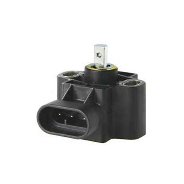
| 描述 | SENSOR HALL EFFECT ROTARY工业移动感应器和位置传感器 60 deg (+/- 30 deg) 10-30V NA Pinout |
| 产品分类 | |
| 品牌 | Honeywell |
| 产品手册 | |
| 产品图片 |
|
| rohs | 符合RoHS无铅 / 符合限制有害物质指令(RoHS)规范要求 |
| 产品系列 | 工业移动感应器和位置传感器,Honeywell RTY060HVNAXRTY |
| mouser_ship_limit | 该产品可能需要其他文档才能发货到中国。 |
| 数据手册 | http://sensing.honeywell.com/index.php?ci_id=147803点击此处下载产品Datasheet点击此处下载产品Datasheet点击此处下载产品Datasheet |
| 产品型号 | RTY060HVNAX |
| 产品培训模块 | http://www.digikey.cn/PTM/IndividualPTM.page?site=cn&lang=zhs&ptm=25859 |
| 产品种类 | 工业移动感应器和位置传感器 |
| 其它名称 | 480-3864 |
| 准确性 | +/- 1.6 % |
| 商标 | Honeywell |
| 安装类型 | 底座安装 |
| 容差 | 1.6 % |
| 封装 | Bulk |
| 工作温度 | -40°C ~ 125°C |
| 总电阻 | 10 kOhms |
| 技术 | 霍尔效应 |
| 旋转角度 | 60° (±30°) |
| 最大工作温度 | + 125 C |
| 机械行程 | 60 deg |
| 标准包装 | 1 |
| 温度范围 | - 40 C to + 125 C |
| 用于测量 | 旋转位置 |
| 电压-电源 | 10 V ~ 30 V |
| 电压额定值 | 10 VDC to 30 VDC |
| 电阻(Ω) | - |
| 电阻容差 | - |
| 端子类型 | 连接器 |
| 类型 | Hall-Effect Rotary Position Sensors |
| 系列 | RTY |
| 线性 | 1 % |
| 线性度 | ±1% |
| 线性范围 | - |
| 致动器类型 | 轴 |
| 输出类型 | Analog - Voltage |



- 商务部:美国ITC正式对集成电路等产品启动337调查
- 曝三星4nm工艺存在良率问题 高通将骁龙8 Gen1或转产台积电
- 太阳诱电将投资9.5亿元在常州建新厂生产MLCC 预计2023年完工
- 英特尔发布欧洲新工厂建设计划 深化IDM 2.0 战略
- 台积电先进制程称霸业界 有大客户加持明年业绩稳了
- 达到5530亿美元!SIA预计今年全球半导体销售额将创下新高
- 英特尔拟将自动驾驶子公司Mobileye上市 估值或超500亿美元
- 三星加码芯片和SET,合并消费电子和移动部门,撤换高东真等 CEO
- 三星电子宣布重大人事变动 还合并消费电子和移动部门
- 海关总署:前11个月进口集成电路产品价值2.52万亿元 增长14.8%

PDF Datasheet 数据手册内容提取
Hall-effect Rotary Position Sensors RTY Series with Integral Actuator RTP Series with External Actuator Datasheet
RTY Series and RTP Series Hall-effect Rotary Position Sensors The RTY Series and RTP Series Hall-effect Rotary Position Sensors provide non-contact sensing in harsh transportation and industrial applications at a competitive cost. • RTY Series: These shaft activated products are available in two versions: an integral shaft with or without a lever. The lever may allow customers to reduce the number of mechanical linkages required for their applications, which may reduce the cost of the overall customer solution. • RTP Series: Takes non-contact sensing to the next level by separating the magnet from the sensor body. The absence of the actuator shaft removes the wear and tear on the bearings caused by radial forces. A choice of a bare or a housed magnet is available. These products use a magnetically biased, Hall-effect integrated circuit (IC) to sense rotary movement of the actuator over a set operating range. Rotation of the actuator changes the magnet’s position relative to the IC. The resulting flux density change is converted to a linear output. The IC, together with conditioning and protection circuitry, is sealed in an IP69K-qualified rugged package for durability in most harsh environments. Eight operating ranges from 50° to 360° are tolerant to over-travel and allow use in most common applications. Low voltage and high voltage versions cover an input voltage range of 4.5 Vdc to 30 Vdc. Honeywell’s industry-leading capabilities in research and development provide the customer with known quality and support. Features Potential Applications • True, non-contact operation TRANSPORTATION • 35 M cycle product life (RTY Series); unlimited rotation (RTP • Position and movement detection (pedals, throttles, Series) gear shift, levers, steering, linkages, and hitches) in • Solid-state Hall-effect technology trucks, buses, off-road vehicles, cranes, and industrial/ • Rugged IP69K-sealed package with integral connector construction/agricultural vehicles and equipment) • Automotive-grade EMI/EMC testing, integrated reverse • Suspension/kneeling position (buses, trucks) polarity, and short circuit protection • Tilt/trim position (boat engines, tilling equipment) • Industry-standard AMP termination, 32 mm mounting pitch, INDUSTRIAL North American or European pinout styles, and compact package • Valve control • Eight operating ranges up to 360° • HVAC damper control • Irrigation equipment pivot control RUGGED • LONG PRODUCT LIFE • NON-CONTACT SENSING 2 sensing.honeywell.com
Hall-effect Rotary Position Sensors Table 1. Electrical Specifications RTY Series RTP Series Characteristic LV (Low Voltage) HV (High Voltage) LV (Low Voltage) HV (High Voltage) Supply voltage 5 ±0.5 Vdc 10 Vdc to 30 Vdc 5 ±0.5 Vdc 10 Vdc to 30 Vdc Supply current: normal 20 mA max. 32 mA max. 20 mA max. 32 mA max. during output to ground short 25 mA max. 47 mA max. 25 mA max. 47 mA max. Output: standard 0.5 Vdc to 4.5 Vdc 0.5 Vdc to 4.5 Vdc 0.5 Vdc to 4.5 Vdc 0.5 Vdc to 4.5 Vdc ratiometric non-ratiometric ratiometric non-ratiometric inverted 4.5 Vdc to 0.5 Vdc 4.5 Vdc to 0.5 Vdc 4.5 Vdc to 0.5 Vdc 4.5 Vdc to 0.5 Vdc ratiometric non-ratiometric ratiometric non-ratiometric Output signal delay 4 ms typ. Overvoltage protection 10 Vdc — 10 Vdc — Reverse polarity protection -10 Vdc -30 Vdc -10 Vdc -30 Vdc Output to ground short circuit continuous protection Resolution 12 bit Output load resistance 10 kOhm typ. (pull down to ground) EMI: 100 V/m per ISO11452-2 from 200 MHz to 1000 MHz 100 V/m per ISO11452-2 from 200 MHz to 1000 MHz radiated immunity conducted immunity 100 mA BCI per ISO11452-4 100 mA BCI per ISO11452-4 100 mA BCI per ISO11452-4 100 mA BCI per ISO11452-4 from 1 MHz to 200 MHz from 1 MHz to 400 MHz from 1 MHz to 200 MHz from 1 MHz to 400 MHz EMC exceeds CE requirements Table 2. Mechanical Specifications RTY Series RTP Series Characteristic LV (Low Voltage) HV (High Voltage) LV (Low Voltage) HV (High Voltage) Expected life 35 M cycles infinite rotation Air gap: - bare magnet actuator — 3,00 mm ±0.5 mm [0.12 in ±0.02 in] housed magnet actuator — 2,00 mm ±0.5 mm [0.08 in ±0.02 in] misalignment — 2.002,00 mm [0.08 in] max. Material: shaft stainless steel — magnet — NdFeB sensor housing PBT plastic PBT plastic housed magnet overmold — PPS plastic sensor/housed magnet bushing — brass sensor bushing stainless steel — Mating connector AMP Superseal 282087-1 Mechanical end stop no Mounting screw sizes: sensor to mounting surface non-magnetic, stainless steel M5 screws and non-magnetic, stainless steel M4 X 0.7 screws and 10 mm [0.39 in] OD washers 8 mm [0.31 in] OD washers lever to mounting surface non-magnetic stainless steel M6 screws, — housed magnet actuator to — non-magnetic, stainless steel M3 X 0.5 actuator mounting shaft plain cup point set screws Approvals CE sensing.honeywell.com 3
RTY Series and RTP Series Table 3. Environmental Specifications RTY Series RTP Series Characteristic LV (Low Voltage) HV (High Voltage) LV (Low Voltage) HV (High Voltage) Operating temperature range -40 °C to 125 °C [-40 °F to 257 °F] Ingress protection IP69K Media compatibility heavy transportation fluids Shock1 50 G peak Vibration1 20 G peak concentration 5% ±1% for 240 hr per SAE J1455 bare magnet: 96 hr for as per ASTM B117 Salt fog Section 4.3.3.1 (at 5.0 Vdc, 38 °C [100 F °]) housed magnet: 240 hr per ASTM B117 1 Does not apply RTY Series sensor shaft with lever. CAUTION NOTICE ELECTROSTATIC SENSITIVE Ferrous material or magnet material more DEVICES DO NOT OPEN OR HANDLE than 300 Gauss within 10 mm [0.39 in] EXCEPT AT A STATIC FREE WORKSTATION from sensor boundary may impact ESD SENSITIVITY: CLASS 2 sensor performance. Figure 1. All Available Configurations Series Actuator Type Series Actuator Type Integral shaft without lever Separate bare magnet RTY RTP Integral shaft with lever Separate housed magnet 4 sensing.honeywell.com
Hall-effect Rotary Position Sensors RTFigYu reS 2e. Priroedsu cHt Naolml-eEncflfaetucret Rotary Position Sensors PrRoTdY uSecrite sNomenclature For example, RTY050LVEAA defines an RTY Series Hall-Effect Rotary Position Sensor, 50° (±25°) sensing range angle, 5 Vdc supply voltage, European pinout style, 4.5 Vdc (left), 0.5 Vdc (right) output type, shaft without lever actuation type RTY 050 LV E A A Sensing Range Series Supply Voltage Pinout Style Output Type Actuator Type Angle RTY Series Hall-Effect Rotary Postion Sensor 050 50° (±25°) LV 5 Vdc E European: A Standard: X Shaft without lever with Integral Actuator pin 1 = GND 0.5 Vdc (left), 4.5 Vdc (right) 060 60° (±30°) HV10 Vdc to 30 Vdc pin 2 = Vcc pin 3 = output B Inverted: 4.5 Vdc (left), 0.5 Vdc (right) 070 70° (±35°) NNorth American: pin 1 = Vcc 090 90° (±45°) pin 2 = GND A Shaft with lever pin 3 = output 120 120° (±60°) 180 180° (±90°) 270 270° (±135°) 360 360° (±180°) 005965-2-EN XX 2015 Copyright © 2015 Honeywell International Inc. All Rights Reserved. RTP Series Hall-Effect Rotary Position Sensors Product Nomenclature RTP Series For example, RTP050LVEBX defines an RTP Series Hall-Effect Rotary Position Sensor, 50° (±25°) sensing range angle, 5 Vdc supply voltage, European pinout style, inverted 4.5 Vdc (left), 0.5 Vdc (right) output type, bare magnet actuator type RTP 050 LV E B X Sensing Range Series Supply Voltage Pinout Style Output Type Actuator Type Angle RTP Series Hall-Effect Rotary Postion Sensor 050 50° (±25°) LV 5 Vdc E European: A Standard: X Bare magnet with External Actuator pin 1 = GND 0.5 Vdc (left), 4.5 Vdc (right) 060 60° (±30°) HV10 Vdc to 30 Vdc pin 2 = Vcc pin 3 = output B Inverted: 4.5 Vdc (left), 0.5 Vdc (right) 070 70° (±35°) N North American: pin 1 = Vcc 090 90° (±45°) pin 2 = GND A Housed magnet pin 3 = output (carrier type “A”)2 120 120° (±60°) 180 180° (±90°) 270 270° (±135°) 350 350° (±175°) 1 360° Sensing Range Angle available upon request. 2 Customized housed magnet actuators available upon request. 360 360° (±180°)1 005976-1-EN May 2015 Copyright © 2015 Honeywell International Inc. All Rights Reserved. sensing.honeywell.com 5
RTY Series and RTP Series Figure 3. RTY Series Mounting Dimensions (For reference only: mm [in.]) Sensor without lever Output diagram 22,0 5,3 [0.87] [0.21] ø5,35 8,3 [0.21] [0.33] 37.0 ø15,50 [1.46] [0.61] 55 [2.17] 4,60 36,4 [0.18] [1.43] 1 3 2 1 Mounting surface 9,5 [0.37] 26,0 13,8 [1.02] [0.54] 15,6 B [0.61] θ 1 Non-magnetic, stainless steel M5 A C screws and 10 mm [0.39 in] OD ø6,00 −θ/2° +θ/2° washers, mounting torque is 1 [0.24] 2,5 ±0,5 N m [22.1 ±4.4 in-lb] 2 3 4,12 [0.16] 25 [0.98] Sensor with lever 8,3 40,0 [0.33] 22,0 5,00 [1.57] [0.87] [0.20] 10,0 15,0 Standard Output ø5,35 [0.39] [0.59] [0.21] A = Left output: 0.5 Vdc B = Zero reference 11 37,0 22,0 C = Right output: 4.5 Vdc [1.46] [0.87] Inverted Output 55 [2.17] 2 A = Left output: 4.5 Vdc [31.64,34] 11 Mounting B = Zero reference surface C = Right output: 0.5 Vdc 9,5 [0.37] 26,0 13,8 [1.02] [0.54] 15,7 [0.62] 14,0 1 Non-magnetic, stainless steel M5 [0.55] screws and 10 mm [0.39 in] OD washers, mounting torque is 2,5 ± 0,5 N m [22.1 ±4.4 in-lb] 2 Non-magnetic stainless steel M6 screws, mounting torque is 8 N m [70.8 in-lb] max. 6 sensing.honeywell.com
Hall-effect Rotary Position Sensors Figure 4. RTP Series Mounting Dimensions (For reference only: mm [in].) Sensor with bare magnet actuator Output diagram B 3,00 ±0,5 Air gap 43,3 θ [0.12 ±0.02] [1.70] 5,00 [0.20] 32,00 ±0,15 A −θ/2° +θ/2° C 10,80 [1.26 ±0.01] ø5,00 [0.43] [0.20] 18,5 [0.73] ø12,00 [0.47] Ssuernfascineg [526.2,94] 2 X ø [04.,1370± ±00.0,52] 1 17,8 16,00 [0.70] [0.63] Standard Output Mounting A = Left output: 0.5 Vdc Bare surface 11,00 magnet B = Zero reference actuator Bare Magnet [0.43] C = Right output: 4.5 Vdc Inverted Output 1 Non-magnetic, stainless steel M4 X 0.7 screws and A = Left output: 4.5 Vdc 8 mm [0.39 in] OD washers, torque is 2,0 ±0,2 N m B = Zero reference [17.7 ±1.8 in-lb]. C = Right output: 0.5 Vdc Orientation hole Sensor with housed magnet actuator Output Diagram B 43,3 2,00 ±0,5 Air gap [1.70] θ Sensing [0.08 ±0.02] 32,00 ±0,15 A C surface 10,80 [1.26 ±0.01] −θ/2° +θ/2° [0.43] 4,50 [0.18] ø8,00 18,5 [0.31] [0.73] 2X M3 X 0.5 2X ø4,30 ±0,5 56,9 [0.17±0.02] 1 14,0 [2.24] [0.55] 2 16,0 ±0,5 [0.63 ±0.02] 17,8 6,0 [0.70] [0.24] 16,00 [0.63] Standard Output Mounting Housed A = Left output: 0.5 Vdc Housed Magnet surface macatuganteotr B = Zero reference ø15,00 [0.59] C = Right output: 4.5 Vdc Inverted Output 1 Non-magnetic, stainless steel M3 X 0.5 plain cup point set A = Left output: 4.5 Vdc screws, torque is 0,5 N m to 0,6 N m [4.42 in-lb to 5.31 in-lb] 2 Non-magnetic, stainless steel M4 X 0.7 screws and B = Zero reference Orientation 8 mm [0.31 in] OD washers, torque is 2,0 ±0,2 N m C = Right output: 0.5 Vdc arrow [17.7 ±1.8 in-lb]. sensing.honeywell.com 7
RTY Series and RTP Series Table 4 RTY Series Functional Characteristics1 Characteristic Sensing Linearity Accuracy Standard Output Inverted Output Angle Error2 Error3 50° (±25°) Clamp High Clamp High 4.5 4.5 c) c) 60° (±35°) d d V V ( ( e e g g a a t2.5 t2.5 70° (±35°) ol ol V V ut ut p p ut ut 90° (±45°) O O Clam p L00o..w05 Clam p L00o..w05 A B C A B C 120° (±60°) -25 0 +25 -25 0 +25 -30 0 +30 -30 0 +30 -35 0 +35 -35 0 +35 180° (±90°) -45 0 +45 -45 0 +45 -60 0 +60 -60 0 +60 -90 0 +90 -90 0 +90 -135 0 +135 -135 0 +135 270° (±135°) Actuator Position (°) Actuator Position (°) ±1.0% ±1.6% 4.5 4.5 c) c) d d V V e ( e ( g g a2.5 a2.5 olt olt V V 360° (±180°) ut ut p p ut ut O O 00..50 00..50 A B C A B C -180 0 +180 -180 0 +180 Actuator Position (°) Actuator Position (°) 1 See Figure 3 for references to A B C . 2 Linearity error is the deviation of the measured value from the best fit line and is the quotient of the measured output ratio deviation from the best fit line at the measured temperature to the best fit line output ratio span at the measured temperature. 3 Accuracy is measured as a deviation from the index line, where the index line is defined as the line with the ideal slope and sensor output voltage corrected at 0º position for its ideal value at 25 °C ±5 °C. Accuracy is valid only when the sensor output is correct at 0º position for its ideal value in the application. 8 sensing.honeywell.com
Hall-effect Rotary Position Sensors Table 5. RTP Series Functional Characteristics1 Characteristic Sensing Linearity Accuracy Standard Output Inverted Output Angle Error2 Error 50° (±25°) Clamp High Clamp High 4.5 4.5 60° (±35°) ) ) c c d d V V ( ( 70° (±35°) ge ge a a t2.5 t2.5 ol ol V V 90° (±45°) ut ut p p t t u u O O 120° (±60°) Clam p L0o.w5 Clam p L0o.w5 0.0 0.0 A B C A B C 180° (±90°) -25 0 +25 -25 0 +25 -30 0 +30 -30 0 +30 -35 0 +35 -35 0 +35 -45 0 +45 -45 0 +45 270° (±135°) -60 0 +60 -60 0 +60 -90 0 +90 -90 0 +90 -135 0 +135 -135 0 +135 -175 0 +175 -175 0 +175 350° (±175°) ±2.0% — Actuator Position (°) Actuator Position (°) 4.5 4.5 ) ) c c d d V V ( ( e e g g a2.5 a2.5 olt olt V V 360° (±180°) ut ut p p ut ut O O 00..50 00..50 A B C A B C -180 0 +180 -180 0 +180 Actuator Position (°) Actuator Position (°) 1 See Figure 4 for references to A B C . 2 Linearity error is the deviation of the measured value from the best fit line and is the quotient of the measured output ratio deviation from the best fit line at the measured temperature to the best fit line output ratio span at the measured temperature. sensing.honeywell.com 9
ADDITIONAL INFORMATION WARNING The following associated literature is available at sensing.honeywell.com: PERSONAL INJURY • Product Range Guide DO NOT USE these products as safety or emergency stop • Product Line Guide devices or in any other application where failure of the product • Installation Instructions could result in personal injury. • Application Note Failure to comply with these instructions could result in death or serious injury. WARNING MISUSE OF DOCUMENTATION • The information presented in this datasheet is for reference only. Do not use this document as a product installation guide. • Complete installation, operation, and maintenance information is provided in the instructions supplied with each product. Failure to comply with these instructions could result in death or serious injury. WARRANTY/REMEDY Honeywell warrants goods of its manufacture as being free of defective materials and faulty workmanship. Honeywell’s standard product warranty applies unless agreed to otherwise by Honeywell in writing; please refer to your order acknowledgement or consult your local sales office for specific warranty details. If warranted goods are returned to Honeywell during the period of coverage, Honeywell will repair or replace, at its option, without charge those items it finds defective. The foregoing is buyer’s sole remedy and is in lieu of all other warranties, expressed or implied, including those of merchantability and fitness for a particular purpose. In no event shall Honeywell be liable for consequential, special, or indirect damages. Find out more Honeywell serves its customers through While we provide application assistance personally, through our a worldwide network of sales offices, literature and the Honeywell website, it is up to the customer to representatives and distributors. determine the suitability of the product in the application. For application assistance, current specifications, pricing or name of the Specifications may change without notice. The information we nearest Authorized Distributor, contact supply is believed to be accurate and reliable as of this printing. your local sales office. However, we assume no responsibility for its use. To learn more about Honeywell Sensing and Productivity Solutions’ products, call +1-815-235-6847 or 1-800-537-6945, visit sensing.honeywell.com, or e-mail inquiries to info.sc@honeywell.com Sensing and Productivity Solutions Honeywell 9680 Old Bailes Road Fort Mill, SC 29707 32307665-B-EN IL50 March 2016 honeywell.com © 2016 Honeywell International Inc. All rights reserved.
 Datasheet下载

