ICGOO在线商城 > 分立半导体产品 > 晶体管 - FET,MOSFET - 单 > RSD100N10TL
- 型号: RSD100N10TL
- 制造商: ROHM Semiconductor
- 库位|库存: xxxx|xxxx
- 要求:
| 数量阶梯 | 香港交货 | 国内含税 |
| +xxxx | $xxxx | ¥xxxx |
查看当月历史价格
查看今年历史价格
RSD100N10TL产品简介:
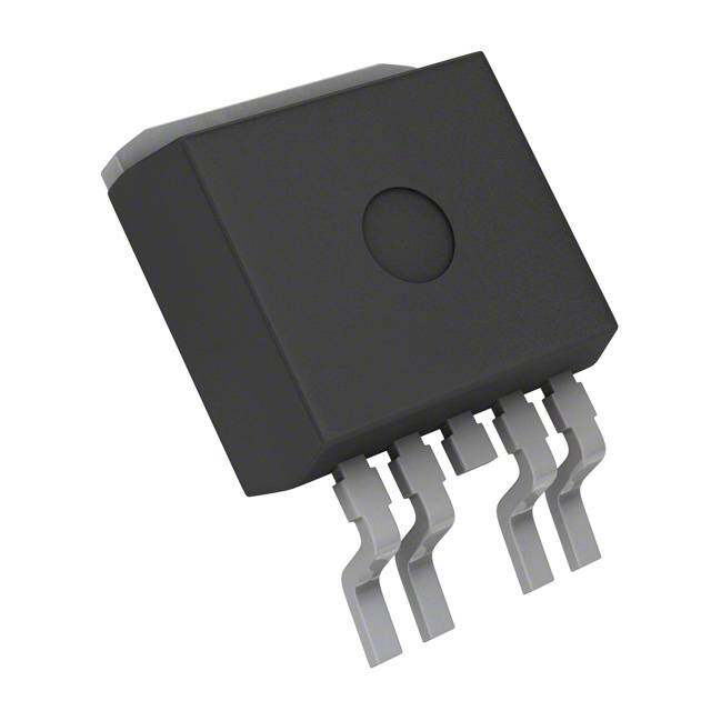
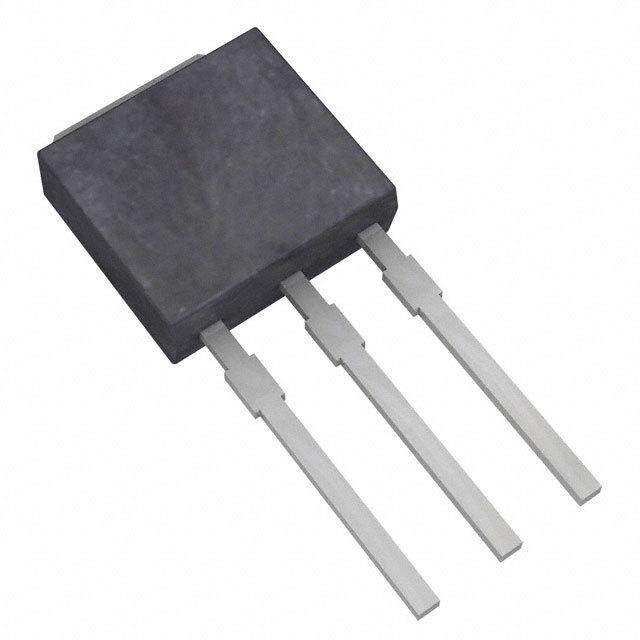
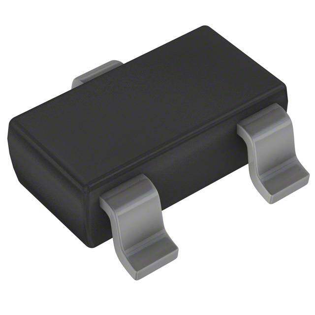
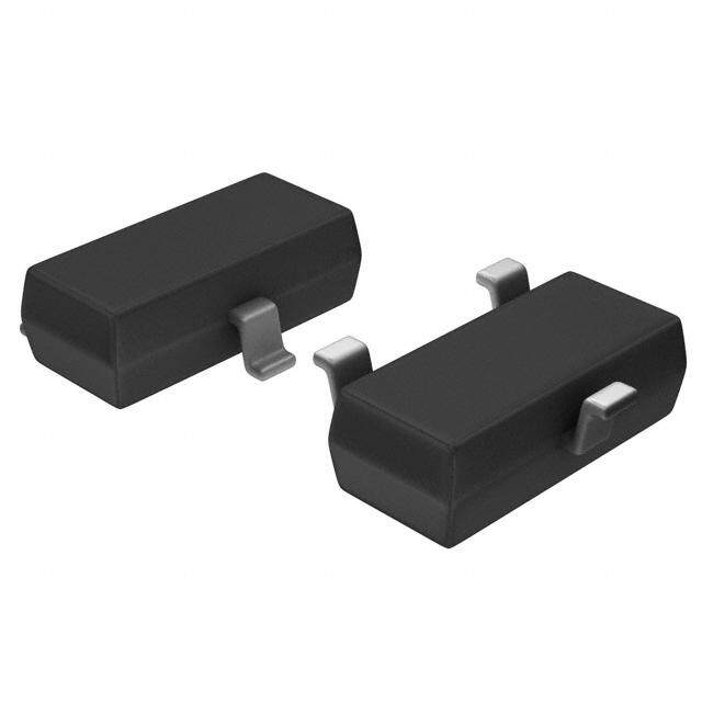
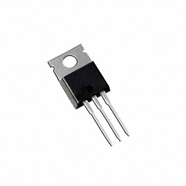
ICGOO电子元器件商城为您提供RSD100N10TL由ROHM Semiconductor设计生产,在icgoo商城现货销售,并且可以通过原厂、代理商等渠道进行代购。 RSD100N10TL价格参考。ROHM SemiconductorRSD100N10TL封装/规格:晶体管 - FET,MOSFET - 单, 表面贴装 N 沟道 100V 10A(Ta) 20W(Tc) CPT3。您可以下载RSD100N10TL参考资料、Datasheet数据手册功能说明书,资料中有RSD100N10TL 详细功能的应用电路图电压和使用方法及教程。
| 参数 | 数值 |
| 产品目录 | |
| 描述 | MOSFET N-CH 100V 10A CPT3 |
| 产品分类 | FET - 单 |
| FET功能 | 逻辑电平栅极,4V 驱动 |
| FET类型 | MOSFET N 通道,金属氧化物 |
| 品牌 | Rohm Semiconductor |
| 数据手册 | 点击此处下载产品Datasheet点击此处下载产品Datasheet点击此处下载产品Datasheet点击此处下载产品Datasheet |
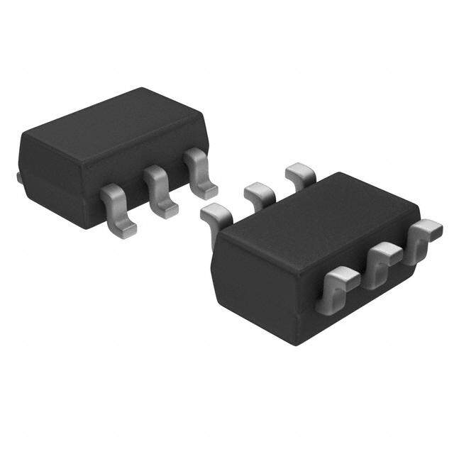
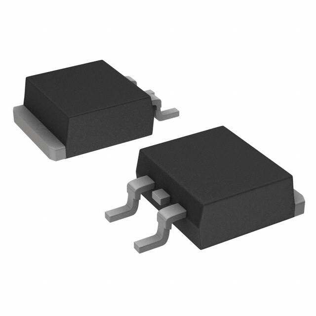
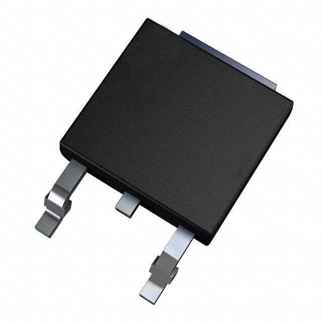
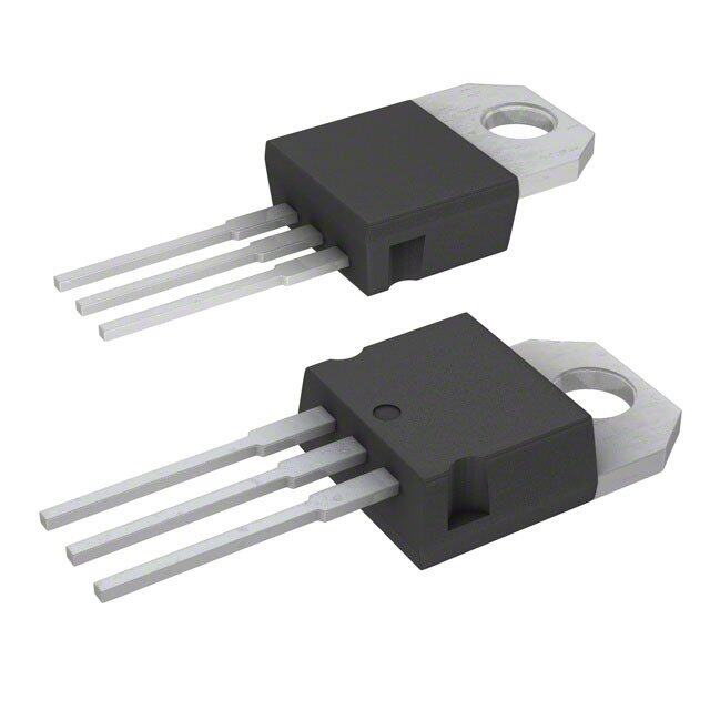
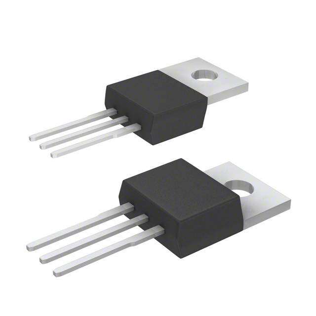
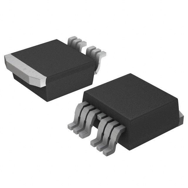
| 产品图片 |
|
| 产品型号 | RSD100N10TL |
| rohs | 无铅 / 符合限制有害物质指令(RoHS)规范要求 |
| 产品系列 | - |
| 不同Id时的Vgs(th)(最大值) | 2.5V @ 1mA |
| 不同Vds时的输入电容(Ciss) | 700pF @ 25V |
| 不同Vgs时的栅极电荷(Qg) | 18nC @ 10V |
| 不同 Id、Vgs时的 RdsOn(最大值) | 133 毫欧 @ 5A, 10V |
| 供应商器件封装 | CPT3 |
| 其它名称 | RSD100N10TL-ND |
| 功率-最大值 | 20W |
| 包装 | 带卷 (TR) |
| 安装类型 | 表面贴装 |
| 封装/外壳 | TO-252-3,DPak(2 引线+接片),SC-63 |
| 标准包装 | 2,500 |
| 漏源极电压(Vdss) | 100V |
| 电流-连续漏极(Id)(25°C时) | 10A (Ta) |

PDF Datasheet 数据手册内容提取
Data Sheet 4V Drive Nch MOSFET RSD100N10 Structure Dimensions (Unit : mm) r Silicon N-channel MOSFET CPT3 6.5 o (<SSCO-T6-432)8> 5.1 2.3 0.5 f5 1. Features 5 12)) L4oVw d roivne-r.esistance. d 0.9 5. 1.5 9.5 0.75 5 3) High power package. 2. e0.9(1)2.3(2) (3)02.6.35 0.8Min.0.5 1.0 d Application Switching s n n e Packaging specifications Inner circuit g Package Taping m ∗1 Type Code TL i Basic ordering unit (pieces) 2500 RSD100N10 m s ∗2 e o (1) (2) (3) D (1) Gate (2) Drain 1 ESD PROTECTION DIODE (3) Source c 2 BODY DIODE w e Absolute maximum ratings (Ta = 25C) ParameterR Symbol Limits Unit e Drain-source voltage V 100 V DSS Gate-source voltag e N VGSS 20 V t Continuous I *3 10 A Drain current D o Pulsed IDP *1 20 A Source current Continuous I *3 10 A S (BodNy Diode) Pulsed I *1 20 A SP Power dissipation P *2 20 W D Channel temperature Tch 150 C Range of storage temperature Tstg 55 to 150 C *1 P 10s, Duty cycle1% W *2 T =25°C C *3 Please use within the range of SOA. Thermal resistance Parameter Symbol Limits Unit Channel to Case Rth (ch-c)* 6.25 C / W * T =25°C C www.rohm.com © 2011 ROHM Co., Ltd. All rights reserved. 1/6 2011.06 - Rev.A
RSD100N10 Data Sheet Electrical characteristics (Ta = 25C) Parameter Symbol Min. Typ. Max. Unit Conditions Gate-source leakage I - - 10 A V =20V, V =0V GSS GS DS Drain-source breakdown voltage V 100 - - V I =1mA, V =0V (BR)DSS D GS Zero gate voltage drain current I - - 1 A V =100V, V =0V DSS DS GS Gate threshold voltage V 1 - 2.5 V V =10V, I =1mA GS (th) DS D - 95 133 ID=5A, VGS=10V r Static drain-source on-state * resistance RDS (on) - 100 140 m ID=5A, VGS=4.5V o - 105 147 I =5A, V =4V D GS Forward transfer admittance l Y l* 4.5 - - S V =10V, I =5A f fs DS D Input capacitance C - 700 - pF V =25V iss DS Output capacitance C - 65 - pF V =0V d oss GS Reverse transfer capacitance C - 40 - pF f=1MHz rss e Turn-on delay time t * - 10 - ns V 50V, I =5A d(on) DD D Rise time t * - 17 - ns V =10V r dGS Turn-off delay time t * - 50 - ns R =10 d(off) L Fall time t * - 20 - ns R =10 s f n G Total gate charge Q * - 18 - nC V 50V, I =10A g DD D n Gate-source charge Q * - 2 -e nC V =10V gs GS Gate-drain charge Q * - 4.5 - nC gd g m *Pulsed i s m Body diode characteristics (Source-Drain) e Parameter Symbol Min. Typ. Max. Unit Conditions Forward Voltage VSD* o- - D1.5 V Is=10A, VGS=0V *Pulsed c w e R e N t o N www.rohm.com © 2011 ROHM Co., Ltd. All rights reserved. 2/6 2011.06 - Rev.A
RSD100N10 Data Sheet Electrical characteristic curves (Ta=25C) Fig.1 Typical Output Characteristics (Ⅰ) Fig.2 Typical Output Characteristics (Ⅱ) 10 10 Ta=25°C VGS=2.8V Ta=25°C pulsed pulsed 8 VVGGSS==140..50VV 8 VVGGSS==140.5.0VV A] VGS=4.0V A] VGS=4.0V r Current : I [D 6 VGS=2.8V Current : I [D 6 foVGS=2.5V Drain 4 VGS=2.5V Drain 4 d 2 2 e VGS=2.0V VGS=2.0V 0 0 0 0.2 0.4 0.6 0.8 1 0 d2 4 6 8 10 Drain-Source Voltage : VDS [V] Drain-Source Voltage : VDS [V] s n Fig.3 Static Drain-Source On-State Resistance vs. Drain Current Fig.4 Static Drain-Source On-State Resistance vs. Drain Current n 1000 e1000 Drain-Source On-State Resistance R [mΩ] DS(on) 100 Tpua=ls2e5d° C VVVGGGoSSS===441..005VVV m m D Drain-Source On-State Resistance R [mΩ] eDS(on) 100 sVpuGlSsi=e1d0 V g TTTTaaaa====172-225555°°CC°°CC Static c Static w e 10 10 0.01 0.1 1 10 100 0.01 0.1 1 10 100 RDrain Current : ID [A] Drain Current : ID [A] e Fig.5 Static Drain-Source On-State Resistance vs. Drain Current Fig.6 Static Drain-Source On-State Resistance vs. Drain Current N 1000t 1000 VGS=4.5V VGS=4V o pulsed Ta=125°C pulsed Ta=125°C ance TTaa==7255°°CC ance TTaa==7255°°CC N esist Ta=-25°C esist Ta=-25°C R R e e StatΩ] StatΩ] ource On-R [mDS(on) 100 ource On-R [mDS(on) 100 S S n- n- ai ai Dr Dr c c ati ati St St 10 10 0.01 0.1 1 10 100 0.01 0.1 1 10 100 Drain Current : ID [A] Drain Current : ID [A] www.rohm.com © 2011 ROHM Co., Ltd. All rights reserved. 3/6 2011.06 - Rev.A
RSD100N10 Data Sheet Fig.7 Forward Transfer Admittance vs. Drain Current Fig.8 Typical Transfer Characteristics 100 100 VDS=10V VDS=10V pulsed pulsed 10 e 10 ward Transfer AdmittancY [S] fs 1 TTTTaaaa====172-225555°°CC°°CC Drain Currnt : I [A] D 0.11 TTTTaa==aa==1-27225555°°°°CCCC fo r or F 0.1 d 0.01 e 0.01 0.001 0.01 0.1 1 10 100 0.0 0d.5 1.0 1.5 2.0 2.5 3.0 3.5 Drain Current : ID [A] Gate-Source Voltage : VGS [V] s n Fig.9 Source Current vs. Source-Drain Voltage Fig.10 Static Drain-Source On-State Resistance vs. Gate-Source Voltage n 100 e 250 VGS=0V Ta=25°C pulsed pulsed g m e A] 10 TTaa==17255°C°C esistanc 200 i ID=10A Source Current : Is [ 1 TTaa==2-o255°C°C m n-Source On-State RR [mΩ] DS(on)e110500 s ID=5A D ai Dr 0.1 c c Stati 50 w e 0.01 0 0.0 0.5 1.0 1.5 2.0 0 2 4 6 8 10 RSource-Drain Voltage : VSD [V] Gate-Source Voltage : VGS [V] e Fig.11 Switching Characteristics Fig.12 Dynamic Input Characteristics N 10000t 10 VDD≒50V Ta=25°C o VGS=10V VDD=50V RG=10Ω ID=10A N e : t [ns] 1000 tf TPau=ls2e5d°C ge : V [V] GS 68 Pulsed m a Ti td(off) olt ng 100 e V Switchi td(on) ate-Sourc 4 G 10 2 tr 1 0 0.01 0.1 1 10 100 0 2 4 6 8 10 12 14 16 18 20 Drain Current : ID [A] Total Gate Charge : Qg [nC] www.rohm.com © 2011 ROHM Co., Ltd. All rights reserved. 4/6 2011.06 - Rev.A
RSD100N10 Data Sheet Fig.13 Typical Capacitance vs. Drain-Source Voltage Fig.14 Normalized Transient Thermal Resistance v.s. Pulse Width 10000 10 TfV=aG1=SM2=50H°VzC ()e :rt 1 TSain=g2l5e° PCu lse c n sta r C [pF] 1000 Ciss al Resi 0.1 o Capacitance : 100 ansient Therm 0.01 f Tr d d e Mounted on a recommended land. Coss aliz 0.001 (20mm × 20mm × 0.8mm) m Crss Nor eRRtthh((cchh--aa))=(t1)=1r1(t.)7×°CR/Wth( ch-a) 10 0.0001 0.01 0.1 1 10 100 1000 0.0001 0d.001 0.01 0.1 1 10 100 1000 Drain-Source Voltage : VDS [V] Pulse width : Pw (s) s n Fig.15 Maximum Safe Operating Area n 100 e Operation in this area is limited by RDS(on) (VGS = 10V) g m 10 A ] i [ s ent : ID 1 PW = 100μs m e urr C Drain oPW = 1ms D 0.1 PW = 10ms c DC Operation TC=25°C Single Pulse w e 0.01 0.1 1 10 100 1000 DRrain-Source Voltage : VDS [ V ] e N t o N www.rohm.com © 2011 ROHM Co., Ltd. All rights reserved. 5/6 2011.06 - Rev.A
RSD100N10 Data Sheet Measurement circuits Pulse width VGS ID VDS 50% 90% 50% RL VGS 10% VDS D.U.T. 10% 10% RG VDD 90% 90% r td(on) tr td(off) tf o ton toff Fig.1-1 Switching Time Measurement Circuit Fig.1-2 Switching Waveforms f d VG VGS ID e VDS Qg RL VGS d IG(Const.) D.U.T. Qgs Qgd VDD s n Charge n e Fig.2-1 Gate Charge Measurement Circuit Fig.2-2 Gate Charge Waveform g m i s m e o D c w e R e N t o N www.rohm.com © 2011 ROHM Co., Ltd. All rights reserved. 6/6 2011.06 - Rev.A
Notice Notes r o f d e d s n n e g m i s m e o D c w e R e N t o N Thank you for your accessing to ROHM product informations. More detail product informations and catalogs are available, please contact us. ROHM Customer Support System http://www.rohm.com/contact/ www.rohm.com R1120A © 2011 ROHM Co., Ltd. All rights reserved.
Mouser Electronics Authorized Distributor Click to View Pricing, Inventory, Delivery & Lifecycle Information: R OHM Semiconductor: RSD100N10TL

 Datasheet下载
