ICGOO在线商城 > 电阻器 > 芯片电阻 - 表面安装 > RC0805FR-07215KL
 Datasheet下载
- 型号: RC0805FR-07215KL
- 制造商: YAGEO AMERICA CORPORATION
- 库位|库存: xxxx|xxxx
- 要求:
| 数量阶梯 | 香港交货 | 国内含税 |
| +xxxx | $xxxx | ¥xxxx |
查看当月历史价格
查看今年历史价格
RC0805FR-07215KL产品简介:
ICGOO电子元器件商城为您提供RC0805FR-07215KL由YAGEO AMERICA CORPORATION设计生产,在icgoo商城现货销售,并且可以通过原厂、代理商等渠道进行代购。 RC0805FR-07215KL价格参考。YAGEO AMERICA CORPORATIONRC0805FR-07215KL封装/规格:芯片电阻 - 表面安装, 215 kOhms ±1% 0.125W,1/8W 厚膜 芯片电阻 0805(2012 公制) 防潮 厚膜。您可以下载RC0805FR-07215KL参考资料、Datasheet数据手册功能说明书,资料中有RC0805FR-07215KL 详细功能的应用电路图电压和使用方法及教程。
| 参数 | 数值 |
| 产品目录 | |
| 描述 | RES 215K OHM 1/8W 1% 0805 SMD |
| 产品分类 | |
| 品牌 | Yageo |
| 数据手册 | |
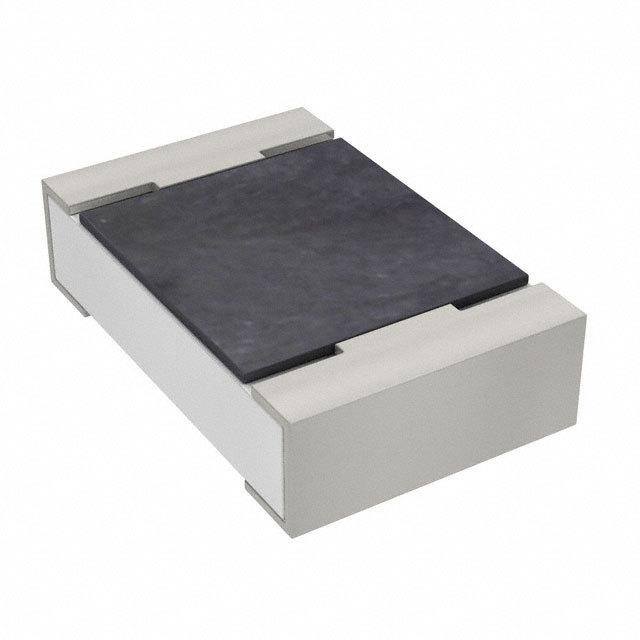
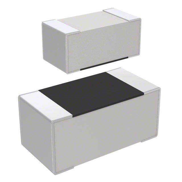
| 产品图片 |
|
| 产品型号 | RC0805FR-07215KL |
| PCN其它 | |
| rohs | 无铅 / 符合限制有害物质指令(RoHS)规范要求 |
| 产品系列 | RC0805 |
| 产品培训模块 | http://www.digikey.cn/PTM/IndividualPTM.page?site=cn&lang=zhs&ptm=4919 |
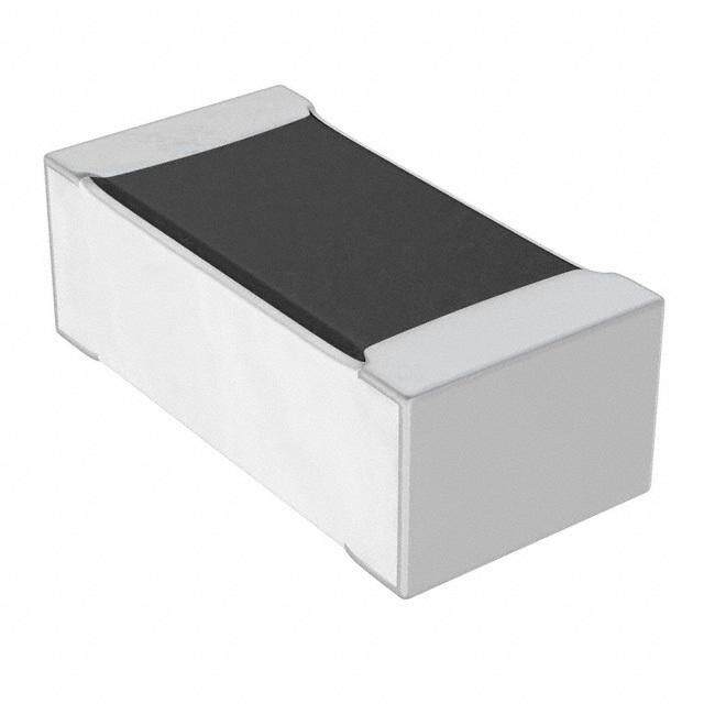
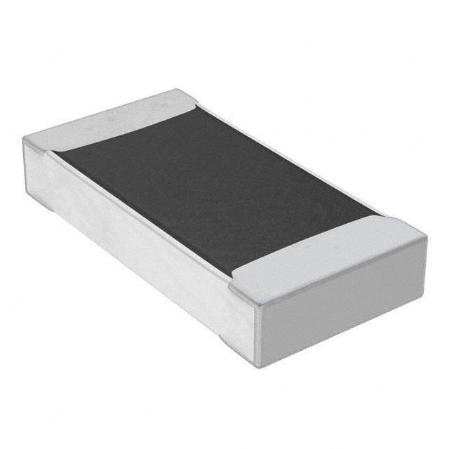
| 产品目录绘图 |
|
| 产品目录页面 | |
| 供应商器件封装 | 0805 |
| 其它名称 | 311-215KCRDKR |
| 功率(W) | 0.125W,1/8W |
| 包装 | Digi-Reel® |
| 大小/尺寸 | 0.079" 长 x 0.049" 宽(2.00mm x 1.25mm) |
| 容差 | ±1% |
| 封装/外壳 | 0805(2012 公制) |
| 工作温度 | -55°C ~ 155°C |
| 工具箱 | /product-detail/zh/PHC6A-KIT/PHC6A-KIT-ND/383634/product-detail/zh/PHC6-KIT/PHC6-KIT-ND/383635 |
| 成分 | 厚膜 |
| 标准包装 | 1 |
| 温度系数 | ±100ppm/°C |
| 特性 | 防潮 |
| 电阻(Ω) | 215k |
| 端子数 | 2 |
| 高度 | 0.024"(0.60mm) |


PDF Datasheet 数据手册内容提取
DATA SHEET GENERAL PURPOSE CHIP RESISTORS RC_L series ±0.1%, ±0.5%, ±1%, ±5% Sizes 0075/0100/0201/0402/0603/0805/ 1206/1210/1218/2010/2512 RoHS compliant & Halogen free 0 1 V. 8 1 0 2 2, 1 r e b m e c e D – n o ti a c cifi e p s t c u d o r P
Product specification 2 Chip Resistor Surface Mount RC_L SERIES 0075 to 2512 10 SCOPE ORDERING INFORMATION - GLOBAL PART NUMBER This specification describes RC Global part numbers are identified by the series, size, tolerance, packing series chip re sistors with lead type, temperature coefficient, taping reel and resistance value. free terminat ions made by thick film process. G LOBAL PART NUMBER RC XXXX X X X XX XXXX L (1) (2) (3) (4) (5) (6) (7) APPLICATIONS All general purpose application (1) SIZE 0075/0100/0201/0402/0603/0805/1206/1210/1218/2010/2512 (2) TOLERANCE FEATURES B = ±0.1% Halogen Free Epoxy D = ±0.5% RoHS compliant F = ±1.0% Products with lead free J = ±5.0% (for jumper ordering, use code of J) terminations meet RoHS (3) PACKAGING TYPE requirements Pb-glass contained in R = Paper taping reel electrodes, resistors element K = Embossed taping reel and glass are exempted by S = ESD safe reel (0075/0100 only) RoHS (4) TEMPERATURE COEFFICIENT OF RESISTANCE Reducing environmentally hazardous wastes - = Based on spec. High component and equipment (5) TAPING REEL reliability 07 = 7 inch dia. Reel Saving of PCB space 10=10 inch dia. Reel None forbidden-materials used in 13 =13 inch dia. Reel products/production 7W = 7 inch dia. Reel & 2 x standard power 7N = 7 inch dia. Reel, ESD safe reel (0075/0100 only) 3W = 13 inch dia. Reel & 2 x standard power (6) RESISTANCE VALUE There are 2~4 digits indicated the resistance value. Letter R/K/M is decimal point Example: 97R6 = 97.6Ω 9K76 = 9760Ω 1M = 1,000,000Ω (7) DEFAULT CODE Letter L is the system default code for ordering only.(Note) ORDERING EXAMPLE The ordering code for a RC0402 0.0625W chip resistor value 100KΩwith ±5% tolerance, supplied in 7-inch tape reel of 10,000 units per reel is: RC0402JR-07100KL. NOTE 1. All our RSMD products meet RoHS compliant and Halogen Free. "LFP" of the internal 2D reel label mentions "Lead Free Process". 2. On customized label, "LFP" or specific symbol can be printed. www.yageo.com Dec. 12, 2018 V.10
Product specification 3 Chip Resistor Surface Mount RC_L SERIES 0075 to 2512 10 MARKING RC0075 / RC0100 / RC0201 / RC0402 No Marking Fig. 1 R C 0603 0 1%, 0.5%,E24 exception values 10/11/13/15/20/75 of E24 series Fig. 2 240 = 24 × 100 = 24 88 1%, 0.5%, E96 refer to EIA-96 marking method, including values 10/11/13/15/20/75 of E24 series Fig. 3 88A = 806 × 100 = 806 Ω 03 5%, E24 series : 3 digits First two digits for significant figure and 3rd digit for number of zeros F ig. 4 Value = 10 KΩ RC0805 / RC1206 / RC1210 / RC2010 / RC2512 00 1%, 0.5%, E24/E96 series : 4 digits First three digits for significant figure and 4th digit for number of zeros Fig. 5 Value = 10 KΩ PF series Note: construction will be adjusted to resistance value 03 5%, E24 series : 3 digits (only for PF series). First two digits for significant figure and 3rd digit for number of zeros Fig. 6 Value = 10 KΩ RC 1218 E-24 series: 3 digits, ±5% First two digits for significant figure and 3rd digit for number of zeros Fig. 7 Value = 10 KΩ 00 Both E-24 and E-96 series: 4 digits, ±1% & ±0.5% First three digits for significant figure and 4th digit for number of zeros Fig. 8 Value = 10 KΩ F or further marking information, please see special data sheet "Chip resistors marking". www.yageo.com Dec. 12, 2018 V.10
Product specification 4 Chip Resistor Surface Mount RC_L SERIES 0075 to 2512 10 OOuuttlliinneess CONSTRUCTION The resistor is constructed on top of a high-grade For dimensions, please refer to Table 1 ceramic body . Internal metal electrodes are added on each end t o make the contacts to the thick film resistive element. The composition of the resistive element is a noble metal imbedded into a glass and covered by a second glass to prevent environmenta l influences. The resistor is laser trimmed to the rated resistance value. The resistor is covered with a protective epoxy coat, finally the two external terminations (matte tin on Ni-barrier) are added, as shown in Fig.9. 9 Fig. 9 Chip resistor outlines DIMENSION Table 1 T YPE L (mm) W (mm) H (mm) I1 (mm) I2 (mm) RC0075 0.30±0.015 0.15±0.015 0.13±0.02 0.08±0.03 0.08±0.03 R C0100 0.40±0.02 0.20±0.02 0.13±0.02 0.10±0.03 0.10±0.03 R C0201 0.60±0.03 0.30±0.03 0.23±0.03 0.10±0.05 0.15±0.05 R C0402 1.00±0.05 0.50±0.05 0.35±0.05 0.20±0.10 0.25±0.10 R C0603 1.60±0.10 0.80±0.10 0.45±0.10 0.25±0.15 0.25±0.15 RC0805 2.00±0.10 1.25±0.10 0.50±0.10 0.35±0.20 0.35±0.20 R C1206 3.10±0.10 1.60±0.10 0.55±0.10 0.45±0.20 0.40±0.20 R C1210 3.10±0.10 2.60±0.15 0.55±0.10 0.45±0.15 0.50±0.20 RC1218 3.10±0.10 4.60±0.10 0.55±0.10 0.45±0.20 0.40±0.20 R C2010 5.00±0.10 2.50±0.15 0.55±0.10 0.45±0.15 0.50±0.20 RC2512 6.35±0.10 3.10±0.15 0.55±0.10 0.60±0.20 0.50±0.20 ELECTRICAL CHARACTERISTICS Table 2 CHARAC- POWER OPERATING MAXIMUM MAXIMUM DIELECTRIC RESISTANCE TEMPERATURE JUMPER TERISTICS TEMPERATURE WORKING OVERLOAD WITHSTANDING RANGE COEFFICIENT CRITERIA RANGE VOLTAGE VOLTAGE VOLTAGE 5% (E24) 10Ω≦R<100Ω Rated Current 10Ω≦R≦1MΩ -200~+600ppm℃ 0.5A FRigC. 040 7C5 hip resis1t/o50r oWu tline-s5 5℃ to 125℃ 10V 25V 25V 1% (E24/E96) 100Ω≦R≦1MΩ MCaxuirmreunmt 10Ω≦R≦1MΩ ±200ppm℃ 1.0A Jumper<50mΩ 5% (E24) 1Ω≦R<10Ω Rated Current 1Ω≦R≦22MΩ -200~+600ppm℃ 0.5A Maximum 1% (E24/E96) 10Ω≤ R < 100Ω: Current RC0100 1/32 W -55℃ to 125℃ 15V 30V 30V 1Ω≦R≦10MΩ ±300ppm/°C 1.0A 0.5% (E24/E96) 100Ω≤ R ≤ 10MΩ: 33Ω≦R≦470KΩ ±200ppm/°C Jumper<50mΩ 10MΩ< R ≤ 22MΩ: ±250ppm/°C www.yageo.com Dec. 12, 2018 V.10
Product specification 5 Chip Resistor Surface Mount RC_L SERIES 0075 to 2512 10 Table 2 CHARAC- POWER OPERATING MAXIMUM MAXIMUM DIELECTRIC RESISTANCE TEMPERATURE JUMPER TERISTICS TEMPERATURE WORKING OVERLOAD WITHSTANDING RANGE COEFFICIENT CRITERIA RANGE VOLTAGE VOLTAGE VOLTAGE 5% (E24) 1Ω≦R≦10Ω Rated Current 1Ω≦R≦10MΩ -100~+350ppm℃ 0.5A Maximum 1% (E24/E96) 10Ω<R≦10MΩ Current RC0201 1/20 W -55℃ to 125℃ 25V 50V 50V 1Ω≦R≦10MΩ ±200ppm℃ 1.0A 0.1%, 0.5% (E24/E96) 10Ω≦R≦1MΩ Jumper<50mΩ 5% (E24) 1Ω≦R≦10Ω R a t ed Current 1Ω≦R≦22MΩ ±200ppm℃ 1.0A 1% (E24/E96) Maximum 10Ω<R≦10MΩ Current 1/16 W -55℃ to 155℃ 50V 100V 100V 1Ω≦R≦10MΩ ±100ppm℃ 2.0A 0.1%, 0.5% (E24/E96) 10MΩ<R≦22MΩ RC0402 10Ω≦R≦1MΩ ±200ppm℃ Jumper<50mΩ 5% (E24) 1Ω≦R≦1MΩ 1Ω≦R≦1MΩ 1/8W -55℃ to 155℃ 50V 100V 100V 1% (E24/E96) ±200ppm℃ 1Ω≦R≦1MΩ 5% (E24) 1Ω≦R≦10Ω R a t ed Current 1Ω≦R≦22MΩ ±200ppm℃ 1.0A 1% (E24/E96) Maximum 10Ω<R≦10MΩ Current 1/10 W -55℃ to 155℃ 75V 150V 150V 1Ω≦R≦10MΩ ±100ppm℃ 2.0A 0.1%, 0.5% (E24/E96) 10MΩ<R≦22MΩ RC0603 10Ω≦R≦1MΩ ±200ppm℃ Jumper<50mΩ 5% (E24) 1Ω≦R≦1MΩ 1Ω≦R≦1MΩ ±200ppm℃ 1/5 W -55℃ to 155℃ 75V 150V 150V 1% (E24/E96) 1Ω≦R≦1MΩ 5% (E24) 1Ω≦R≦10Ω R a t e d Current 1Ω≦R≦100MΩ ±200ppm℃ 2.0A 1% (E24/E96) Maximum 10Ω<R≦10MΩ Current 1Ω≦R≦10MΩ ±100ppm℃ 5.0A 1/8 W -55℃ to 155℃ 150V 300V 300V 0.1%, 0.5% (E24/E96) 10MΩ<R≦22MΩ 10Ω≦R≦1MΩ 10%, 20% (E24) ±200ppm℃ RC0805 24MΩ≦R≦100MΩ 24MΩ<R≦100MΩ Jumper<50mΩ ±300ppm℃ 5% (E24) 1Ω≦R≦1MΩ 1Ω≦R≦1MΩ 1/4 W -55℃ to 155℃ 150V 300V 300V ±200ppm℃ 1% (E24/E96) 1Ω≦R≦1MΩ www.yageo.com Dec. 12, 2018 V.10
Product specification 6 Chip Resistor Surface Mount RC_L SERIES 0075 to 2512 10 FOOTPRINT AND SOLDERING PROFILES For recommended footprint and soldering profiles, please refer to data sheet “Chip resistors mounting” Table 2 CHARAC- PO WER OPERATING MAXIMUM MAXIMUM DIELECTRIC RESISTANCE TEMPERATURE JUMPER TERISTICS TEMPERATURE WORKING OVERLOAD WITHSTANDING RANGE COEFFICIENT CRITERIA RANGE VOLTAGE VOLTAGE VOLTAGE 5% (E24) 1Ω≦R≦10Ω R a t e d Current 1Ω≦R≦100MΩ ±200ppm℃ 2.0A Maximum 1% (E24/E96) 10Ω<R≦10MΩ Current 1Ω≦R≦10MΩ ±100ppm℃ 10.0A 1/4 W -55℃ to 155℃ 200V 400V 500V 0.1%, 0.5% (E24/E96) 10MΩ<R≦22MΩ 10Ω≦R≦1MΩ 10%, 20% (E24) ±200ppm℃ RC1206 24MΩ≦R≦100MΩ 24MΩ≦R≦100MΩ Jumper<50mΩ ±300ppm℃ 5% (E24) 1Ω≦R≦1MΩ 1Ω≦R≦1MΩ ±200ppm℃ 1/2 W -55℃ to 155℃ 200V 400V 500V 1% (E24/E96) 1Ω≦R≦1MΩ 5% (E24) 1Ω≦R≦10Ω R a t ed Current 1Ω≦R≦22MΩ ±200ppm℃ 2.0A Maximum 1% (E24/E96) 10Ω<R≦10MΩ Current RC1210 1/2 W -55℃ to 155℃ 200V 500V 500V 1Ω≦R≦10MΩ ±100ppm℃ 10.0A 0.1%, 0.5% (E24/E96) 10MΩ<R≦22MΩ 10Ω≦R≦1MΩ ±200ppm℃ Jumper<50mΩ 5% (E24) 1Ω≦R≦10Ω R a t ed Current 1Ω≦R≦1MΩ ±200ppm℃ 6.0A 1% (E24/E96) 10Ω<R≦1MΩ Maximum RC1218 1 W -55℃ to 155℃ 200V 500V 500V 1Ω≦R≦1MΩ ±100ppm℃ Current 0.1%, 0.5% (E24/E96) 10.0A 10Ω≦R≦1MΩ Jumper<50mΩ 5% (E24) 1Ω≦R≦10Ω R a t ed Current 1Ω≦R≦22MΩ ±200ppm℃ 2.0A 1% (E24/E96) 10Ω<R≦10MΩ Maximum RC2010 3/4 W -55℃ to 155℃ 200V 500V 500V 1Ω≦R≦10MΩ ±100ppm℃ Current 0.1%, 0.5% (E24/E96) 10MΩ<R≦22MΩ 10.0A 10Ω≦R≦1MΩ ±200ppm℃ Jumper<50mΩ 5% (E24) 1Ω≦R≦10Ω R a t ed Current 1Ω≦R≦22MΩ ±200ppm℃ 2.0A 1% (E24/E96) 10Ω<R≦10MΩ Maximum 1 W -55℃ to 155℃ 200V 500V 500V 1Ω≦R≦10MΩ ±100ppm℃ Current 0.1%, 0.5% (E24/E96) 10MΩ<R≦22MΩ 10.0A RC2512 10Ω≦R≦1MΩ ±200ppm℃ Jumper<50mΩ 5% (E24) 1Ω≦R≦1MΩ 1Ω≦R≦1MΩ ±200ppm℃ 2 W -55℃ to 155℃ 200V 400V 500V 1% (E24/E96) 1Ω≦R≦1MΩ www.yageo.com Dec. 12, 2018 V.10
Product specification 7 Chip Resistor Surface Mount RC_L SERIES 0075 to 2512 10 PACKING STYLE AND PACKAGING QUANTITY Table 3 Packing style and packaging quantity PACKING STY LE PAPER TAPING REEL (R) ESD SAFE REEL (S) EMBOSSED (4MM WIDTH, 1MM TAPING REEL PITCH PLASTIC EMBOSSED) REEL DIMENSION 7" (178 mm) 10" (254mm) 13" (330 mm) 7" (178 mm) 7" (178 mm) RC0075 --- --- --- 20000 --- RC0100 20000 --- 80000 40000 --- RC0201 10000 20000 50000 --- --- RC0402 10000 20000 50000 --- --- RC0603 5000 10000 20000 --- --- RC0805 5000 10000 20000 --- --- RC1206 5000 10000 20000 --- --- RC1210 5000 10000 20000 --- --- RC1218 --- --- --- --- 4000 RC2010 --- --- --- --- 4000 RC2512 --- --- --- --- 4000 NOTE For tape and reel specification/dimensions, please refer to data sheet “Chip resistors packing”. FUNCTIONAL DESCRIPTION OOPPEERRAATTIINNGG TTEEMMPPEERRAATTUURREE RRAANNGGEE RC0402 to RC2512 Range: -55℃ to +155℃ (Fig. 10-1) RC0075 to RC0201 Range: -55℃ to +125℃ (Fig. 10-2) PPOOWWEERR RRAATTIINNGG Each type rated power at 70 °C: RC0075=1/50W RC0100=1/32W RC0201=1/20W RC0402=1/16W, 1/8W RC0603=1/10W, 1/5W RC0805=1/8W, 1/4W Fig. 10-1 Maximum dissipation (P) in percentage of rated poweras a function of the operating ambient RC1206=1/4W, 1/2W temperature (Tamb) RC1210=1/2W RC1218=1W RC2010=3/4W RC2512=1W, 2W RATED VOLTAGE The DC or AC (rms) continuous working voltage corresponding to the rated power is determined by the following formula: V = (PxR) or max. working voltage whichever is less Where V = Continuous rated DC or AC (rms) working voltage (V) Fig. 10-2 Maximum dissipation (P) in percentage of rated P = Rated power (W) pteomwpeerraast ua rfeu n(Tctaiomnb )o f the operating ambient R = Resistance value (Ω) www.yageo.com Dec. 12, 2018 V.10
Product specification 8 Chip Resistor Surface Mount RC_L SERIES 0075 to 2512 10 TESTS AND REQUIREMENTS Table 8 Test condition, procedure and requirements TEST TEST METHOD PROCEDURE REQUIREMENTS Temperature MIL-STD-202 Method 304 At +25/–55°C and +25/+125°C Refer to table 2 Coefficient of Resistance Formula: (T.C.R.) T.C.R= R2R1 ×106 (ppm/°C) R1(t2t1) Where t =+25 °C or specified room temperature 1 t =–55 °C or +125 °C test temperature 2 R =resistance at reference temperature in ohms 1 R =resistance at test temperature in ohms 2 Life/ Endurance MIL-STD-202 Method 108A At 70±2°C for 1,000 hours; RCWV applied for 0075: ± (5%+100mΩ) IEC 60115-1 4.25.1 1.5 hours on and 0.5 hour off, still air required <100mΩ for jumper 01005: ±(3% +50mΩ) <100mΩf or jumper Others: ±(1%+50mΩ) for B/D/F tol ±(3%+50mΩ) for J tol <100mR for jumper High MIL-STD-202 Method 108A 1,000 hours at maximum operating temperature 0075: ± (5%+100mΩ) Temperature IEC 60068-2-2 depending on specification, unpowered. <100mΩ for jumper Exposure 01005: ±(1% +50mΩ) < 50mΩf or jumper Others: ±(1%+50mΩ) for B/D/F tol ±(2%+50mΩ) for J tol <50mR for jumper Moisture MIL-STD-202 Method 106G Each temperature / humidity cycle is defined at 0075: ± (2%+100mΩ) Resistance 8 hours (method 106F), 3 cycles / 24 hours for <100mΩ for jumper 01005: ±(2% +50mΩ) 10d with 25°C / 65°C 95% R.H, without steps < 100mΩf or jumper 7a & 7b, unpowered Others: Parts mounted on test-boards, without ±(0.5%+50mΩ) for B/ D/F tol condensation on parts ±(2%+50mΩ) for J tol <100mR for jumper Humidity IEC 60115-1 4.24.2 Steady state for 1000 hours at 40°C / 95% R.H. 0075: ± (5%+100mΩ) no visible damage RCWV applied for 1.5 hours on and 01005: ±(3% +50mΩ) 0.5 hour off < 100mΩf or jumper Others: ±(1%+50mΩ) for B/D/F tol ±(2%+50mΩ) for J tol <100mR for jumper www.yageo.com Dec. 12, 2018 V.10
Product specification 9 Chip Resistor Surface Mount RC_L SERIES 0075 to 2512 10 Thermal MIL-STD-202 Method 107G -55/+125°C 0075/01005: ±(1% +50mΩ) Shock < 50mΩf or jumper Note Number of cycles required is 300. Others: Devices mounted ±(0.5%+50mΩ) for B/D/F tol Maximum transfer time is 20 seconds. Dwell time is 15 minutes. Air - Air ±(1%+50mΩ) for J tol < 50mR for jumper Short Time IEC 60115-1 4.13 2.5 times RCWV or maximum overload voltage 0075/01005: ±(2% +50mΩ) Overload which is less for 5 seconds at room temperature < 50mΩf or jumper Others: ±(1%+50mΩ) for B/D/F tol ±(2%+50mΩ) for J tol <50mR for jumper No visible damage Board Flex/ IEC 60115-1 4.33 Device mounted or as described only 1 board 0075/01005: ±(1% +50mΩ) Bending bending required < 50mΩf or jumper Others: bending time: 60±5 seconds ±(1%+50mΩ) for B/D/F/J tol 0075/0100/0201/0402:5mm; 0603/0805:3mm; <50mR for jumper 1206 and above:2mm No visible damage Solderability J-STD-002 test B Electrical Test not required Magnification 50X W ell tinned - Wetting SMD conditions: (>95% covered) 1st step: method B, aging 4 hours at 155°C No visible damage dry heat 2nd step: leadfree solder bath at 245±3°C Dipping time: 3±0.5 seconds -Leaching J-STD-002 test D Leadfree solder ,260°C, 30 seconds immersion No visible damage time -Resistance to MIL-STD-202 Method 210F Condition B, no pre-heat of samples 0075: ± (3%+50mΩ) Soldering Heat IEC 60115-1 4.18 Leadfree solder, 260°C ±5°C, 10 ±1 seconds <50mΩ for jumper 01005: ±(1% +50mΩ) immersion time < 50mΩf or jumper Procedure 2 for SMD: devices fluxed and Others: cleaned with isopropanol ±(0.5% +50mΩ) for B/D/F tol. ±(1% +50mΩ) for J tol. <50mR for jumper No visible damage www.yageo.com Dec. 12, 2018 V.10
Product specification 10 Chip Resistor Surface Mount RC_L SERIES 0075 to 2512 10 REVISION HISTORY REVISION DATE CHANGE NOTIFICATION DESCRIPTION TEMPERATURE COEFFICIENT Version 1T0 YPE Dec. 12, 2018 - POWER TOL-E URpAdNatCedE 0075R dEiSmISeTnAsioNnCs E RANGE OF RESISTANCE 0603 Version 9 Mar. 016/, 1200W18, 1/5- W, 3/10W, 2/5W, 1/2W - Add 0.5%/1% mark5i nmg Ωru≦le R f o<r 1R0C0 0m6Ω03 ~ RC2512 based on marking 0805 1/8W, 1/4W, 1/3W, 1/2W datasheet 4 mΩ ≦ R < 100 mΩ Version 8 July 10, 2017 - - Add "3W" part number coding for 13" Reel & double power 1206 1/4W, 1/2W 3 mΩ ≦ R < 100 mΩ Version 7 Mar.1 7/2, W20,1 17W - - Add 10" packing The resistors are constructed using outstanding TCR level Version 6 Feb.1m5a, t2e0r1ia7l , wh- ich makes Yageo PF - Extend RC0805 and RC1206 resistance range to 100Mohm resistors excellent for current Version 5 Oct.s 0e6n,s 2in0g1 6a pp-li cation in battery - Description: Update Dimension of I2 of RC2512 (2W) charger circuit & DC-DC converter. Version 4 Jan. 22, 2016 - - Update resistance range The composition of the resistive ±1% PF 2010 material is adjusted to give the ±2% 5 mΩ ≦ R < 100 mΩ ±75 ppm/°C Version 3 Deca. 2p4p,r 2o0x1i5m at-e required resistance - Updated test and requirements ±5% and is covered with a protective coating, which printed with the Version 2 Jul. 23, 2015 - - Updated test and requirements resistance value. Finally, the three external Version 1 Jan. 2te1r, m20i1n5a tion-s (Ni / matte Tin) are - ESD Safe Reel update added, as shown in Fig. 4. Version 0 Dec. 15, 2014 - - First issue of this specification 1W, 2W 1 mΩ ≦ R < 100 mΩ 2512 3W 1 mΩ ≦ R ≦ 50 mΩ 4527 2W, 3W, 5W 6 mΩ ≦ R < 1Ω NOTE: 1. PLEASE CONTACT WITH SALES OFFICES, DISTRIBUTORS AND REPRESENTATIVES IN YOUR REGION BEFORE ORDERING “ Yageo reserves all the rights for revising the content of this datasheet without further notification, as long as the products itself are unchanged. Any product change will be announced by PCN.” www.yageo.com Dec. 12, 2018 V.10