ICGOO在线商城 > Q6040K7
 Datasheet下载
- 型号: Q6040K7
- 制造商: Littelfuse
- 库位|库存: xxxx|xxxx
- 要求:
| 数量阶梯 | 香港交货 | 国内含税 |
| +xxxx | $xxxx | ¥xxxx |
查看当月历史价格
查看今年历史价格
Q6040K7产品简介:
ICGOO电子元器件商城为您提供Q6040K7由Littelfuse设计生产,在icgoo商城现货销售,并且可以通过原厂、代理商等渠道进行代购。 提供Q6040K7价格参考以及LittelfuseQ6040K7封装/规格参数等产品信息。 你可以下载Q6040K7参考资料、Datasheet数据手册功能说明书, 资料中有Q6040K7详细功能的应用电路图电压和使用方法及教程。
| 参数 | 数值 |
| GateTriggerCurrent-Igt | 100 mA |
| GateTriggerVoltage-Vgt | 2.5 V |
| 品牌 | Littelfuse |
| 产品目录 | 半导体 |
| 描述 | 双向可控硅 600V 40A 100-100-100mA |
| 产品分类 | 分离式半导体 |
| 产品手册 | |
| 产品图片 |
|
| rohs | 符合RoHS |
| 产品系列 | 晶体闸流管,双向可控硅,Littelfuse Q6040K7 |
| 产品型号 | Q6040K7 |
| 不重复通态电流 | 335 A, 400 A |
| 产品种类 | 双向可控硅 |
| 保持电流Ih最大值 | 120 mA |
| 关闭状态漏泄电流(在VDRMIDRM下) | 200 uA |
| 商标 | Littelfuse |
| 安装风格 | Through Hole |
| 封装 | Bulk |
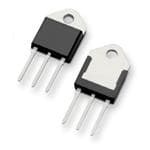
| 封装/箱体 | TO-218-3 |
| 工厂包装数量 | 250 |
| 开启状态RMS电流-ItRMS | 40 A |
| 开启状态电压 | 1.8 V |
| 最大工作温度 | + 125 C |
| 最小工作温度 | - 40 C |
| 栅极触发电压-Vgt | 2.5 V |
| 栅极触发电流-Igt | 100 mA |
| 系列 | Qxx40xx |
| 额定重复关闭状态电压VDRM | 600 V |


- 商务部:美国ITC正式对集成电路等产品启动337调查
- 曝三星4nm工艺存在良率问题 高通将骁龙8 Gen1或转产台积电
- 太阳诱电将投资9.5亿元在常州建新厂生产MLCC 预计2023年完工
- 英特尔发布欧洲新工厂建设计划 深化IDM 2.0 战略
- 台积电先进制程称霸业界 有大客户加持明年业绩稳了
- 达到5530亿美元!SIA预计今年全球半导体销售额将创下新高
- 英特尔拟将自动驾驶子公司Mobileye上市 估值或超500亿美元
- 三星加码芯片和SET,合并消费电子和移动部门,撤换高东真等 CEO
- 三星电子宣布重大人事变动 还合并消费电子和移动部门
- 海关总署:前11个月进口集成电路产品价值2.52万亿元 增长14.8%


PDF Datasheet 数据手册内容提取
Teccor® brand Thyristors 15 Amp Standard & 16 Amp Alternistor (High Commutation) Triacs Qxx15xx & Qxx16xHx Series RoHS Description The 15 Amp and 16 Amp bi-directional solid state switch series are designed for AC switching and phase control applications such as motor speed, temperature modulation controls, lighting controls, and static switching relays. Standard type components normally operate in Quadrants I & III triggered from AC line. Alternistor type components only operate in quadrants I, II, & III and are used in circuits requiring high dv/dt capability. Features & Benefits • RoHS Compliant contact bounce that create voltage transients • Glass – passivated Agency Approval junctions • No contacts to wear out from reaction of Agency Agency File Number • Voltage capability up to switching events 1000 V L Package : E71639 • Restricted (or limited) RFI • Surge capability up to generation, depending 200 A on activation point in sine Main Features • Electrically isolated wave “L-Package” is UL • Requires only a small recognized for 2500Vrms Symbol Value Unit gate activation pulse in I 15 & 16 A • Solid-state switching each half-cycle T(RMS) eliminates arcing or V /V 400 to 1000 V DRM RRM I 10 to 80 mA GT (Q1) Applications Excellent for AC switching and phase control applications Schematic Symbol such as heating, lighting, and motor speed controls. Typical applications are AC solid-state switches, light dimmers, power tools, lawn care equipment, home/brown MT2 MT1 goods and white goods appliances. Alternistor Triacs (no snubber required) are used in applications with high inductive loads requiring highest G commutation performance. Internally constructed isolated packages are offered for ease of heat sinking with highest isolation voltage. Additional Information Datasheet Resources Samples © 2018 Littelfuse, Inc. Specifications are subject to change without notice. Revised: May 25, 2018
Teccor® brand Thyristors 15 Amp Standard & 16 Amp Alternistor (High Commutation) Triacs Absolute Maximum Ratings — Standard Triac Symbol Parameter Value Unit Qxx15Ly T = 80°C C I RMS on-state current (full sine wave) Qxx15Ry 15 A T(RMS) T = 90°C Qxx15Ny C Non repetitive surge peak on-state current f = 50 Hz t = 20 ms 167 I A TSM (full cycle, T initial = 25°C) f = 60 Hz t = 16.7 ms 200 J I2t I2t Value for fusing t = 8.3 ms 166 A2s p di/dt Critical rate of rise of on-state current f = 120 Hz T = 125°C 100 A/μs J t ≤ 10 μs I Peak gate trigger current p T = 125°C 2.0 A GTM I ≤ I J GT GTM P Average gate power dissipation T = 125°C 0.5 W G(AV) J T Storage temperature range -40 to 150 ºC stg T Operating junction temperature range -40 to 125 ºC J Note: xx = voltage, y = sensitivity Absolute Maximum Ratings — Alternistor Triac (3 Quadrants) Symbol Parameter Value Unit Qxx16LHy T = 80°C C I RMS on-state current (full sine wave) Qxx16RHy 16 A T(RMS) T = 90°C Qxx16NHy C Non repetitive surge peak on-state current f = 50 Hz t = 20 ms 167 I A TSM (full cycle, TJ initial = 25°C) f = 60 Hz t = 16.7 ms 200 I2t I2t Value for fusing t = 8.3 ms 166 A2s p di/dt Critical rate of rise of on-state current f = 120 Hz T = 125°C 100 A/μs J t ≤ 10 μs; I Peak gate trigger current p T = 125°C 2.0 A GTM I ≤ I J GT GTM P Average gate power dissipation T = 125°C 0.5 W G(AV) J T Storage temperature range -40 to 150 ºC stg T Operating junction temperature range -40 to 125 ºC J Note: xx = voltage, y = sensitivity Electrical Characteristics (T = 25°C, unless otherwise specified) — Standard Triac J Symbol Test Conditions Quadrant Value Unit I V = 12V R = 60 Ω I – II – III MAX. 50 mA GT D L I QIV V =12V R=60Ω IV TYP. 100 mA GT D L V V = 12V R = 60 Ω I – II – III MAX. 2.0 V GT D L V V = V R = 3.3 kΩ T = 125°C I – II – III MIN. 0.2 V GD D DRM L J I I = 100mA MAX. 70 mA H T 400V 275 V = V Gate Open T = 125°C 600V 225 dv/dt D DRM J MIN. V/μs 800V 200 V = V Gate Open T = 100°C 1000V 200 D DRM J (dv/dt)c (di/dt)c = 8.1 A/ms T = 125°C MIN. 4 V/μs J t I = 2 x I PW = 15μs I = 22.6 A(pk) TYP. 4 μs gt G GT T © 2018 Littelfuse, Inc. Specifications are subject to change without notice. Revised: May 25, 2018
Teccor® brand Thyristors 15 Amp Standard & 16 Amp Alternistor (High Commutation) Triacs Electrical Characteristics (T = 25°C, unless otherwise specified) — Alternistor Triac (3 Quadrants) J Symbol Test Conditions Quadrant Qxx16xH2 Qxx16xH3 Qxx16xH4 Qxx16xH6 Unit I V = 12V R = 60 Ω I – II – III MAX. 10 20 35 80 mA GT D L V V = 12V R = 60 Ω I – II – III MAX. 1.3 V GT D L V V = V R = 3.3 kΩ T = 125°C I – II – III MIN. 0.2 V GD D DRM L J I I = 100mA MAX. 15 35 50 70 mA H T 400V 200 350 475 925 V = V Gate Open T = 125°C 600V 150 250 400 850 dv/dt D DRM J MIN. V/μs 800V 100 200 350 475 V = V Gate Open T = 100°C 1000V 100 200 300 350 D DRM J (dv/dt)c (di/dt)c = 8.6 A/ms T = 125°C MIN. 2 20 25 30 V/μs J t I = 2 x I PW = 15μs I = 22.6 A(pk) TYP. 3 3 3 5 μs gt G GT T Static Characteristics Symbol Test Conditions Value Unit 15A Component I = 21.2A t = 380μs V T p MAX 1.60 V TM 16A Device I = 22.6A t = 380μs T p T = 25°C 400-1000V 5 μA J I DRM V = V / V T = 125°C 400-800V MAX 2 IRRM D DRM RRM J mA T = 100°C 1000V 3 J Thermal Resistances Symbol Parameter Value Unit Qxx15Ry Qxx15Ny 1.7 Qxx16RHy R Junction to case (AC) °C/W θ(J-C) Qxx16NHy Qxx15Ly 2.1 Qxx16LHy Qxx15Ry 45 Qxx16RHy R Junction to ambient °C/W θ(J-A) Qxx15Ly 50 Qxx16LHy Note: xx = voltage; y = sensitivity Figure 2: Normalized DC Gate Trigger Current for All Figure 1: Definition of Quadrants Quadrants vs. Junction Temperature ALL POLARITIES ARE REFERENCED TO MT1 4.0 MT2 POSITIVE (Positive Half Cycle) MT2 + MT2 C) (-)GIGATTE (+)IGGATTE T= 25ºJ 3.0 IGT - REFMT1 QQIIIII QQIIV REFMT1+ IGT o of I / I(GTGT2.0 MT2 MT2 Rati 1.0 (-)IGT (+)IGT GATE GATE 0.0 MT1 - MT1 -65 -40 -15 10 35 60 85 100 +125 REF MT2 NEGATIVE REF Junction Temperature (TJ) - ºC (Negative Half Cycle) Note: Alternistors will not operate in QIV © 2018 Littelfuse, Inc. Specifications are subject to change without notice. Revised: May 25, 2018
Teccor® brand Thyristors 15 Amp Standard & 16 Amp Alternistor (High Commutation) Triacs Figure 3: Normalized DC Holding Current Figure 4: Normalized DC Gate Trigger Voltage for vs. Junction Temperature All Quadrants vs. Junction Temperature 4.0 2.0 C) 25ºC) 3.0 = 25º 1.5 Ratio of I / I(T= IHIHJ 12..00 atio of V / V(T GTGTJ 01..50 R 0.0 0.0 -65 -40 -15 10 35 60 85 100 +125 -65 -40 -15 10 35 60 85 100 +125 Junction Temperature (TJ) - ºC Junction Temperature (TJ) - ºC Figure 5: Power Dissipation (Typical) Figure 6: Maximum Allowable Case Temperature vs. RMS On-State Current vs. On-State Current (15A devices) 18 130 C wer Dissipation atts 11110246 mperature (T) - ºC 111012000 QQxxxx1155RN55 On-State Po] - W[PD(AV) 68 able Case Te 8900 CURRENT WAVEFORM: Sinusoidal Qxx15L5 Average 24 ax Allow 70 LCC O OA AS N DED : UT ER C M eT sI PO i sE Nt R i v AA e T N oU G r R LI on EE d:: u M3 co6teni0av dseuimreedn saiso snhaol wdrnawing M 0 60 0 2 4 6 8 10 12 14 16 18 0 5 10 15 RMS On-State Current [I ] - AMPS RMS On-State Current [I ] - AMPS T(RMS) T(RMS) Figure 7: Maximum Allowable Case Temperature Figure 8: Maximum Allowable Ambient Temperature vs. On-State Current (16A devices) vs. On-State Current 120 130 mperature 111200 QQxxxx1166RNHHyy Temperature 11901000 QQQQxxxxxxxx11115566RLRLHyHyy able Case Te(T) - ºCC19000 Qxx16LHy ble Ambiant (T) - ºCA678000 w a o 80 CURRENT WAVEFORM: Sinusoidal w 50 CURRENT WAVEFORM: Sinusoidal ax All 70 LCCOOAASNDED :TU ERCMeTsPIiOsEtNRivA AeTN oUGrR LIEnE:d : uM 3c6eti0avseured as shown x Allo 40 LCCOOAASNDED :TU ERCMeTsPIiOsEtNRivA AeTN oUGrR LIEnE:d : uM 3c6eti0avseured as shown M on dimensional drawing Ma 30 on dimensional drawing 60 20 0 5 10 15 20 0.0 0.2 0.4 0.6 0.8 1.0 1.2 1.4 1.6 1.8 2.0 RMS On-State Current [I ] - AMPS T(RMS) RMS On-State Current [I ] - AMPS T(RMS) © 2018 Littelfuse, Inc. Specifications are subject to change without notice. Revised: May 25, 2018
Teccor® brand Thyristors 15 Amp Standard & 16 Amp Alternistor (High Commutation) Triacs Figure 9: On-State Current vs. On-State Voltage (Typical) 70 us TJ = 25ºC eoS 60 nP Negative Instantae Current(i) - AMT 345000 ositive or On-Stat 1200 P 0 0.6 0.8 1.0 1.2 1.4 1.6 1.8 2.0 Positive or Negative Instantaneous On-State Voltage (v) - Volts T Figure 10: Surge Peak On-State Current vs. Number of Cycles 1000 Supply Frequency: 60Hz Sinusoidal e Load: Resistive at RMS On-State [I ]: Max Rated Value at St T(RMS) n- Specific Case Temperature ve) OMPS Notes: on-Repetitint (I) - ATSM100 12.. Gf Ooavllteoerw lcoionandgt mrsoualr ymg ena oyct ub rberee l norets ptin edtaeutrrevindag l.u anntidl jiumnmcteiodnia tely Ne temperature has returned to steady-state e (urr rated value. gC ur S k a e P 10 1 10 100 1000 Surge Current Duration - Full Cycles Soldering Parameters Reflow Condition Pb – Free assembly t P - Temperature Min (Ts(min)) 150°C TP CCrriittiiccaall ZZoonnee Pre Heat - Temperature Max (T ) 200°C e RRaammpp--uupp TTLL ttoo TTPP - Time (min to max) (tss()max) 60 – 180 secs rutare TS(mTaxL) tL Average ramp up rate (Liquidus Temp) 5°C/second max pm RRaammpp--ddoown (TL) to peak eT PPrreehheeaatt T T to T - Ramp-up Rate 5°C/second max S(min) S(max) L tS - Temperature (T) (Liquidus) 217°C Reflow L - Temperature (t) 60 – 150 seconds 25 L time to peak temperature Time Peak Temperature (T) 260+0/-5 °C P Time within 5°C of actual peak 20 – 40 seconds Temperature (t) p Ramp-down Rate 5°C/second max Time 25°C to peak Temperature (T) 8 minutes Max. P Do not exceed 280°C © 2018 Littelfuse, Inc. Specifications are subject to change without notice. Revised: May 25, 2018
Teccor® brand Thyristors 15 Amp Standard & 16 Amp Alternistor (High Commutation) Triacs Physical Specifications Environmental Specifications Test Specifications and Conditions Terminal Finish 100% Matte Tin-plated MIL-STD-750, M-1040, Cond A Applied AC Blocking Peak AC voltage @ 125°C for 1008 hours UL recognized epoxy meeting flammability Body Material MIL-STD-750, M-1051, classification 94V-0 Temperature Cycling 100 cycles; -40°C to +150°C; 15-min dwell time Terminal Material Copper Alloy EIA / JEDEC, JESD22-A101 Temperature/ 1008 hours; 320V - DC: 85°C; 85% Humidity rel humidity MIL-STD-750, M-1031, Design Considerations High Temp Storage 1008 hours; 150°C Careful selection of the correct component for the Low-Temp Storage 1008 hours; -40°C application’s operating parameters and environment will Resistance to go a long way toward extending the operating life of the MIL-STD-750 Method 2031 Solder Heat Thyristor. Good design practice should limit the maximum Solderability ANSI/J-STD-002, category 3, Test A continuous current through the main terminals to 75% of the component rating. Other ways to ensure long life for Lead Bend MIL-STD-750, M-2036 Cond E a power discrete semiconductor are proper heat sinking and selection of voltage ratings for worst case conditions. Overheating, overvoltage (including dv/dt), and surge currents are the main killers of semiconductors. Correct mounting, soldering, and forming of the leads also help protect against component damage. Dimensions — TO-220AB (R-Package) — Non-Isolated Mounting Tab Common with Center Lead T MEASURING POINT AREA (REF.) 0.17 IN2 C Inches Millimeters O Dimension E A P .83.2103 Min Max Min Max MT2 A 0.380 0.420 9.65 10.67 B C B 0.105 0.115 2.66 2.92 13.36 D .526 C 0.230 0.250 5.84 6.35 7.01 .276 D 0.590 0.620 14.99 15.75 E 0.142 0.147 3.61 3.73 F NOTCH IN F 0.110 0.130 2.79 3.30 GATE LEAD TO ID. G 0.540 0.575 13.72 14.61 NON-ISOLATED R TAB G H 0.025 0.035 0.64 0.89 L J 0.195 0.205 4.95 5.21 H K 0.095 0.105 2.41 2.67 K N Note: Maximum torque to L 0.060 0.075 1.52 1.91 be applied to mounting tab J M is 8 in-lbs. (0.904 Nm). MT1 MT2GATE M 0.085 0.095 2.16 2.41 N 0.018 0.024 0.46 0.61 O 0.178 0.188 4.52 4.78 P 0.045 0.060 1.14 1.52 R 0.038 0.048 0.97 1.22 © 2018 Littelfuse, Inc. Specifications are subject to change without notice. Revised: May 25, 2018
Teccor® brand Thyristors 15 Amp Standard & 16 Amp Alternistor (High Commutation) Triacs Dimensions — TO-220AB (L-Package) — Isolated Mounting Tab T MEASURING POINT AREA (REF.) 0.17 IN2 C Inches Millimeters O Dimension E A P .83.2103 Min Max Min Max A 0.380 0.420 9.65 10.67 B C B 0.105 0.115 2.67 2.92 13.36 D .526 C 0.230 0.250 5.84 6.35 7.01 .276 D 0.590 0.620 14.99 15.75 E 0.142 0.147 3.61 3.73 F F 0.110 0.130 2.79 3.30 G 0.540 0.575 13.72 14.60 R G H 0.025 0.035 0.64 0.89 L H J 0.195 0.205 4.95 5.21 K 0.095 0.105 2.41 2.67 K N Note: Maximum torque to L 0.060 0.075 1.52 1.91 J M be applied to mounting tab MT1 MT2GATE is 8 in-lbs. (0.904 Nm). M 0.085 0.095 2.16 2.41 N 0.018 0.024 0.46 0.61 O 0.178 0.188 4.52 4.78 P 0.045 0.060 1.14 1.52 R 0.038 0.048 0.97 1.22 Dimensions — TO-263AB (N-Package) — D2Pak Surface Mount TC MEASURING POINT AREA: 0.11 IN2 Inches Millimeters B V C Dimension MT2 E Min Max Min Max 8.41 A 0.360 0.370 9.14 9.40 7.01 .331 A .276 B 0.380 0.420 9.65 10.67 S C 0.178 0.188 4.52 4.78 W U D 0.025 0.035 0.64 0.89 MT1 GATE K J E 0.045 0.060 1.14 1.52 G 8.13 D H .320 F 0.060 0.075 1.52 1.91 F G 0.095 0.105 2.41 2.67 1168 2.16 .460 .085 H 0.092 0.102 2.34 2.59 J 0.018 0.024 0.46 0.61 7.01 7.01 K 0.090 0.110 2.29 2.79 .276 .276 1.66.6895 S 0.590 0.625 14.99 15.88 8.89 1.40 .350 .055 V 0.035 0.045 0.89 1.14 3.81 U 0.002 0.010 0.05 0.25 .150 2.03 W 0.040 0.070 1.02 1.78 .080 6.60 .260 © 2018 Littelfuse, Inc. Specifications are subject to change without notice. Revised: May 25, 2018
Teccor® brand Thyristors 15 Amp Standard & 16 Amp Alternistor (High Commutation) Triacs Product Selector Voltage Gate Sensitivity Quadrants Part Number Type Package 400V 600V 800V 1000V I – II – III Qxx15L5 X X X X 50 mA Standard Triac TO-220L Qxx15R5 X X X X 50 mA Standard Triac TO-220R Qxx15N5 X X X X 50 mA Standard Triac TO-263 D²-PAK Qxx16LH2 X X X X 10 mA Alternistor Triac TO-220L Qxx16RH2 X X X X 10 mA Alternistor Triac TO-220R Qxx16NH2 X X X X 10 mA Alternistor Triac TO-263 D²-PAK Qxx16LH3 X X X X 20 mA Alternistor Triac TO-220L Qxx16RH3 X X X X 20 mA Alternistor Triac TO-220R Qxx16NH3 X X X X 20 mA Alternistor Triac TO-263 D²-PAK Qxx16LH4 X X X X 35 mA Alternistor Triac TO-220L Qxx16RH4 X X X X 35 mA Alternistor Triac TO-220R Qxx16NH4 X X X X 35 mA Alternistor Triac TO-263 D²-PAK Qxx16LH6 X X X X 80 mA Alternistor Triac TO-220L Qxx16RH6 X X X X 80 mA Alternistor Triac TO-220R Qxx16NH6 X X X X 80 mA Alternistor Triac TO-263 D²-PAK Packing Options Part Number Marking Weight Packing Mode Base Quantity Qxx15L/RyTP Qxx15L/Ry 2.2 g Tube Pack 500 (50 per tube) Qxx15NyTP Qxx15Ny 1.6 g Tube 500 (50 per tube) Qxx15NyRP Qxx15Ny 1.6 g Embossed Carrier 500 Qxx16L/RHyTP Qxx16L/RHy 2.2 g Tube Pack 500 (50 per tube) Qxx16NHyTP Qxx16NHy 1.6 g Tube 500 (50 per tube) Qxx16NHyRP Qxx16NHy 1.6 g Embossed Carrier 500 Note: xx = Voltage; y = Sensitivity © 2018 Littelfuse, Inc. Specifications are subject to change without notice. Revised: May 25, 2018
Teccor® brand Thyristors 15 Amp Standard & 16 Amp Alternistor (High Commutation) Triacs TO-263 Embossed Carrier Reel Pack (RP) Meets all EIA-481-2 Standards 0.63 0.157 (16.0) (4.0) Gate 0.059 DIA (1.5) MT1 0.945 0.827* (24.0) (21.0) *Cover tape MT2 12.99 0.512 (13.0) Arbor (330.0) Hole Dia. Dimensions are in inches (and millimeters). 1.01 (25.7) Direction of Feed Part Numbering System Part Marking System Q6016L H456 TO-220 AB - (L and R Package) TO-263 AB - (N Package) DEVICE TYPE LEAD FORM DIMENSIONS Q: Triac or Alternistor xx: Lead Form Option VOLTAGE RATING SENSITIVITY & TYPE 40: 400V Standard Triac Q6016RH4 60: 600V 5: 50mA (QI, II, III) 80: 800V Alternistor Triac YM K0: 1000V H2: 10mA (QI, II, III) H3: 20mA (QI, II, III) CURRENT RATING ® H4: 35mA (QI, II, III) 15: 15A H6: 80mA (QI, II, III) 16: 16A PACKAGE TYPE L: TO-220 Isolated R: TO-220 Non-Isolated Date Code Marking N: TO-263 (D2-Pak) Y:Year Code M: Month Code XXX: Lot Trace Code Disclaimer Notice - Information furnished is believed to be accurate and reliable. However, users should independently evaluate the suitability of and test each product selected for their own applications. Littelfuse products are not designed for, and may not be used in, all applications. Read complete Disclaimer Notice at www.littelfuse.com/disclaimer-electronics. © 2018 Littelfuse, Inc. Specifications are subject to change without notice. Revised: May 25, 2018
Mouser Electronics Authorized Distributor Click to View Pricing, Inventory, Delivery & Lifecycle Information: L ittelfuse: Q4012LH5 Q6012LH5 Q6035RH5 Q4035RH5 Q6040K7 QK016RH4 QK015R5 QK016RH6 QK016RH3 QK015L5 Q4008LH4 Q6008LH4 Q6025L6 Q8016LH3 Q8016LH4 Q6025K6 Q8016LH6 QK006LH4 Q6040J7 Q6016RH3 Q6016RH4 Q4016RH3 Q4016RH6 Q4016RH4 Q6016RH6 Q8008DH4 Q8008LH4 QK025L6 QK025K6 QK025R6 QK016LH3 QK016LH4 QK016LH6 Q4010RH5 Q6010RH5 Q8006RH4 Q8010RH5 Q8040J7 QK008LH4 Q8016RH3 Q8016RH6 Q8016RH4 Q6025R6 Q4025J6 Q6016LH4 Q4016LH6 Q2016LH4 Q6016LH6 Q6016LH3 Q2016LH3 Q4016LH3 Q2016LH6 Q4016LH4 Q8008VH4 Q8012RH5 Q8012LH5 Q8025L6 Q8025R6 QK006RH4 Q6006RH4 Q4006RH4 Q6012RH5 Q4012RH5 Q6006LH4 Q4010LH5 Q6010LH5 Q8010LH5 Q4008RH4 Q6008RH4 Q4025R6 Q4025K6 Q4025L6 Q6030LH5 Q4030LH5 Q8008RH4 Q8006LH4 Q8015R5 Q4006LH4 Q8015N5RP Q2015N5RP QK015N5RP Q8015N5TP QK015N5TP Q6016LH651 Q6010NH5TP Q6010NH5RP Q4035NH5TP Q2012NH5TP Q6012NH5TP Q4012NH5TP Q6035NH5TP Q2035NH5TP QK016NH3RP QK016NH3TP Q4025NH6TP Q8025NH6TP Q6025NH6TP QK016NH4TP QK016NH4RP Q8008NH4TP