ICGOO在线商城 > PX-24ES
 Datasheet下载
- 型号: PX-24ES
- 制造商: Panasonic Corporation
- 库位|库存: xxxx|xxxx
- 要求:
| 数量阶梯 | 香港交货 | 国内含税 |
| +xxxx | $xxxx | ¥xxxx |
查看当月历史价格
查看今年历史价格
PX-24ES产品简介:
ICGOO电子元器件商城为您提供PX-24ES由Panasonic Corporation设计生产,在icgoo商城现货销售,并且可以通过原厂、代理商等渠道进行代购。 提供PX-24ES价格参考以及Panasonic CorporationPX-24ES封装/规格参数等产品信息。 你可以下载PX-24ES参考资料、Datasheet数据手册功能说明书, 资料中有PX-24ES详细功能的应用电路图电压和使用方法及教程。
| 参数 | 数值 |
| 产品目录 | |
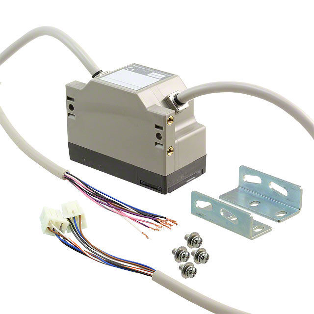
| 描述 | SENSOR 3M RANGE 10-31VDC NPN |
| 产品分类 | |
| 品牌 | Panasonic Industrial Automation Sales |
| 数据手册 | |
| 产品图片 |
|
| 产品型号 | PX-24ES |
| rohs | 无铅 / 符合限制有害物质指令(RoHS)规范要求 |
| 产品系列 | PX |
| 侵入防护 | IP65 |
| 光源 | 红外线 |
| 其它名称 | 1110-1378 |
| 响应时间 | 80ms |
| 工作温度 | -10°C ~ 55°C |
| 感应方法 | 反射 |
| 感应距离 | 118.1"(3m)9.8' |
| 标准包装 | 1 |
| 电压-电源 | 10 V ~ 31 V |
| 电缆长度 | 19.5"(50cm) |
| 调节类型 | 可调 |
| 输出配置 | NPN - 开路集电极 |
| 连接方法 | 线缆 |


- 商务部:美国ITC正式对集成电路等产品启动337调查
- 曝三星4nm工艺存在良率问题 高通将骁龙8 Gen1或转产台积电
- 太阳诱电将投资9.5亿元在常州建新厂生产MLCC 预计2023年完工
- 英特尔发布欧洲新工厂建设计划 深化IDM 2.0 战略
- 台积电先进制程称霸业界 有大客户加持明年业绩稳了
- 达到5530亿美元!SIA预计今年全球半导体销售额将创下新高
- 英特尔拟将自动驾驶子公司Mobileye上市 估值或超500亿美元
- 三星加码芯片和SET,合并消费电子和移动部门,撤换高东真等 CEO
- 三星电子宣布重大人事变动 还合并消费电子和移动部门
- 海关总署:前11个月进口集成电路产品价值2.52万亿元 增长14.8%


PDF Datasheet 数据手册内容提取
Long Range & Wide Area Photoelectric Sensor 899 PX-2 SERIES ■ General terms and conditions ...........F-17 ■ Sensor selection guide ..................P.831~ FIBER Related Information SENSORS ■ Glossary of terms........................P.1359~ ■ General precautions ......................P.1405 LASER SENSORS PHOTOELECTRIC SENSORS Conforming to MICRO EMC Directive PHOTOELECTRIC SENSORS AREA SENSORS LIGHT CURTAINS PRESSURE / FLOW SENSORS INDUCTIVE PROXIMITY SENSORS PARTICULAR USE SENSORS SENSOR OPTIONS SIMPLE WIRE-SAVING UNITS WIRE-SAVING SYSTEMS MEASUREMENT panasonic-electric-works.net/sunx SENSORS STATIC CONTROL DEVICES Compact size sensor realizes wide sensing ENDOSCOPE area & long sensing range LASER MARKERS PLC / TERMINALS Ideal sensing area with very little null zone HUMIANNT EMRAFCAHCINEES The advanced optical system of the PX-2 Aux(Oiliaprtyio sneanl)sor Auxiliary left OUT 1 area (700 mm 27.559 in) series reduces the null zones in front of an Adjacent left OUT 1 area ENERGY CONSUMPTION VISUALIZATION automatic guided vehicle (AGV). COMPONENTS The null zones at the sides are further FA COMPONENTS meainsiimly imzeodu inf taeudx wiliiathry c soennnseocrtso rws haicreh ucsaend b.e (O1a5 n UmmdT 31P 1.6X2 .a-842r10e3 4afEt : fS wt3 ,wi tmhit h P9 P.X8X-42-312 6ft) (O1a5 n UmmdT 31P 2.6X2 .a-842r10e3 4afEt : fS wt3 ,wi tmhit h P9 P.X8X-42-312 6ft) MACHINE VISION For PX-24, PX-24ES, PX-23ES SYSTEMS and PX-26 UV CURING Adjacent right OUT 1 area SYSTEMS Auxiliary sensor (Optional) Auxiliary right OUT 1 area (700 mm 27.559 in) Sensing areas selectable as per route condition Compact size for space-saving Selection Guide Sensing areas can be selected with Its size is half of a conventional model, Wafer Detection switches to suit the route conditions of and the attached cable 83 mm 3.268 in Liquid Leak an AGV. orientation is freely 62 mm Detection 2.441 in Further, in case of adjustable. Hence, it can Liquid Level Detection PX-24ES and PX-23ES, also fit in a small AGV. 43 mm Water Detection the sensing areas can Moreover, sensitivity 1.693 in Color Mark also be selected with adjustment can be done on Detection external signals. the front face. Hot Melt Glue Sensitivity adjuster Detection Ultrasonic Small / Long sensing range 5 m 16.404 ft type Sleep function Slim Object Detection Obstacle Detection PX-26 has a long sensing range of 5 m 16.404 ft. Even The sensor can be put into the sleep (stand-by) condition Other Products on a high-speed AGV, it can detect an object quite early when it is not used and can be restored to operating so that slowing down and stopping are smooth. condition by an external signal. Consequently battery is conserved as the power PX-2 Automatic interference prevention function consumption is reduced to 1/5. One PX-2 sensor can simultaneously receive beams from External sensitivity adjustment 25 Nos. of other PX-2 sensors without resulting in any interference. Even if AGVs are facing each other, the The sensitivity of the sensor can be adjusted, within the PX-2 sensor on one AGV reliably detects the other AGVs. range set by the manual adjuster, by an external input. Hence, it can be safely used even at a place where (For PX-24, PX-24ES, PX-23ES and PX-26) several AGVs are moving.
Long Range & Wide Area Photoelectric Sensor PX-2 SERIES 900 ORDER GUIDE FIBER SENSORS Main Sensor LSAESNESRORS PHOTO- ELECTRIC Type Appearance Sensing range Model No. SENSORS MICRO PHOTO- ELECTRIC SENSORS pe 3 m 9.843 ft PX-22 AREA y SENSORS d t Standar Short sensing range 1 m 3.281 ft PX-21 LCPFSLIREUGONERHWSSTSOTAURIRSNES / INDUCTIVE PROXIMITY SENSORS PX-24 PARTICULAR e USE p SENSORS nectable ty ol function 3 m 9.843 ft PX-24ES SOSIMEPPNTLSIEOONRS xiliary sensor con With external contr Short sensing range 1 m 3.281 ft PX-23ES WUWSMMSYNEIIEERRSINTANEETS--ESSTSSMOUAASVVRRIINNSEGG- u A g STATIC Long sensinrange 5 m 16.404 ft PX-26 CDOEVNITCREOSL ENDOSCOPE LASER MARKERS Auxiliary 700 mm 27.559 in PX-SB1 PLC / sensor TERMINALS HUMAN MACHINE INTERFACES ENERGY CONSUMPTION Accessories VISUALIZATION COMPONENTS • MS-PX-2 (Main sensor mounting bracket) • MS-NX5-1 (Auxiliary sensor mounting bracket) FA COMPONENTS MACHINE VISION SYSTEMS UV CURING SYSTEMS Two bracket set Two M4 (length 25 mm Four M4 (length 8 mm 0.984 in) screws with 0.315 in) screws with washers and two M4 nuts washers are attached. are attached. Selection Guide Wafer Detection OPTIONS Liquid Leak Detection Liquid Level Detection Auxiliary sensor mounting bracket Water Detection Designation Model No. Description • MS-NX5-2 • MS-NX5-3 CDoeltoerc tMioanrk Hot Melt Glue Auxiliary sensor MS-NX5-2 Foot biangled mounting bracket (Sensor protection bracket) Detection mounting Ultrasonic bracket MS-NX5-3 Back angled mounting bracket Small / Slim Object Detection Obstacle Detection Other Two M4 (length 25 mm Two M4 (length 25 mm Products 0.984 in) screws with 0.984 in) screws with washers and two M4 nuts washers and two M4 nuts are attached. are attached. PX-2
901 Long Range & Wide Area Photoelectric Sensor PX-2 SERIES SPECIFICATIONS FIBER SENSORS LASER SENSORS Main sensors PHOTO- Auxiliary sensor connectable model ELECTRIC SENSORS Standard model MICRO Type With external control function Long sensing PHOTO- ELECTRIC Short sensing range Short sensing range range SENSORS AREA Item Model No. PX-22 PX-21 PX-24 PX-24ES PX-23ES PX-26 SENSORS Sensing range (OUT 1 and OUT 2 areas) (Note 2) 3 m 9.843 ft 1 m 3.281 ft 3 m 9.843 ft 1 m 3.281 ft 5 m 16.404 ft LIGHT CURTAINS Hysteresis (Note 2) 15 % or less of operation distance PRESSURE / Supply voltage 10 to 31 V DC including ripple FLOW SENSORS Power consumption (Note 3) Under operation: 1.5 W or less, Under sleep condition: 0.3 W or less (without auxiliary sensor) INDUCTIVE PROXIMITY OUT1 SENSORS OR circuit among the effective center, NPN open-collector transistor PARTICULAR left, right, adjacent left / right OUT 1 areas • Maximum sink current: 100 mA SENSOURSES and the effective auxiliary left / right areas • Applied voltage: 40 V DC or less (between OUT 1 / OUT 2 and 0 V) OUT2 • Residual voltage: 1.5 V or less (at 100 mA sink current) SENSOR OR circuit among the effective center, left 0.4 V or less (at 16 mA sink current) OPTIONS and right OUT 2 areas SIMPLE WIRE-SAVING Utilization category DC-12 or DC-13 UNITS Output operation Selectable either Light-ON or Dark-ON with a switch (Output operation of OUT 1 and OUT 2 is the same.) WIRE-SAVING SYSTEMS Short-circuit protection Incorporated MEASURE- MENT NPN open-collector transistor SENSORS • Maximum sink current: 100 mA Extraneous light monitor STATIC – • Applied voltage: 40 V DC or less (between extraneous light monitor output and 0 V) CDOENVTIRCOESL output • Residual voltage: 1.5 V or less (at 100 mA sink current) 0.4 V or less (at 16 mA sink current) ENDOSCOPE Output operation – ON when modulated beam other than its own (including auxiliary sensor’s) light is received LASER Short-circuit protection – – MARKERS Response time 80 ms or less PLC / TERMINALS OUT 1 area Red LED (lights up when the beam is received in the effective OUT 1 areas) Operation HUMAN indicators MACHINE OUT 2 area Yellow LED (lights up when the beam is received in the effective OUT 2 areas) INTERFACES ENERGY Sensitivity adjuster Continuously variable adjusters (OUT 1, adjacent right OUT 1, adjacent left OUT 1 and OUT 2 areas are adjusted independently.) CONSUMPTION VCISOUMAPLOIZNAETNIOTNS External sensitivity adjustment function – Sensitivity adjustment is possible with an analog input. FA Four sensing areas are selectable with dip switches, and COMPONENTS Sensing area Four sensing areas are selectable with dip switches. Fixed eight sensing areas are selectable with external inputs. MACHINE VISION Sleep function Operating / sleep selectable with external input SYSTEMS UV Automatic interference prevention function Optical interference from up to 25 units is prevented. CURING SYSTEMS Pollution degree 3 (Industrial environment) Protection IP65 (IEC) ce Ambient temperature –10 to +55 °C +14 to +131 °F (No dew condensation or icing allowed), Storage: –20 to +70 °C –4 to +158 °F Selection an Guide st Ambient humidity 35 to 85 % RH, Storage: 35 to 85 % RH DLieqDtueeWidtce aLctietfoieoannkr ental resi AEmMbCient illuminance Incandescent light: 3E,N00 600 ℓ9x4 a7t- 5th-2e light-receiving face Liquid Level m Detection n o Voltage withstandability 1,000 V AC for one min. between all supply terminals connected together and enclosure CDoeloteWr cMatiatoernkr Envir Insulation resistance 20 MΩ, or more, with 500 V DC megger between all supply terminals connected together and enclosure Detection Vibration resistance 10 to 500 Hz frequency, 3 mm 0.118 in amplitude (20 G max.) in X, Y and Z directions for two hours each Hot Melt Glue Detection Shock resistance 500 m/s2 acceleration (50 G approx.) in X, Y and Z directions for three times each Ultrasonic Small / Slim Emitting element Infrared LED (Peak emission wavelength: 950 nm 0.037 mil, modulated) Object Detection Obstacle Material Enclosure: ABS, Lens: Acrylic, Cover: Polycarbonate Detection Other 0.3 mm2 5-core cabtyre cable, 0.5 m For input and output: 0.18 mm2 9-core (PX-24ES and PX-23ES: 12-core) cabtyre cable, 0.5 m 1.640 ft long Products Cable 1.640 ft long (for input and output) For auxiliary sensor connection: 0.18 mm2 10-core connector attached cabtyre cable, 0.5 m 1.640 ft long Cable extension Extension up to total 100 m 328.084 ft (10 m 32.808 ft for auxiliary sensor connection) is possible with 0.3 mm2, or more, cable. PX-2 Net weight: 210 g approx. Net weight: 220 g approx. Net weight: 210 g approx. Weight Gross weight: 390 g approx. Gross weight: 400 g approx. Gross weight: 390 g approx. Accessories MS-PX-2 (Main sensor mounting bracket): 1 set, Adjusting screwdriver: 1 pc., Matrix chart for sensing areas and external inputs: 1 sheet (PX-24ES and PX-23ES only) Notes: 1) Where measurement conditions have not been specified precisely, the conditions used were an ambient temperature of +23 °C +73.4 °F. 2) The sensing range is specified for white non-glossy paper (300 × 300 mm 11.811 × 11.811 in) as the object. 3) Obtain the current consumption by the following calculation. Current consumption = Power consumption ÷ Supply voltage (e.g.) When the supply voltage is 12 V, the current consumption (operating condition) is: 1.5 W ÷ 12 V = 0.125 A = 125 mA
Long Range & Wide Area Photoelectric Sensor PX-2 SERIES 902 SPECIFICATIONS FIBER SENSORS LASER Auxiliary sensor (Note 2) SENSORS Model No. PHOTO- PX-SB1 ELECTRIC Item SENSORS MICRO Applicable main sensor PX-24, PX-24ES, PX-23ES or PX-26 PHOTO- ELECTRIC SENSORS Connectable units Up to two PX-SB1’s can be connected to one main sensor. AREA Sensing range (Note 3) 700 mm 27.559 in SENSORS Supply voltage Supplied from the main sensor LIGHT CURTAINS Current consumption Current consumption of the main sensor increases by 30 mA approx. per auxiliary sensor. Output OR circuit with the main sensor’s OUT 1 PFLROEWSSURE / SENSORS Operation indicator Red LED (lights up when the beam is received) INDUCTIVE Sensitivity adjuster Continuously variable adjuster PSRENOSXOIMRITSY Emitting element Infrared LED (modulated) PARTICULAR USE Material Polycarbonate SENSORS Cable 0.3 mm2 5-core cabtyre cable, 2 m 6.562 ft long SENSOR OPTIONS Cable extension Extension up to total 10 m 32.808 ft is possible with 0.3 mm2, or more, cable. SIMPLE Weight Net weight: 130 g approx., Gross weight: 240 g approx WUNIRITES-SAVING Accessories MS-NX5-1 (Auxiliary sensor mounting bracket): 1 set, Adjusting screwdriver: 1 pc. WIRE-SAVING SYSTEMS Specifications other than the above are identical with the main sensor. MEASURE- MENT Notes: 1) Where measurement conditions have not been specified precisely, the conditions used were an ambient temperature of +20 °C +68 °F. SENSORS 2) The auxiliary sensor cannot be used as a stand-alone unit. STATIC 3) The sensing range is specified for white non-glossy paper (300 × 300 mm 11.811 × 11.811 in) as the object. CONTROL DEVICES ENDOSCOPE I/O CIRCUIT AND WIRING DIAGRAMS LASER MARKERS PX-24ES PX-23ES PLC / TERMINALS I/O circuit diagram Wiring diagram Brown HUMAN Color code For auxiliary Load MACHINE D (Brown) +V sensor connection Black Load IENNTEERRGFY ACES CONSUMPTION Load Load VISUALIZATION Tr1 (Bla1c0k0) mOUA Tm 1ax. Load White +– 10 to 31 V DC CFAO MPONENTS Load COMPONENTS ZD1 (White) OUT 2 + Black / White Tr2 – 10 to 31 V DC MACHINE 100 mA max. VISION ZD2 (Black / White) Extraneous light monitor output Blue SYSTEMS Tr3 100 mA max. *1 UCVU RING ZD3 (Blue) 0 V Pink SYSTEMS uit (Pink) *1 or circ A(Preinak S/ eBlleacctkio) n Input 1 Pink / Black ens Area Selection Input 2 Selection S (Pink / White) Pink / White Guide Area Selection Input 3 Wafer Detection (Violet) Auxiliary right OUT 1 Violet Liquid Leak area ineffective input Detection Liquid Level (Violet / Black) Auxiliary left Detection OUT 1 area ineffective input Violet / Black Water Detection (Pink / Violet) Sleep input Pink / Violet CDoeltoerc tMioanrk (Pink / Gray) External 6 mA max. Hot Melt Glue sensitivity adjustment input Detection (Input impedance: 1 kΩ approx.) + – Pink / Gray Ultrasonic 0 to +5 V DC + – Internal circuit Users’ circuit * 1 0 to +5 V DC SOmbjaelcl t/ DSelimte ction Obstacle Non-voltage contact or NPN open-collector transistor Detection Other Symbols … D: Reverse supply polarity protection diode Products ZD1, ZD2, ZD3: Surge absorption zener diode or Tr1, Tr2, Tr3 : NPN output transistor PX-2 • Area selection input Low (0 to 1 V): Depends on the logic combination High (4.5 to 31 V, or open): Depends on the logic combination • Auxiliary area ineffective input Low (0 to 1 V): Area ineffective High (4.5 to 31 V, or open): Area effective • Sleep input Low (0 to 1 V): Sleep condition High [(supply voltage – 1 V) to 31 V, or open]: Operating condition
903 Long Range & Wide Area Photoelectric Sensor PX-2 SERIES I/O CIRCUIT AND WIRING DIAGRAMS FIBER SENSORS LASER SENSORS PX-22 PX-21 PHOTO- I/O circuit diagram Wiring diagram ELECTRIC SENSORS MICRO Color code PHOTO- ESLEENCSTORRICS D (Brown) +V Brown AREA Load Load SENSORS (Black) OUT1 Black PCRUSERESNTLSFSIAUGLOIRONHREWSTS / Sensor circuit Tr2Tr1 ZDZ2D1 ((WBluh1eit0e) 0)0 O mVUAT m2a1x0.0 mA maLxo.ad +– 10 to 31 V DC WBluheite Load +– 10 to 31 V DC PINSRDEOUNXCSIMTOIIRVTESY (Pink / Violet) Sleep input*1 Pink / Violet *1 PARTICULAR USE SENSORS Internal circuit Users’ circuit * 1 SENSOR OPTIONS Non-voltage contact or NPN open-collector transistor Symbols … D: Reverse supply polarity protection diode SIMPLE ZD1, ZD2: Surge absorption zener diode WIRE-SAUVNIINTGS Tr1, Tr2 : NPN output transistor or WIRE-SAVING • Sleep input SYSTEMS Low (0 to 1 V): Sleep condition High [(supply voltage – 1 V) to 31 V, or open]: Operating condition MEASURE- MENT SENSORS STATIC CONTROL DEVICES ENDOSCOPE PX-24 PX-26 I/O circuit diagram Wiring diagram LASER MARKERS Color code For auxiliary D (Brown) +V sensor connection PLC / TERMINALS Brown Load MAHCUHMIANNE Tr1 (Black) OUT 1 Load Load CINOTNESRUEFMNAPECTRIEOGSNY Tr2 ZD1 (Wh1it0e0) mOUA Tm 2ax. Load +– 10 to 31 V DC Black Load Load VISUALIZATION 100 mA max. White + CMCOOMAMPCPOOHNNEEINNNFTTEASS or circuit Tr3 ZDZ3D2 ((BBlalcuke / )W 0hi tVe) Extraneous lig1ht0 m0o nmitoAr omutpauxt. Black / White – 10 to 31 V DC SYSVTISEIOMNS Sens O(VUioTle 1t )a Areuax iilniaerfyfe rcitgivhet input*1 Blue UV *1 SYCSUTREINMGS (OVUioTle 1t /a Brelaac ikn)e Affeucxtiliivaer yin lepfut t Violet (Pink / Violet) Sleep input Violet / Black (Pink / Gray) SeleGcutiiodne Eadxjtuesrntmale snet ninspituivtity 6 mA max. Pink / Violet Wafer (Input impedance: 1 kΩ approx.) + – Detection 0 to +5 V DC Liquid Leak Internal circuit Users’ circuit Pink / Gray Detection + – Liquid Level 0 to +5 V DC Detection * 1 DeteWcatitoenr Symbols … D: Reverse supply polarity protection diode Color Mark ZD1, ZD2, ZD3: Surge absorption zener diode Non-voltage contact or NPN open-collector transistor Detection Tr1, Tr2, Tr3 : NPN output transistor Hot Melt Glue or Detection Ultrasonic • Auxiliary area ineffective input Small / Slim Low (0 to 1 V): Area ineffective Object Detection High (4.5 to 31 V, or open): Area effective Obstacle Detection • Sleep input Other Low (0 to 1 V): Sleep condition Products High [(supply voltage – 1 V) to 31 V, or open]: Operating condition PX-2
Long Range & Wide Area Photoelectric Sensor PX-2 SERIES 904 SENSING CHARACTERISTICS (TYPICAL) FIBER SENSORS How to read sensing characteristics LSAESNESRORS • Sensing field Sensing area • Correlation between external sensitivity PHOTO- ELECTRIC adjustment input voltage and sensing range SENSORS 1310.08 1×1 3 ×0 01 1m.8m11 in CL.. :: CLeefnt taerre aarea L’. L. 300 × 300 mm It shows the variation MPHICORTOO- Non-glossy paper R. : Right area C. W11h.8it1e1 n ×o n1-1g.l8o1ss1y i npaper in the sensing range ESLEENCSTORRICS L’. : Adjacent left OUT 1 area when the external ℓ ℓ R’. : Adjacent right OUT 1 area R’. R. input voltage is ASRENEASORS L L changed from 0 to Sensing object +5 V with the LIGHT L CURTAINS sensitivity adjuster set at the maximum PRESSURE / FLOW Type of non-glossy paper sensing range. SENSORS Horizontal Vertical (up-down) direction (left-right) direction INDUCTIVE PROXIMITY Note: The sensitivity has been adjusted so that White non-glossy paper (lightness: 9) SENSORS the maximum sensing range for white Gray non-glossy paper (lightness: 5) • Correlation between sensitivity adjuster and sensing range PARTICULAR non-glossy paper (300 × 300 mm 11.811 × Please note that due to the adjuster’s characteristics it may USESNE SORS 11.811 in) is 3 m 9.843 ft (1 m 3.281 ft for Black non-glossy paper (lightness: 2) be difficult to adjust the sensitivity at a close distance or near PX-21 and PX-23ES, 5 m 16.404 ft for SENSOR PX-26) with the L., C. and R. areas effective. to rated sensing distances. (Refer to “Correlation between OPTIONS sensitivity adjustor and sensing range” below.) SIMPLE WIRE-SAVING UNITS All models WIRE-SAVING SYSTEMS Correlation between setting distance and excess gain MEASURE- MENT 100 SENSORS STATIC 50 CDOEVNITCREOSL n ENDOSCOPE ai PX-26 g Excess 105 PPXX--2224 EPSX-24 LMAASREKRERS PX-SB1 PLC / TERMINALS PX-21 PX-23ES HUMAN 1 MACHINE 0 1 2 3 4 5 INTERFACES 3.281 6.562 9.843 13.123 16.404 ENERGY Setting distance L (m ft) CONSUMPTION VISUALIZATION COMPONENTS PX-22 PX-24 PX-24ES FCAO MPONENTS Correlation between external sensitivity Sensing fields adjustment input voltage and sensing range MVIASCIOHNIN E SYSTEMS • All areas effective (Horizontal) • C. area effective (Horizontal) • All areas effective (Vertical) (Excluding PX-22) UV 4 4 4 4 CSYUSRTINEGM S 13.123 Gglorassyy n poanp-er Wglohsistey pnaopne-r Bglolascsyk pnaopne-r 13.123 13.123 13.123 Max. sensing range: 3 m 9.843 ft nce L (m ft)9.82343 nce L (m ft)9.84233 Wglohsitsey n poanp-er nce L (m ft)9.82343 Wglohsitsey n poanp-er ge L (m ft)9.82343 Max. sensing range: 2 m 6.562 ft SGeuliedcetion Setting dista36..2518612 Setting dista36..2586112 Gglroasys yn opna-per Setting dista36..2518612 Gglroasys yn opna-per Sensing ran36..2518612 Max. sensing range: 1 m 3.281 ft WDLDLDiieeqqeattuueetiifedcdcett ciiLLroot eennioavekn l Water 0 0 0 Detection 1 0.5 0 0.5 1 1 0.5 0 0.5 1 1 0.5 0 0.5 1 0 1 2 3 4 5 Color Mark 3.281 1.640 1.640 3.281 3.281 1.640 1.640 3.281 3.281 1.640 1.640 3.281 External sensitivity adjustment Detection Left Center Right Left Center Right Down Center Up input voltage (V) Hot Melt Glue Operating point ℓ (m ft) Operating point ℓ (m ft) Operating point ℓ (m ft) Detection Ultrasonic Correlation between sensitivity adjuster and sensing range Small / Slim Object Detection • OUT1(OUT2) area • Adjacent right (left) OUT1 area Obstacle Detection 4 2 Other 13.123 3W00h i×t e3 0n0o mnm-g 1l1o.s81s1y × p 1a1p.8e11r ft 6.562 3W00h i×te 3 0n0o nm-mg l1o1s.8s1y1 p× a11p.e81r1 ft Products L (m ft) 9.8343 L 2 3 4 L (m ft) 14.9.252 L 45° 45° Ma(lesdfeatja amOcseeUu nraTets1 mr tiagherhenet ta a Om)d UjeatTch1eo ndat r oefa t he 2 3 4 PX-2 e e ng 2 1 5 ng 1 1 5 ng ra6.562 Cmeenatseur raermeean t method 0 6 ng ra3.281 0 6 ensi 1 Adjuster scale ensi0.5 Adjuster scale S3.281 S1.640 0 2 4 6 0 2 4 6 (Min.) Adjuster scale (Max.) (Min.) Adjuster scale (Max.)
905 Long Range & Wide Area Photoelectric Sensor PX-2 SERIES SENSING CHARACTERISTICS (TYPICAL) FIBER SENSORS LASER SENSORS PX-21 PX-23ES PHOTO- Correlation between external sensitivity ELECTRIC Sensing fields SENSORS adjustment input voltage and sensing range MICRO • All areas effective (Horizontal) • C. area effective (Horizontal) • All areas effective (Vertical) (PX-23ES only) PHOTO- ELECTRIC SENSORS PPCISNRSRUESDEEORENUSNXNTLSSCASIFSIAUMOGTROLOIRIOINREHRVTREWSASESYTS / Setting distance L (m ft)013..62.485101 WgGgBgllllorooahasssciytssske yyyn nn opppoonaaann-ppp--eeerrr Setting distance L (m ft)013...62541801 WgGgllorohassiytsse yyn n opponaan-pp-eerr Setting distance L (m ft)013..62.485101 GgWgllroohassiytsse yyn n opponaan-pp-eerr Sensing range L (m ft)013...62541801 MMaxa.x s. esnesnisnign gra rnagneg:e 0: .15 mm 31..268410 fftt PARTICULAR USE 0 0 0 SENSORS 400 200 0 200 400 400 200 0 200 400 400 200 0 200 400 0 1 2 3 4 5 15.748 7.874 7.874 15.748 15.748 7.874 7.874 15.748 15.748 7.874 7.874 15.748 External sensitivity adjustment SENSOR Left Center Right Left Center Right Down Center Up input voltage (V) OPTIONS Operating point ℓ (mm in) Operating point ℓ (mm in) Operating point ℓ (mm in) SIMPLE WIRE-SAUVNIINTGS Correlation between sensitivity adjuster and sensing range • OUT1 (OUT2) area • Adjacent right (left) OUT1 area WIRE-SAVING SYSTEMS 400 MEASURE- 300 × 300 mm 11.811 × 11.811 in 15.748 MENT White non-glossy paper EMCNSDOADEESRONNLVTSAKTSIACSERCOOTEROERPIRCSSSLE Sensing range L (m ft) 031..26.814510 CmL eenatseur raermeean t method A10d 2 j uste3r sc4a6l 5e Sensing range L (mm in) 1123137...000898137000174 MLe a4su5r°e me4n5t °m31Wg 1e0lo.th80hs1io ts1×de y × o3n fp10 ot1ah0n.e8p - m1e1rm in A10d 2 j uste3r sca46l 5e adjacent right OUT1 area (same PLC / as the adjacent left OUT1 area) TERMINALS 0 2 4 6 0 2 4 6 (Min.) Adjuster scale (Max.) (Min.) Adjuster scale (Max.) HUMAN MACHINE INTERFACES ENERGY CONSUMPTION PX-26 VISUALIZATION COMPONENTS Sensing fields FA Correlation between external sensitivity COMPONENTS • Horizontal [All areas effective (Note)] • Vertical [All areas effective (Note)] adjustment input voltage and sensing range MACHINE VISION 8 8 8 SYSTEMS 26.247 26.247 26.247 Max. sensing range: 4 m 13.123 ft UV SDSYCeeStlUeeGWTRccEuattIiiiNMfoodeGSnner Setting distance L (m ft)11639...516628246235 WgGgBgllllorooahasssciytssske yyyn nn opppoonaaann-ppp--eeerrr Setting distance L (m ft)11639...516628246235 WgGgllorohassitysse yy nn popoananp-p-eerr Sensing range L (m ft)11639...516262846235 M3 amx .9 s.8e4n3s ifntg rangeMM:aaxx.. sseennssiinnM5gg amrraax nn.1 ggs6eee.4::n 021s4i nmm fgt 63ra..52n68g21e :fftt Liquid Leak Detection 0 0 LiqDueidt eLcetivoenl 3.2181 10.6.540 0 10.6.540 3.2181 3.2181 10.6.540 0 10.6.540 3.2181 0 Exte1rnal sen2sitivity a3djustm4ent 5 Left Center Right Down Center Up input voltage (V) Water Detection Operating point ℓ (m ft) Operating point ℓ (m ft) Color Mark Note: Area selection is not possible. Detection Hot Melt Glue Correlation between sensitivity adjuster and sensing range Detection Ultrasonic • OUT1 (OUT2) area • Adjacent right (left) OUT1 area ObjecStm Daellt e/ cStiloimn 8 2 26.247 6.562 300 × 300 mm 11.811 × 11.811 in Obstacle 300 × 300 mm 11.811 × 11.811 in White non-glossy paper PDreotOdecuthtcioetsnr L (m ft) 19.6685 L White non-glossy paper 2 3 4 L (m ft) 41.9.252 L 45° 45° Ma(lesdfeatja amOcseeUu nraTets1 mr tiagherhenet ta a Om)d UjeatTch1eo ndat r oefa t he 2 3 4 e e PX-2 ng rang13.1423 Cmeenatseur raermeean t method 10 65 ng rang3.2181 10 65 ensi 2 Adjuster scale ensi0.5 Adjuster scale S6.562 S1.640 0 2 4 6 0 2 4 6 (Min.) Adjuster scale (Max.) (Min.) Adjuster scale (Max.)
Long Range & Wide Area Photoelectric Sensor PX-2 SERIES 906 SENSING CHARACTERISTICS (TYPICAL) FIBER SENSORS LASER PX-SB1 SENSORS PHOTO- Sensing field ELECTRIC SENSORS • Horizontal and vertical directions MICRO PHOTO- ELECTRIC 0.8 SENSORS 2.625 AREA SENSORS m ft)01.9.669 White non- L ( glossy paper LCIUGRHTTAINS e distanc01.3.142 PFSLREONEWSSSOURRSE / g Settin00.6.526 IPSNREDNOUSXCOIMTRIIVTSEY PARTICULAR 0 USE 40 20 0 20 40 SENSORS 1.575 0.787 0.787 1.575 (Down) Left Center Right (Up) SENSOR Operating point ℓ (mm in) OPTIONS SIMPLE PRECAUTIONS FOR PROPER USE Refer to General precautions. WUNIRITES-SAVING WIRE-SAVING SYSTEMS All models MEASURE- MENT CAUTION SENSORS • Never use this product as a sensing device STATIC for personnel protection. • Periodical maintenance check CDOEVNITCREOSL • In case of using sensing devices for The person in charge must periodically confirm the performance personnel protection, use products which of the product and maintain a record of such checks. In addition, ENDOSCOPE meet laws and standards, such as OSHA, whenever the operating environment of the product is changed due ANSI or IEC etc., for personnel protection to system modification, etc., performance check must be done. LMAASREKRERS applicable in each region or country. Mounting PLC / TERMINALS Hazard Indications • The tightening torque for the main sensor should be 1.2 N·m or less. HUMAN MACHINE INTERFACES In this catalog, WARNING and CAUTION are ENERGY indicated depending upon the level of danger. Please CONSUMPTION VISUALIZATION observe them strictly for the safe use of this sensor. M4 (length 8 mm COMPONENTS 0.315 in) WARNING swcarsehwe wrsith Smeonusnotirng FCAO MPONENTS ‘WARNING’ indicates a potentially hazardous situation bracket MACHINE that, if not avoided, could result in death or serious injury. M(ASc-cPeXss-2ory) VSIYSSIOTENM S UV CAUTION CURING SYSTEMS ‘CAUTION’ indicates a hazardous situation that, if not avoided, may result in minor or moderate injury. Further, they also indicate the condition of risk of physical damage to machinery. • The tightening torque for PX-SB1 (auxiliary sensor) Selection should be 0.8 N·m or less. Guide Wafer Detection WARNING Liquid Leak M4 nuts M4 (length 25 mm Detection • Installation of a touch bumper 0.984 in) Liquid Level screw with washers Detection You are requested to always install a touch bumper when this Water product is used on an automatic guided vehicle (AGV). Detection Sensor mounting Color Mark bracket Detection CAUTION MS-NX5-1 Hot Melt Glue (Accessory) Detection • Use outside Japan Ultrasonic Small / Slim This sensor conforms to the EMC Directive. However, it is not Object Detection certified by a competent body in accordance with other country Obstacle Detection safety standards. Since each country has its regulations, please Other follow the local and national regulations of the country where this Products sensor is used. • Mount the sensor, horizontally, at least 300 mm 11.811 in CAUTION above the floor, to avoid reflection from the floor. PX-2 • Fail-safe measures This sensor is meant for proximity detection and does not possess control functions for safety maintenance. If fail-safe measures are required, consider their incorporation in the total system. 300 mm 11.811 in or more Further, do not connect the sensor output directly to a stopping mechanism (brake).
907 Long Range & Wide Area Photoelectric Sensor PX-2 SERIES PRECAUTIONS FOR PROPER USE FIBER Refer to General precautions. SENSORS Others LASER All models SENSORS • Do not use during the initial transient time (0.7 sec.) after Automatic interference prevention function PHOTO- the power supply is switched on. ELECTRIC SENSORS • In case several sensors are used at the same place, take • Take care that an initial rush current (1.5 A approx. at PMHIOCTROO- care that the number of sensors from which beams may 10 V DC and 5 A approx. at 31 V DC) will flow when the ESLEENCSTORRICS be simultaneously incident is 25 sensors or less. power supply is switched on. AREA SENSORS PX-22 PX-21 PX-24 PX-24ES PX-23ES LIGHT CURTAINS Selection of sensing area PRESSURE / FLOW Setting method Internal Area selection input (Note) INT. SENSORS Total of 26 sensors INDUCTIVE can be used at seINTt.tings (PX-24ES and PX-23ES only) EXT. PSREONXSIMOIRTSY the same place. Sensing area Input 1 Input 2 Input 3 EXT. PARTICULAR All areas ineffective USE SENSORS Simultaneously incident beam SENSOR from up to 25 sensors. ― L L L OPTIONS Sleep function (Incorporated in all models) SIMPLE WIRE-SAVING • When the sleep input is made Low, the sensor goes into the sleep state UNITS and the operation can be stopped. Power consumption during the sleep Center area effective WIRE-SAVING state is 0.3W max. (Without auxiliary sensors). SYSTEMS Notes: 1) Response time of the sleep input is 50ms. ― H L L MEASMUERNET- 2) Reactivation from the sleep state to the operation state takes SENSORS 0.7 sec. approx. Operation during this transient state should be STATIC avoided. CDOENVTIRCOESL 3) When the sleep function is not used, keep the sleep input wire Center, right and adjacent right open or insulated and prevent contact with other wires. OUT 1 areas effective ENDOSCOPE ⑨ ⑧ Part description ― L H L ⑩ ⑦ LASER MARKERS PLC / TERMINALS Center left and adjacent left HUMAN OUT 1 areas effective MACHINE INTERFACES ENERGY CONSUMPTION ⑤ ⑥ ― H H L VISUALIZATION COMPONENTS ③ ④ ① ② FA COMPONENTS MACHINE Sign Item Description Center and left / right adjacent VISION SYSTEMS OUT 1 areas effective UV OUT 2 area Lights up when the beam is received in the R L CURING SYSTEMS Operation (Yellow LED) OUT 2 area. L L H indicator OUT 1 area Lights up when the beam is received in the OFF (Red LED) OUT 1 area. OUT 2 area Sensing area sensitivity adjuster. Selection Adjacent left OUT 1 area Center, right and adjacent left / right Guide OUT 1 area OUT 1 area OUT 1 areas effective Wafer Detection Sensitivity Adjacent right R L LiqDueidte Lcetioank adjuster OUT 1 area Adjacent OrigUhTt 2O UarTe a1 area H L H LiqDueidt eLcetivoenl Adjacent left OFF Water OUT 1 area Detection Color Mark Selection of main sensor sensing areas. (OUT 1,OUT 2 ) Detection Sensing Left area Left area RL Center, left and adjacent left / right Hot Melt Glue area Effective OUT 1 areas effective Detection selection center OFF R L Ultrasonic switch area RL Small / Slim (Note 1) Right area Ineffective L H H Object Detection Right area OFF OFF DOebtestcaticolen Select the operation D.ON Light-ON Other mode for OUT 1 Products Oseuletpcutito onp sewraittciohn mode and OUT 2 with the DL..OONN All areas effective operation mode Dark-ON PX-2 selection switch. L.ON R L H H H Select whether to INT. perform selection of Dipswitches OFF External control function sensing area with EXT. selection switch (Note 2) INT. the dipswitch or by L: Low (0 to 1V), H: High (4.5 to 31V, or open) External inputs external input. EXT. Note: Response time of area the selection input is 80 ms. Notes: 1) Not incorporated in PX-26. 2) Incorporated in PX-24ES and PX-23ES.
Long Range & Wide Area Photoelectric Sensor PX-2 SERIES 908 PRECAUTIONS FOR PROPER USE Refer to General precautions. FIBER SENSORS PX-24 PX-24ES PX-23ES PX-26 LASER SENSORS External sensitivity adjustment function Extraneous light monitor function PHOTO- ELECTRIC (Not incorporated in PX-22 and PX-21) SENSORS • The sensitivity can be adjusted, within the range set by MICRO the manual sensitivity adjuster, by an analog voltage (0 to • If the sensor receives modulated light other than its own PHOTO- ELECTRIC +5 V) applied to the external sensitivity adjustment input. (including auxiliary sensor’s) light, the extraneous light SENSORS The sensitivity varies with the magnitude of the applied monitor output turns ON. The operation of the extraneous AREA SENSORS voltage. light monitor output has absolutely no affect on sensing. Notes: 1) The sensitivity of the auxiliary sensor is not changed. It is useful for recognizing presence of other sensors near LIGHT CURTAINS 2) Sensitivity adjustment beyond the range set by the manual this sensor in case of intersecting AGV paths, etc. sensitivity adjuster is not possible. PRESSURE / FLOW SENSORS Input voltage 0 V +5 V or open INDUCTIVE PROXIMITY SENSORS Minimum Maximum Sensitivity Maximum sensitivity set by the PUASRET ICULAR manual sensitivity adjuster SENSORS Note: The extraneous light monitor output is not incorporated with a SENSOR 3) This wire should be insulated if it is not used. short-circuit protection circuit. Do not connect it directly to a power OPTIONS supply or a capacitive load. SIMPLE WIRE-SAVING UNITS PX-SB1 WIRE-SAVING SYSTEMS Sensitivity setting MEASURE- • This sensor must always be used with the applicable MENT SENSORS main sensor. This sensor does not work as a standalone • Sensitivity adjustment of PX-SB1 is performed with the STATIC unit. (It cannot be used with PX-22 or PX-21.) emitter volume. If sensitivity cannot be set to close range CONTROL DEVICES even after adjusting the emitter volume, then an aux sensor might be receiving the light from the main sensor. ENDOSCOPE Selection of auxiliary area If that is the case, adjust sensitivity with the emitter • Aux area can be selected by aux area ineffective input of volume and the receiver volume. For details, see the LASER MARKERS the main sensor. instruction manual that comes with the product. PLC / Connection with the main sensor TERMINALS Ineffective input Auxiliary left Auxiliary right Sensing area OUT 1 area OUT 1 area HMUAMCHANIN E INTERFACES Spiral lead wire Auxiliary left / right OUT 1 ENERGY CONSUMPTION area ineffective VISUALIZATION COMPONENTS Left aux sensor FA L L COMPONENTS Main sensor MACHINE VISION SYSTEMS UV Auxiliary left OUT 1 area Right aux sensor CSYUSRTINEGM S effective • Connect the main sensor connector attached cable to the aux sensor connector attached cable. H L • The spiral lead wire side of the main sensor connector Selection attached cable is the left aux sensor side. Guide Wafer Detection Liquid Leak Auxiliary right OUT 1 area Detection effective Liquid Level Detection Water Detection L H Color Mark Detection Hot Melt Glue Detection Ultrasonic Auxiliary left / right OUT 1 Small / Slim Object Detection area effective Obstacle Detection H H OPrtohdeur cts PX-2 L: Low (0 to 1 V), H: High (4.5 to 31 V or open) Note: Aux area disable input has nothing to do with the external control function selection switch of the main sensor.
909 Long Range & Wide Area Photoelectric Sensor PX-2 SERIES FIBER SENSORS DIMENSIONS (Unit: mm in) The CAD data in the dimensions can be downloaded from our website. LASER SENSORS PX-2□ Main sensor PHOTO- ELECTRIC SENSORS (ø10)(ø0.394) MICRO 2-ø4.6 ø0.181 mounting holes PHOTO- ELECTRIC 45° SENSORS AREA SENSORS ø6.7 ø0.264 cable, 0.5 m 1.640 ft long (Note) (for auxiliary sensor connection; ) CURTLIAGINHST 3.82368 26.438027.8374 with connector at the end PRESSURE / 41.5 FLOW 1.634 SENSORS 22 INDUCTIVE 0.866 PPSARREOTNXICSIMUOLIRTASYR 4.5 01.4272 Cseennsteinrg of 13.85.156 45° ø6.7 ø0.264 cable, 0.5 m 1.640 ft long USE 0.177 (for input and output) SENSORS OSPETNISOONRS 1.46393((14.059.54)) 21.5 0.1597 23.5 SIMPLE 11 0.433 0.846 0.925 WIRE-SAVING UNITS 2.5 WIRE-SAVING 0.098 9 OUT 1 area operation indicator (Red) 28.5 20 SYSTEMS 0.354 15 OUT 2 area operation indicator (Yellow) 1.122 602.787 4-M4 threads, 4 deep 0.591 2.441 MEASURE- MENT SENSORS Note: PX-22 and PX-21 do not have this cable. STATIC CONTROL DEVICES ENDOSCOPE LASER MARKERS PX-SB1 Auxiliary sensor PLC / TERMINALS Receiving adjuster (incorporated) HUMAN MACHINE 11 INTERFACES 0.433 ENERGY CONSUMPTION 18 VCISOUMAPLOIZNAETNIOTNS 0.709 Operation 1.5 35 indicator (Red) 0.059 1.378 FA COMPONENTS 6 0.236 20.5 Beam-receiving MAVCISHIIONNE 0.807 part SYSTEMS 40.5 1.594 Beam-emitting SYCSUTREINMUGVS Cseennsteinrg of part 2.64241 1.59069 Sensitivity Emission adjuster adjuster cap (incorporated) SeleGcutiiodne 1 2-ø4.5 ø0.177 DLieqDtueeWidtce aLctietfoieoannkr 0.039 2(o-Mn m4b oontuuhnt stsiindegea sths)o le0s.1957 0.29058.14457 ø(w5i.t8h øco0n.2n2e8c tcoarb alet ,t h2e m e n6d.5)62 ft long Liquid Level Detection Water Detection Color Mark Detection Hot Melt Glue Detection Ultrasonic Small / Slim Object Detection Obstacle Detection Other Products PX-2
Long Range & Wide Area Photoelectric Sensor PX-2 SERIES 910 DIMENSIONS (Unit: mm in) FIBER The CAD data in the dimensions can be downloaded from our website. SENSORS LASER SENSORS MS-PX-2 Main sensor mounting bracket (Accessory for PX-2□) PHOTO- ELECTRIC SENSORS 09.3.470 4.8 0.189 16.5 16.5 4.8 0.189 09.3.470 MPHICORTOO- 0.650 0.650 ELECTRIC SENSORS 1.7 1.7 0.067 12 9.1 9.1 12 0.067 AREA 0.472 0.358 0.358 0.472 SENSORS 31.9 31.9 1.256 1.256 LIGHT 0.3 0.012 4.5 00..3012 CURTAINS 4.5 0.177 0.177 PRESSURE / FLOW SENSORS 21 t 2 t 2 21 0.15591 11.5 0.827 t 0.079 t 0.079 0.827 11.5 0.15591 IPNRDOUXCIMTIIVTEY 0.453 0.453 SENSORS 5 20 20 5 PARTICULAR 0.197 0.787 47 47 0.787 0.197 USESNE SORS 1.850 1.850 SENSOR Left side Right side OPTIONS SIMPLE WIRE-SAVING Material: Cold rolled carbon steel (SPCC) UNITS (Uni-chrome plated) Four M4 (length 8 mm 0.315 in) screws with washers are attached. WSYIRSET-ESMASVING MEASURE- MENT Assembly dimensions SENSORS Mounting drawing with PX-24 SCTOANTTIRCO L DEVICES 9.2 0.362 ENDOSCOPE 4.8 0.189 LASER MARKERS PLC / TERMINALS 116 104 4.567 4.094 HUMAN MACHINE INTERFACES 52 10.5 ENERGY 2.047 0.413 CONSUMPTION VISUALIZATION COMPONENTS FA 17 20 COMPONENTS 0.6690.787 Center of sensing MACHINE VISION SYSTEMS UV 50 CSYUSRTINEGM S t 2 28.5 1.969 t 0.0791.122 21 0.827 OUT 2 area operation OUT 1 area operation indicator (Red) 6.5 47 indicator (Yellow) 0.256 1.850 SGeuliedcetion Wafer Detection Liquid Leak Detection Liquid Level Detection Water Detection Color Mark Detection Hot Melt Glue Detection Ultrasonic Small / Slim Object Detection Obstacle Detection Other Products PX-2
911 Long Range & Wide Area Photoelectric Sensor PX-2 SERIES FIBER SENSORS DIMENSIONS (Unit: mm in) The CAD data in the dimensions can be downloaded from our website. LASER SENSORS MS-NX5-1 Auxiliary sensor mounting bracket (Accessory for PX-SB1) PHOTO- ESLEENCSTORRICS ø6.4 ø0.252 hole Assembly dimensions MICRO ELPEHCOTRTOIC- 9.4 0.370 0.1427 2 22 SENSORS 0.866 SENSAORREAS 05.2.025 0.625.42 25 0.984 11 0.433 40 CURTLIAGINHST 1.55°7 5 2-ø4.5 ø0.177 holes (1(.4639)3)1.450750.281275.2 0.205 10.2472 22 5° 0.866 PRESSURE / 4.5 SENFSLOORWS 0.177 0.265.42 25 øø60..4252 0.984 PINSRDEOUNXCSIMTOIIRVTESY 1.5906 9 RR25.52.091 1.3108 1 2.7823 5 1 0.039 10°40 1.575 PARTICULAR USE t 2 25 SENSORS t 0.079 15 0.984 0.591 OSPETNISOONRS 6 Beam axis 72 0.236 25 50.5 2.835 SIMPLE 25 0.984 1.988 WIRE-SAVING Material: Cold rolled carbon steel (SPCC) 0.984 t 2 UNITS (Uni-chrome plated) 29 t 0.079 1.142 WIRE-SAVING Two M4 (length 25 mm 0.984 in) SYSTEMS screws with washers and two M4 nuts are attached. MEASURE- MENT SENSORS MS-NX5-2 Auxiliary sensor mounting bracket (Optional) STATIC CONTROL Assembly dimensions DEVICES 6 17 10 0.236 0.669 0.394 ENDOSCOPE 14 0.551 11 LASER 0.433 MARKERS 1.2194 2 0.381 5 02.9584 PLC / 40 1.575 14 40 TERMINALS 25 6.4 13.475 7 0.551 10° 1.575 0.984 0.252 6 HUMAN 0.236 MACHINE INTERFACES ENERGY CONSUMPTION 6 VISUALIZATION 0.236 COMPONENTS FA 70 ±0.3 50 ±0.2 30 36.6 90 ±0.2 104 ±0.3 Beam axis 3.9504341.00944 COMPONENTS 2.756 ±0.012 1.969 ±0.008 RR12.1082 1.1811.4413.543 ±0.0084.094 ±0.012 55.5 MAVCISHIIONNE 04.1.757 0.1957 2.185 SYSTEMS SYCSUTREINMUGVS t 2 5° 15 0.1427 2 tt 20.079 6.4 6 t 0.079 5° 0.591 0.252 0.236 25 Material: Cold rolled carbon steel (SPCC) 0.984 (Uni-chrome plated) Selection Two M4 (length 25 mm 0.984 in) screws with washers and Guide two M4 nuts are attached. Wafer Detection Liquid Leak MS-NX5-3 Auxiliary sensor mounting bracket (Optional) Detection Liquid Level Assembly dimensions Detection Water Detection CDoleotre Mctaiornk t 2 45 t 0.079 Hot DMeetlet cGtilouen 22 5.5 215.7 72 UltSrmaasllo / nSliimc 01.4027.8 26 6 0.217 0.98044..1 557° 7 5° (1(.4639)3) Object Detection 40 DOebtestcaticolen 10..25817257 0.0319 1.47572 tt 20.079 ProOduthcetsr 06.2.45 2 42 50 RR525.2.90 1± 0±.02.008 30 50 64 1.654 1.969 1.181 1.969 2.520 10.5 0.413 6.4 18 PX-2 0.62.45 2 0.263 6 0.2520.70942 64 Beam axis 1.654 2.520 6.4 6 0.252 2h-oøle4s.5 ø0.177 18 6 0.236 09.3.754 5 5.5 0.7092 5 0.236 6.4 0.197 0.217 0.984 5 0.252 0.197 Material: Cold rolled carbon steel (SPCC) 12 10° (Uni-chrome plated) 0.472 22 Two M4 (length 25 mm 0.984 in) screws with washers and 0.866 two M4 nuts are attached.
912 MEMO