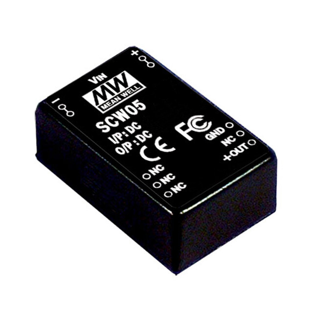
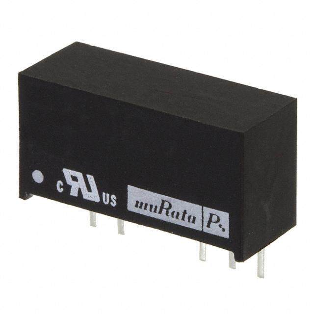
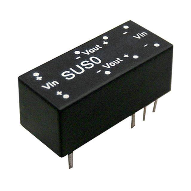
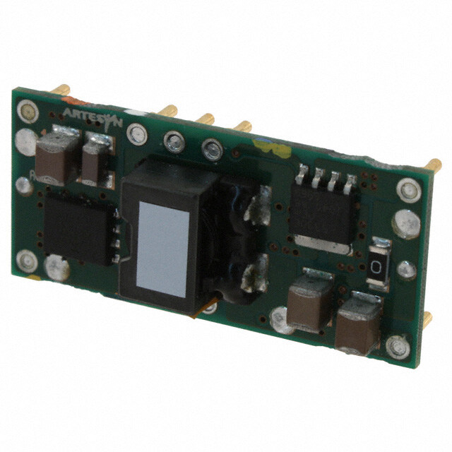
- 型号: PTH12010YAZ
- 制造商: Texas Instruments
- 库位|库存: xxxx|xxxx
- 要求:
| 数量阶梯 | 香港交货 | 国内含税 |
| +xxxx | $xxxx | ¥xxxx |
查看当月历史价格
查看今年历史价格
PTH12010YAZ产品简介:
ICGOO电子元器件商城为您提供PTH12010YAZ由Texas Instruments设计生产,在icgoo商城现货销售,并且可以通过原厂、代理商等渠道进行代购。 PTH12010YAZ价格参考¥148.84-¥230.50。Texas InstrumentsPTH12010YAZ封装/规格:直流转换器, 非隔离 PoL 模块 DC/DC 转换器 1 输出 0.55 ~ 1.8 V 15A 10.8V - 13.2V 输入。您可以下载PTH12010YAZ参考资料、Datasheet数据手册功能说明书,资料中有PTH12010YAZ 详细功能的应用电路图电压和使用方法及教程。
| 参数 | 数值 |
| 产品目录 | |
| 描述 | MODULE PIP .55-1.8V 12A SMD10DIP非隔离式DC/DC转换器 15A 12V-In Bus Term Pwr Mdl for DDR/QDR |
| 产品分类 | DC DC ConvertersDC/DC转换器 |
| 品牌 | Texas Instruments |
| 产品手册 | |
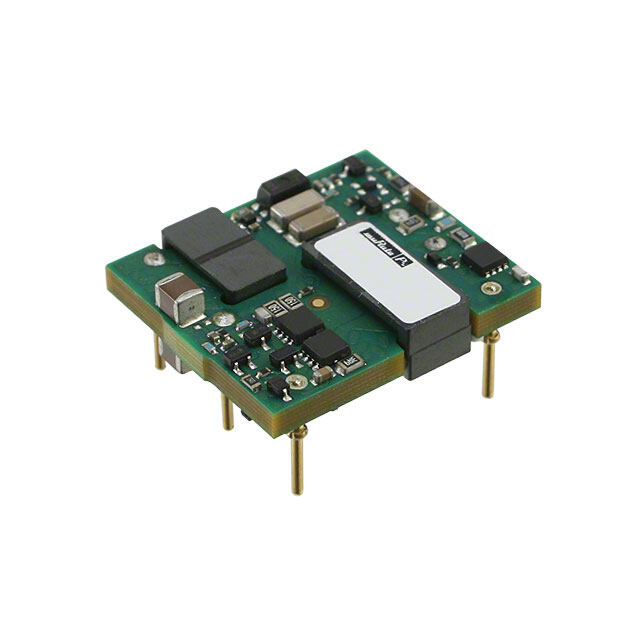
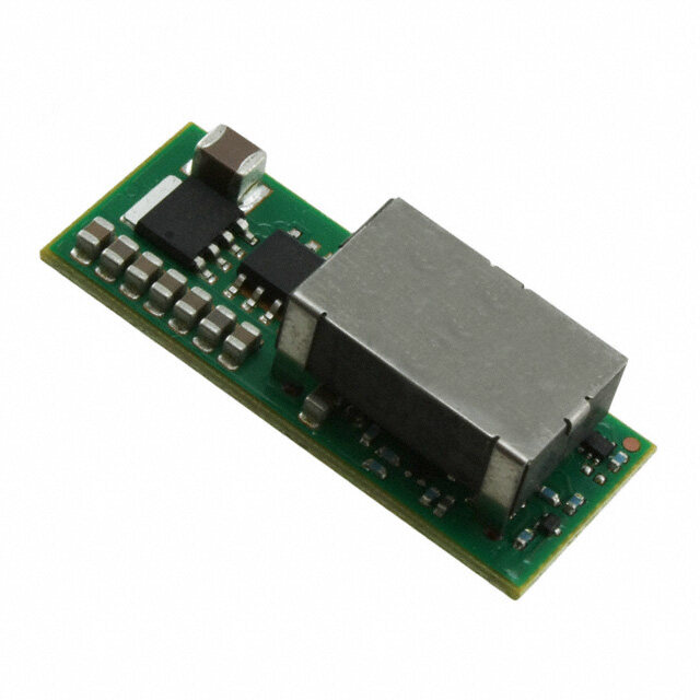
| 产品图片 |
|
| rohs | 符合RoHS无铅 / 符合限制有害物质指令(RoHS)规范要求 |
| 产品系列 | 非隔离式DC/DC转换器,Texas Instruments PTH12010YAZPTH12010 |
| 数据手册 | |
| 产品型号 | PTH12010YAZ |
| 产品 | Non-Isolated / POL |
| 产品目录页面 | |
| 产品种类 | 非隔离式DC/DC转换器 |
| 其它名称 | 296-20459 |
| 制造商产品页 | http://www.ti.com/general/docs/suppproductinfo.tsp?distId=10&orderablePartNumber=PTH12010YAZ |
| 功率(W)-制造系列 | 22W |
| 功率(W)-最大值 | 22W |
| 包装 | 托盘 |
| 商标 | Texas Instruments |
| 大小/尺寸 | 1.37" 长 x 0.62" 宽 x 0.38" 高(34.8mm x 15.7mm x 9.7mm) |
| 安装类型 | 表面贴装 |
| 安装风格 | SMD/SMT |
| 封装 | Tray |
| 封装/外壳 | 10-SMD 模块 |
| 封装/箱体尺寸 | Surface Mount Module |
| 工作温度 | -40°C ~ 85°C |
| 工作温度范围 | - 40 C to + 85 C |
| 工厂包装数量 | 25 |
| 效率 | 85% |
| 标准包装 | 25 |
| 特性 | 远程开/关,OCP,UVLO |
| 电压-输入(最大值) | 13.2V |
| 电压-输入(最小值) | 10.8V |
| 电压-输出1 | 0.55 ~ 1.8 V |
| 电压-输出2 | - |
| 电压-输出3 | - |
| 电压-隔离 | - |
| 电流-输出(最大值) | 12A |
| 类型 | 非隔离 PoL 模块 |
| 系列 | PTH12010Y |
| 输入电压范围 | 10.8 V to 13.2 V |
| 输出数 | 1 |
| 输出电流—通道1 | 12 A |




- 商务部:美国ITC正式对集成电路等产品启动337调查
- 曝三星4nm工艺存在良率问题 高通将骁龙8 Gen1或转产台积电
- 太阳诱电将投资9.5亿元在常州建新厂生产MLCC 预计2023年完工
- 英特尔发布欧洲新工厂建设计划 深化IDM 2.0 战略
- 台积电先进制程称霸业界 有大客户加持明年业绩稳了
- 达到5530亿美元!SIA预计今年全球半导体销售额将创下新高
- 英特尔拟将自动驾驶子公司Mobileye上市 估值或超500亿美元
- 三星加码芯片和SET,合并消费电子和移动部门,撤换高东真等 CEO
- 三星电子宣布重大人事变动 还合并消费电子和移动部门
- 海关总署:前11个月进口集成电路产品价值2.52万亿元 增长14.8%

PDF Datasheet 数据手册内容提取
process yellow 116 1375 1797 375 3405 313 2985 240 Embedded Power for Business-Critical Continuity 242 2607 Rev. 3.23.09_73 PTHxx010Y Series 652 PTHxx010Y 1 of 5 3.3/5/12 Vin Total Power: 27 Watts # of Outputs: Single Specifications Input Special Features Input current: No load 10 mA • VTT bus termination output Input voltage range: PTH03010Y 2.95 - 3.65 Vdc (output the system VREF) PTH05010Y 4.5 - 5.5 Vdc • 15 A output current PTH12010Y 10.8 - 13.2 Vdc • 3.3, 5, or 12 Vdc input voltage Undervoltage lockout: • DDR and QDR compatible • ON/OFF inhibit ( for VTT stand- PTH03010Y Vin increasing 2.45 V typ., 2.80 V max. by) Vin decreasing 2.20 V min., 2.40 V typ. • Under-voltage lockout • Operating temperature range: PTH05010Y Vin increasing 4.30 V typ., 4.45 V max. -40 °C to +85 °C Vin decreasing 3.40 V min., 3.70 V typ. • Efficiencies up to 91% PTH12010Y Vin increasing 9.5 V typ., 10.4 V max. • Output overcurrent protection Vin decreasing 8.80 V min., 9.0 V typ. (non-latching, auto-reset) • Point-of-Load-Alliance (POLA) Input capacitance: PTH03010Y & PTH05010Y 470 µF compatible (See Note 3, page 3) PTH12010Y 560 µF • Available RoHS compliant • 2 Year Warranty Remote ON/OFF: Positive logic All specifications are typical at nominal input, VREF = 1.25 V, full load at 25 °C unless otherwise stated Cin, Co1, C Co2 = typical value Safety • UL/cUL CAN/CSA-C22.2 No. 60950 File No. E174104 • TÜV Product Service (EN60950) Certificate No. B 04 06 38572 044 • CB Report and Certificate to IEC60950, Certificate No. US/8292/UL
process yellow 116 1375 1797 375 3405 313 2985 240 242 Embedded Power for Business-Critical Continuity 2607 Rev. 3.23.09_73 Specifications Continued PTHxx010Y Series 652 2 of 5 Output Output current: PTH03010Y & PTH05010Y ± 15 A (over VVREF range) PTH12010Y ± 12 A (See Note 1, page 3) Tracking range for VREF: 0.55 - 1.8 V Tracking tolerance to VREF (VTT - VREF): -10 mV to + 10 mV (over line, load & temperature) Ripple and noise: 20 MHz bandwidth 20 mV pk-pk Load transient response: 30 µµss sseettttlliinngg ttiimmee (See Note 4, page 3) Overshoot/undershoot 30 mV typ. Output capacitance: Non-ceramic values PTH03010Y 470 µµFF ttyypp..,, 88,,220000 µµFF mmaaxx.. (See Notes 4 & 5, page 3) PTH05010Y 470 µµFF ttyypp..,, 88,,220000 µµFF mmaaxx.. PTH12010Y 940 µµFF ttyypp..,, 66,,660000 µµFF mmaaxx.. Ceramic values PTH03010Y 200 µµFF ttyypp..,, 330000 µµFF mmaaxx.. (See Note 4, page 3) PTH05010Y 200 µµFF ttyypp..,, 330000 µµFF mmaaxx.. PTH12010Y 400 µµFF ttyypp..,, 660000 µµFF mmaaxx.. (See Note 6, page 3) ESR (non-ceramic) 4 mΩ min. General Specifications Efficiency: PTH03010Y 88% typ. lo = 10 A PTH05010Y 88% typ. PTH12010Y 85% typ. Insulation voltage: Non-isolated Switching frequency: PTH03010Y 300 - 400 kHz PTH05010Y 300 - 400 kHz PTH12010Y 200 - 300 kHz Approvals and standards: EN60950 UL/cUL60950 Material flammability: UL94V-0 Dimensions: (L x W x H) 34.80 x 15.75 x 9.00 mm 1.370 x 0.620 x 0.354 in Weight: 3.7 g (0.13 oz) MTBF: Telcordia SR-332 6,000,000 hours Environmental Specifications Thermal Performance: Operating ambient, temperature -40 °C to +85 °C (See Note 2, page 3) Non-operating -40 °C to +125 °C MSL (‘Z’ suffix only): JEDEC J-STD-020C Level 3 Protection Overcurrent threshold (auto reset): PTH03010Y & PTH05010Y 27.5 A typ. PTH12010Y 20.0 A typ.
process yellow 116 1375 1797 375 3405 313 2985 240 242 Embedded Power for Business-Critical Continuity 2607 Rev. 3.23.09_73 PTHxx010Y Series 3 of 5 652 Ordering Information Output Power Input VTT Output Currents Efficiency Mooddeell NNuummbbeerrss (8, 9) (max) Voltage Range Min Max (max) 27 W 2.95 - 3.65 Vdc 0.55 - 1.8 Vdc 0 A ± 15 A 88% PTH03010Y 27 W 4.5 - 5.5 Vdc 0.55 - 1.8 Vdc 0 A ± 15 A 88% PTH05010Y 21.6 W 10.8 - 13.2 Vdc 0.55 - 1.8 Vdc 0 A ± 15 A 85% PTH12010Y Part Number System with Options P T H 0 5 0 1 0 Y A S T Product Family Packaging Options Point of Load Alliance No Suffix = Trays Compatible T = Tape and Reel (7) Input Voltage Mounting Option (8) 03 = 3.3 V, 05 = 5 V D = Horizontal Through-Hole (RoHS 6/6) and 12 = 12 V H = Horizontal Through-Hole (RoHS 5/6) S = Surface-Mount Solder Ball (RoHS 5/6) Output Current Z = Surface-Mount Solder Ball (RoHS 6/6) 01 = 15 A Pin Option Mechanical Package A = Through-Hole Std. Pin Length (0.140”) Always 0 A = Surface-Mount Tin/Lead Solder Ball Output Voltage Code Y = DDR Module Notes 1 Rating is conditional on the module being soldered to a 4 layer PCB 5 This is the calculated maximum. The minimum ESR limitation will with 1 oz. copper. See the SOA curves or contact the factory for often result in a lower value. Consult Application Note 177 for appropriate derating. further details. 2 This control pin has an internal pull-up to the input voltage Vin. If 6 This is the typical ESR for all the electrolytic (non-ceramic) output it is left open-circuit the module will operate when input power is capacitance. Use 7 mΩ as the minimum when using max-ESR applied. A small low-leakage (< 100 nA) MOSFET is recommended values to calculate. for control. For further information, consult Application Note 177. 7 Tape and reel packaging only available on the surface-mount 3 An input capacitor is required for proper operation. The capacitor versions. must be rated for a minimum of 800 mA rms of ripple current. 8 To order Pb-free (RoHS compatible) surface-mount parts replace 4 The typical value of external output capacitance value ensures that the mounting option ‘S’ with ‘Z’, e.g. PTHXX010YAZ. To order Pb- VTT meets the specified transient performance requirements for free (RoHS compatible) through-hole parts replace the mounting the memory bus terminations. Lower values of capacitance may option ‘H’ with ‘D’, e.g. PTHXX010YAD. be possible when the measured peak change in output current is 9 NOTICE: Some models do not support all options. Please contact consistently less than 3 A. Test conditions were 15 A/µs load step, your local Emerson Network Power representative or use the on-line -1.5 A to +1.5 A. model number search tool at http://www.PowerConversion.com to find a suitable alternative.
process yellow 116 1375 1797 375 3405 313 2985 240 242 Embedded Power for Business-Critical Continuity 2607 Rev. 3.23.09_73 PTHxx010Y Series 652 Characteristic Data 4 of 5 16 14 T (A) 14 T (A) 12 EN 12 EN 10 CURR 108 N10a0t cLoFnMv CURR 8 N10a0t cLoFnMv T 200 LFM T 6 200 LFM U 6 U P P T T 4 U 4 U O O 2 2 0 0 0 10 20 30 40 50 60 70 80 0 10 20 30 40 50 60 70 80 AMBIENT TEMPERATURE (ºC) AMBIENT TEMPERATURE (ºC) Figure 1 - Safe Operating Area Figure 2 - Safe Operating Area Vin = 3.3 V, VREF = 1.25 V, Iout = 15 A (See Note A) Vin = 12 V, VREF = 1.25 V, Iout = 12 A (See Note A) Vin 100 VDDQ VREF 90 11 k% 1 109 8 7 VTT ENCY (%) 80 Vin351..230.VV0V 11 %k 2 3P(TTo4Hpx Vx0i5e1w0)Y 6 hCfo-nCeramic FFICI 70 C(Rine quired) + CLoow1-ESR +Co2 TT VTerm SDSaTtaL-/2 E 60 StGanNdDby QB(OS1Sp1ti3o8nal) (Required) C(Oepratmionical) ination Island ABudsdress/ 50 0 3 6 9 12 15 OUTPUT CURRENT (A) Figure 3 - Efficiency vs Load Current Figure 4 - Standard Application VREF = 1.25 V (See Note B) Notes A SOA curves represent the conditions at which internal components are within the Emerson Network Power derating guidelines. B Characteristic data has been developed from actual products tested at 25 °C. This data is considered typical data for the converter.
process yellow 116 1375 1797 375 3405 313 2985 240 Embedded Power for Business-Critical Continuity 242 2607 Mechanical Drawings Rev. 3.23.09_73 PTHxx010Y Series 652 5 of 5 Americas 1.370 (34.80) 5810 Van Allen Way 0.140 0.125 (3.18) (3.55) Carlsbad, CA 92008 0.125 (3.18) 0.060 USA 0.060 0.375 0.625 (15.88) (1.52) Telephone: +1 760 930 4600 (1.52) (9.52) ø0.040 (1.02) 5 Places Facsimile: +1 760 930 0698 1 10 9 8 7 Europe (UK) 0.070 (1.78) Waterfront Business Park 0.500 0.620 (Standoff Shoulder) Merry Hill, Dudley (15.75) (12.70) West Midlands, DY5 1LX United Kingdom Lowest Component 0.010 min. (0.25) Telephone: +44 (0) 1384 842 211 2 3 4 5 6 Bottom side Clearance Facsimile: +44 (0) 1384 843 355 Asia (HK) TOP VIEW 14/F, Lu Plaza Host Board 2 Wing Yip Street Kwun Tong, Kowloon 0.354 (9.00) Hong Kong Dimensions in Inches (mm) MAX. Telephone: +852 2176 3333 Tolerances (unless otherwise specified) 2 Places 0.030 (0.76) SIDE VIEW Facsimile: +852 2176 3888 3 Places 0.010 (0.25) For global contact, visit: Figure 5 - Plated Through-Hole www.PowerConversion.com techsupport.embeddedpower @emerson.com 1.370 (34.80) While every precaution has been taken to ensure 0.125 (3.18) accuracy and completeness in this literature, Emerson 0.060 0.125 0(3.3.1785) 0.625 (15.88) 0(1.0.5620) 0.3m54a x(9.*.00) *oAn fctuesr tsoomldeerr breofalordw Nainlelf oltiwarmboiraliktt iyPo ofnow or erd rfa oamrs saaugnmey see rsrer nosours lrt oeinsr gpo omfrnoissmisbi ioulintsyse., oafn tdh idsi s claims (1.52) (9.52) Emerson Network Power. 1 10 9 8 7 Solder Ball The global leader in enabling ø0.040 (1.02) business-critical continuity. 10 Places 0.620 0.500 (15.75) (12.70) AC Power Lowest Component 0.010 min. (0.25) Connectivity Bottom side Clearance 2 3 4 5 6 DC Power Embedded Computing TOP VIEW SIDE VIEW Host Board Embedded Power Dimensions in Inches (mm) Monitoring Tolerances (unless otherwise specified) 2 Places 0.030 (0.76) Outside Plant 3 Places 0.010 (0.25) Power Switching & Controls Figure 6 - Surface-Mount Precision Cooling Pin Connections Pin Connections cont. Racks & Integrated Cabinets Services Pin No. Function Pin No. Function Surge Protection Pin 1 Ground Pin 6 VTT Pin 2 Vin Pin 7 Ground EmersonNetworkPower.com Pin 3 Inhibit* Pin 8 VREF Emerson Network Power and the Emerson Network Power logo are trademarks and Pin 4 N/C Pin 9 N/C * Denotes negative logic: service marks of Emerson Electric Co. Open = Normal operation ©2008 Emerson Electric Co. Pin 5 Vo sense Pin 10 N/C Ground = Function active
 Datasheet下载


