ICGOO在线商城 > 音频产品 > 警报器,蜂鸣器,警笛 > PT-2040PQ
 Datasheet下载
- 型号: PT-2040PQ
- 制造商: MALLORY
- 库位|库存: xxxx|xxxx
- 要求:
| 数量阶梯 | 香港交货 | 国内含税 |
| +xxxx | $xxxx | ¥xxxx |
查看当月历史价格
查看今年历史价格
PT-2040PQ产品简介:
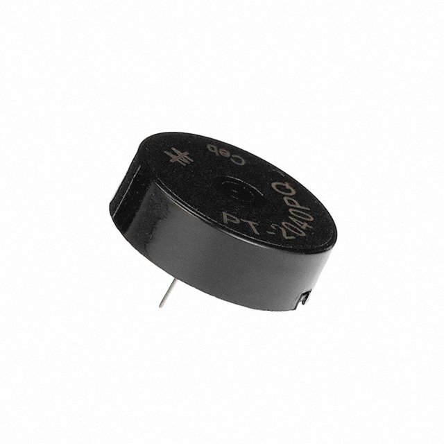
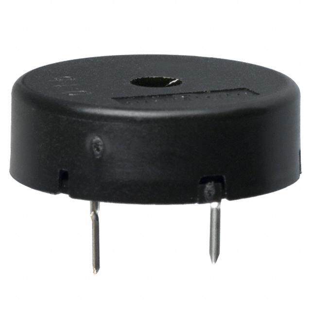
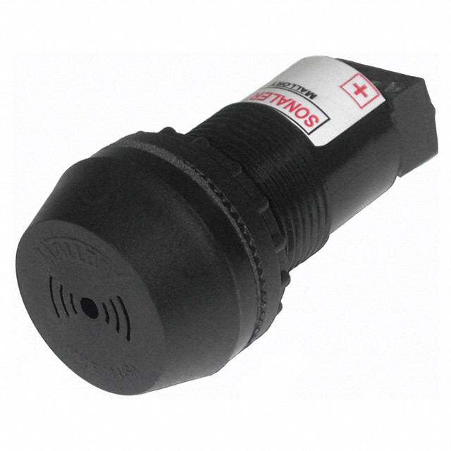
ICGOO电子元器件商城为您提供PT-2040PQ由MALLORY设计生产,在icgoo商城现货销售,并且可以通过原厂、代理商等渠道进行代购。 PT-2040PQ价格参考。MALLORYPT-2040PQ封装/规格:警报器,蜂鸣器,警笛, 压电 蜂鸣器 传感器,外部驱动 5V 1.5mA 4kHz 90dB @ 5V,10cm 通孔 PC 引脚。您可以下载PT-2040PQ参考资料、Datasheet数据手册功能说明书,资料中有PT-2040PQ 详细功能的应用电路图电压和使用方法及教程。
| 参数 | 数值 |
| 产品目录 | |
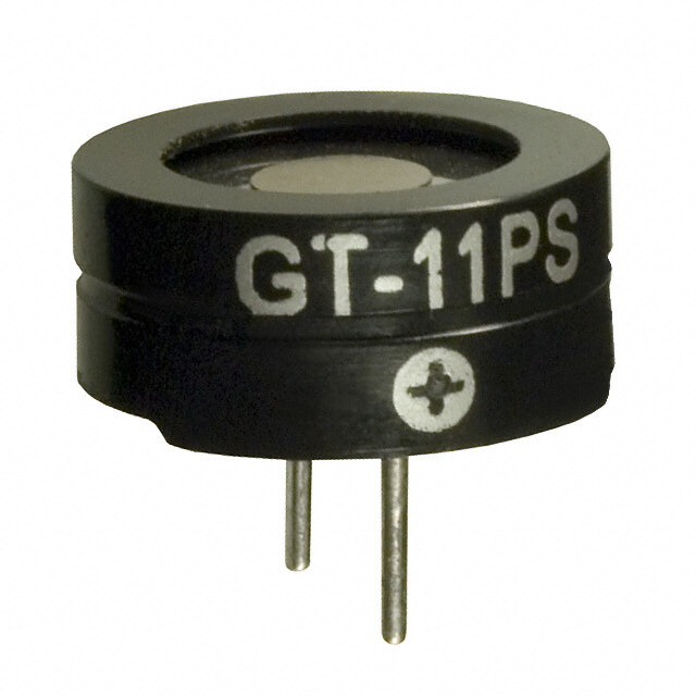
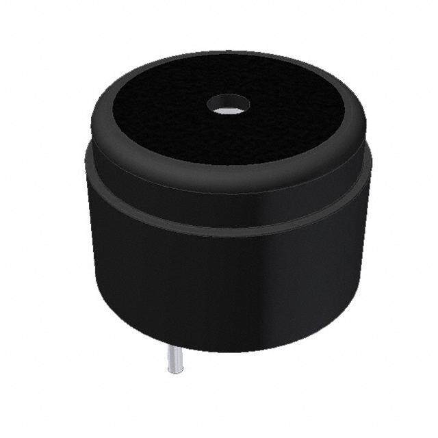
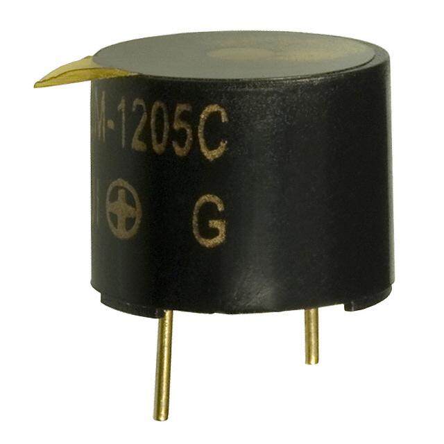
| 描述 | BUZZER PIEZO 4KHZ 22MM PC MT音频指示器及警报器 XDUCR, PIEZO, 4KHZ 90DB, PC PINS, 22X9 |
| 产品分类 | 蜂鸣器音频设备 |
| 品牌 | Mallory Sonalert |
| 产品手册 | |
| 产品图片 |
|
| rohs | 符合RoHS无铅 / 符合限制有害物质指令(RoHS)规范要求 |
| 产品系列 | 音频指示器及警报器,Mallory Sonalert PT-2040PQSonalert® |
| mouser_ship_limit | 该产品可能需要其他文件才能进口到中国。 |
| 数据手册 | |
| 产品型号 | PT-2040PQ |
| 不同频率时的电容 | 25000pF @ 120Hz |
| 产品 | Transducers |
| 产品目录绘图 |
|
| 产品目录页面 | |
| 产品种类 | 音频指示器及警报器 |
| 其它名称 | 458-1078 |
| 包装 | 散装 |
| 可水洗 | 无 |
| 商标 | Mallory Sonalert |
| 声压级 | 90 dB |
| 大小/尺寸 | 圆形 - 22.00mm 直径 x 7.20mm 高 |
| 安装类型 | 通孔 |
| 尺寸 | 9 mm H |
| 工作模式 | 连续 |
| 工作温度 | -20°C ~ 90°C |
| 工作温度范围 | - 20 C to + 90 C |
| 工作电压 | 30 V |
| 形状 | Round |
| 技术 | 压电 |
| 标准包装 | 1 |
| 深度 | 7 mm |
| 电压-额定 | 5Vp-p |
| 电压范围 | 30V(最小值) |
| 电流-电源 | 1.5mA |
| 直径 | 22 mm |
| 端接 | PC 引脚 |
| 端接类型 | Solder Pin |
| 类型 | Piezoelectric |
| 系列 | PT |
| 输入类型 | 峰值-峰值信号 |
| 频率 | 4000 Hz |
| 驱动器电路 | 传感器,外部驱动 |
| 高度 | 9 mm |


- 商务部:美国ITC正式对集成电路等产品启动337调查
- 曝三星4nm工艺存在良率问题 高通将骁龙8 Gen1或转产台积电
- 太阳诱电将投资9.5亿元在常州建新厂生产MLCC 预计2023年完工
- 英特尔发布欧洲新工厂建设计划 深化IDM 2.0 战略
- 台积电先进制程称霸业界 有大客户加持明年业绩稳了
- 达到5530亿美元!SIA预计今年全球半导体销售额将创下新高
- 英特尔拟将自动驾驶子公司Mobileye上市 估值或超500亿美元
- 三星加码芯片和SET,合并消费电子和移动部门,撤换高东真等 CEO
- 三星电子宣布重大人事变动 还合并消费电子和移动部门
- 海关总署:前11个月进口集成电路产品价值2.52万亿元 增长14.8%

.jpg)
PDF Datasheet 数据手册内容提取
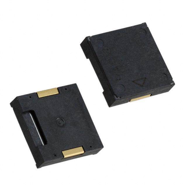
Product Application Guide- Transducers- External Drive- Piezo Part Numbering System Transducer Series (PT / AST) Part Number Structure PT – 1224 P E-05 Q Series PT = Piezoelectric Transducer Unique Identifier Drive Type & Termination FP = Feedback Design & PC Pins P = External Drive & PC Pins FW = Feedback Design & Wires W = External Drive & Wires Special Designator RoHS: Q = RoHS Compliant Part Number Structure AST 605 TR Q Series: AST = Surface Mount Unique Identifier Termination: TR = Tape-N-Reel RoHS: Q = RoHS Compliant
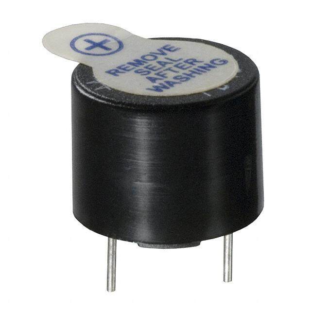
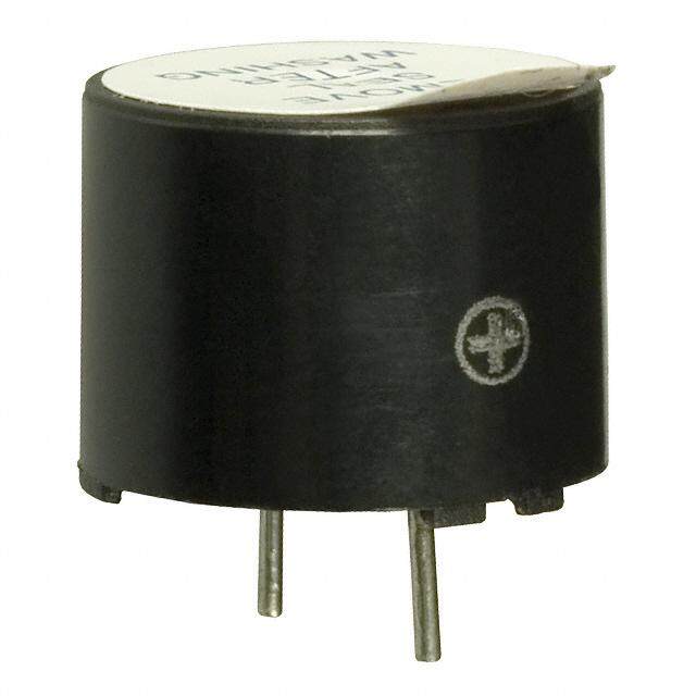
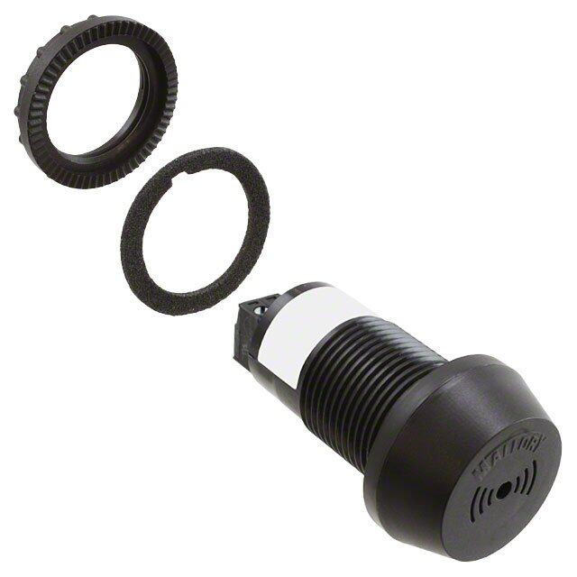
Page 2 Piezoelectric Electronic Alarm Construction The above cross section picture shows the basic elements used in a piezoelectric audible alarm. The area in front of the transducer element including the front hole opening forms an acoustic cavity that lets the sound radiate out with the most efficiency (i.e. loudest sound level). If the alarm is an indicator that contains a circuit board, the circuit board is attached to the piezoelectric sounder element via soldered wires. The above picture can be interpreted to represent a board mount package with pc pin terminations, but the same concept is used when building audible alarms in other mounting configurations such as SMT, Flange Mount, and Panel Mount alarms. If the back of the alarm is sealed with epoxy or other material, the “guts” of the alarm (including the circuit board and components) are protected against fluid intrusion. However, fluid sitting inside the front cavity can obstruct the operation of the device causing the sound level to decrease significantly. If you need to wash the alarms after a soldering operation, it is strongly recommended to use an alarm that comes with a wash label that keeps the washing fluid from getting inside of the front cavity.
Page 3 Operation of Piezoelectric Audible Alarms Piezoelectric electronic audible alarms work by converting the user input voltage to an appropriate oscillating signal that is applied to a sounder element that is mounted in a housing. The piezoelectric sounder element consists of a metal disc that has a special ceramic material bonded to it that physically bends when voltage is applied to it. The above picture shows a bare piezoelectric sounder element. By applying a sinusoidal wave- form at an appropriate frequency, the transducer will physically deflect in one direction and then in the opposite direction following the shape of the input wave-form. If this oscillation occurs in the audible frequency range (1 Hz to 20 kHz), then air pressure waves are produced that the human ear interprets as an audible sound. The larger the voltage of the applied wave-form, the larger the amplitude of the air pressure waves resulting in a louder sound level. However, the ceramic portion of the transducer can only bend so far before there is a risk of a catastrophic failure. This maximum voltage is somewhere around 40 to 50 volts. However, it is rare to apply this much voltage to a transducer as you reach a point of diminishing returns for voltages much greater than 32 volts. By itself, the sound level produced by a transducer element is insignificant. To increase the size of the air pressure waves (and thus the sound level), the transducer element must be mounted inside an acoustic chamber that is optimized for the transducer size and resonant frequency. Every transducer has one frequency where it flexes more efficiently producing the louder sound levels. This frequency where the transducer performs the best is called the resonant frequency. Self-Drive type devices provide a 3rd terminal that connects to an isolated portion of the piezoelectric transducer. This third terminal provides a feed-back signal that is 180 degrees out of phase with the drive signal. This signal can be fed back into the circuit to allow the sounder element to self-tune itself to the transducer’s resonant frequency.
Page 4 Decibel Sound Level Scale The decibel sound level scale is an arbitrary scale that ranges from 0 dB (threshold of hearing) to 130 dB (threshold of pain). The chart below shows where some common sounds fall on this dB scale. Audible alarms are available that have sound levels as soft as 55 dB at 2 feet and as loud as 110 dB at 2 feet.
Page 5 Fundamental Frequency & Harmonics Below is a frequency scan of a piezoelectric audible alarm that has a resonant frequency of 2,800 Hz. As you can see, there is a strong frequency peak at 2.8 kHz and several smaller frequency peaks that follow called harmonic frequencies. The table below the chart shows that the size of the harmonic frequencies are significantly smaller than the fundamental frequency for this particular alarm unit. Because this alarm has a large fundamental frequency and much smaller harmonic frequencies, the sound quality of this part will be very good. When this alarm is activated, the listener will hear one clear frequency (also called sound pitch) from the alarm. Other electronic alarm technologies such as electro-magnetic or electro-mechanical type alarms often have much larger harmonic frequency components resulting in less clear tone.
Page 6 Circuit to Increase Turn-On Voltage Below is a circuit that can be used to prevent the alarm from sounding until a certain voltage is reached. This particular circuit has a turn-on voltage around 10 Vdc due to the 10 volt Zener Diode, but you can just substitute other values of Zener Diodes to get the needed turn-on voltage for your circuit.
Page 7 Controlling Sound Level- Electronic Method For piezoelectric type audible alarms, the larger the voltage signal applied to the piezoelectric transducer, the louder the sound level. This property can be used to electronically control the sound level of these devices. For audible alarm model MSR320R, the sound level will vary from 65 dB at 2 ft. at 3 Vdc up to 80 dB at 2 ft. at 20 Vdc. By varying the voltage from 3 to 20 Vdc, the sound level can be varied by 15 dB. A 10 dB drop in sound level will make the alarm sound half as loud. There are several ways of electronically controlling the voltage including: 1. Using a manual or digital potentiometer. 2. Using a selector circuit and different values of resistors. 3. Using PWM voltage signals from microcontrollers. In all cases, care must be taken to make sure that the circuitry and voltage signals used do not interfere with the internal circuitry of the audible alarm. This method of controlling the sound level will probably not work well in the following cases: 1. The sound level of electro-magnetic type alarms do not vary much over the voltage range of these devices, so most electro-magnetic type alarms are not suitable for this method. 2. When you only have a narrow operating voltage range to work with. For example, if you are using the MSR320R at 5 Vdc, the sound level change from 5 Vdc to 3 Vdc is not very much. 3. When the voltage range of the audible alarm is narrow. For example, panel mount model SC307NR only has a voltage range of 3 to 7 Vdc. Over this range, the sound level will vary by only 6 dB. This sound level change is significant, but may not be enough to make a difference in the application.
Page 8 External Drive Transducer Circuits External Drive Transducers require a sine or square wave type signal at the appropriate frequency for the transducer. A sine-wave type signal will produce more sound level than a square-wave type signal. The higher the voltage level (up to the maximum allowed) the higher the sound level will be. Below are two circuits that can be used with external drive transducer devices: It should be noted that the component values given are starting points only. For example, the inductor shown is optional and the value of the inductor will definitely have to be adjusted depending on the transducer used. Also, the oscillator portion of the transistor circuit will have to be adjusted to match the resonant frequency of the transducer.
Page 9 Tube and Tape-n-Reel Counts- All P/N’s Tube Reel Tube Reel Part Number Count Count Part Number Count Count ASI301Q 35 AST612Q 35 ASI301TRQ 250 AST612TRQ 450 ASI401Q 35 AST7525MATRQ 1000 ASI401TRQ 250 PB-1220PQ 40 AST100Q 25 PB-1221PQ 40 AST100TRQ 500 PB-1224PE-05Q 40 AST1109MLTRQ 1000 PB-12N23P-01Q 40 AST1240MLTRQ 1000 PB-12N23P-03Q 40 AST1440MATRQ 600 PB-12N23P-05Q 40 AST1575BMATRQ 300 PB-12N23P-12Q 40 AST1628MATRQ 800 AST1750MATRQ 400 AST200Q 48 AST200TRQ 1000 AST501Q 35 AST501TRQ 450 AST605Q 35 AST605TRQ 300
Page 10 Typical Failure Modes of Piezoelectric Audible Alarms Component/Subsystem Failure Mode End Result Occurrence Circuit Components Over-voltage by customer’s Unit ceases working. Vast (Resistors, Capacitors, application Majority of Diodes, IC’s, etc.) Returns Transducer/Wire Solder Not enough wire strands in Wire breaks after Rare Operation solder joint period of time & unit ceases sounding Physical Assembly Transducer wire pinched, Intermittent operation Rare adhesive/epoxy run down onto transducer, or RTV adhesive seal failure Soldering Operation Incorrect Solder Temperature Intermittent operation Very Rare or Time Causing Cold Solder or unit ceases working Joint after period of time Circuit Components Random Component Failure; Unit ceases working Very Rare Wrong Component Used; under normal Missing Component operating conditions Transducer Wire Defect in Wire; Wire breaks after Very Rare Wire Strands Damaged in period of time & unit Production ceases sounding Piezo Transducer Incorrect Polarization by Sound volume level Exceedingly Manufacturer; decreases over time. Rare Glue Bonding Failure Notes: 1. Customer returns of Mallory audible alarms for failure to operate are very rare. Of the few parts returned each year, the vast majority of the root cause of failure is an over- voltage or voltage spike condition caused by the customer’s application. 2. All Mallory alarms are, at a minimum, function tested 100% during production, and a final audit is performed. Mallory SC/SBM/SBT/SBS/SNP/LSC/VSB/MSR/MSO/ZA series of alarms are audited 100% at final test by checking that sound level, frequency, and current are within specification limits from 2 to 4 different voltage levels.