ICGOO在线商城 > 电路保护 > PTC 可复位保险丝 > PRG21BC1R0MM1RA

 Datasheet下载
- 型号: PRG21BC1R0MM1RA
- 制造商: Murata
- 库位|库存: xxxx|xxxx
- 要求:
| 数量阶梯 | 香港交货 | 国内含税 |
| +xxxx | $xxxx | ¥xxxx |
查看当月历史价格
查看今年历史价格
PRG21BC1R0MM1RA产品简介:
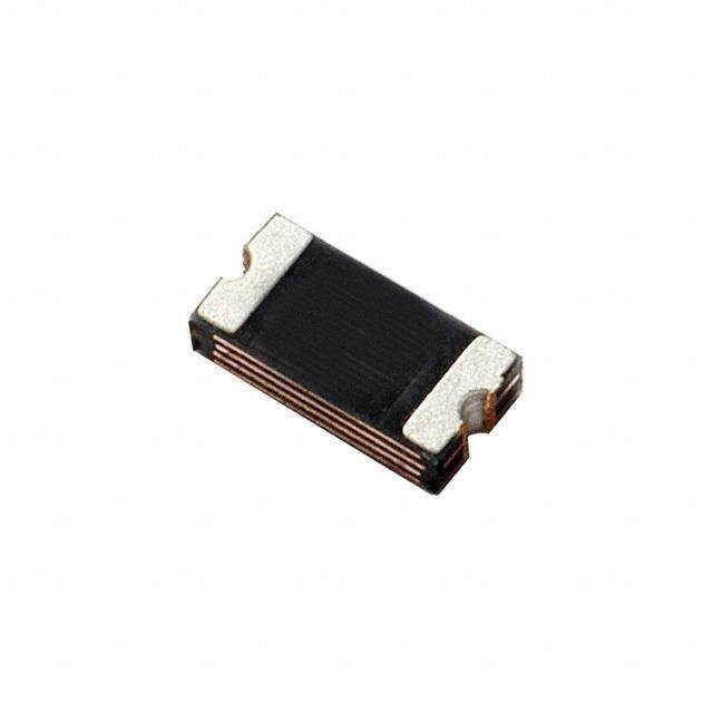
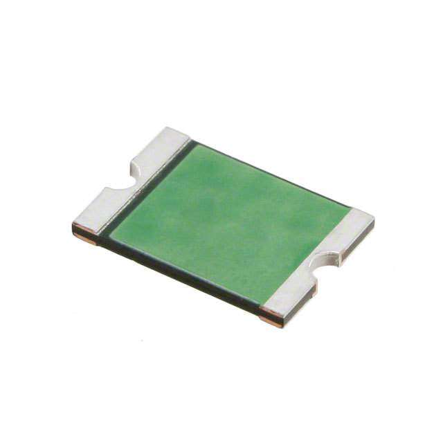
ICGOO电子元器件商城为您提供PRG21BC1R0MM1RA由Murata设计生产,在icgoo商城现货销售,并且可以通过原厂、代理商等渠道进行代购。 PRG21BC1R0MM1RA价格参考。MurataPRG21BC1R0MM1RA封装/规格:PTC 可复位保险丝, 陶瓷 PTC 自恢复保险丝 12V 330mA Ih 表面贴装 0805(2012 公制)。您可以下载PRG21BC1R0MM1RA参考资料、Datasheet数据手册功能说明书,资料中有PRG21BC1R0MM1RA 详细功能的应用电路图电压和使用方法及教程。
| 参数 | 数值 |
| 产品目录 | |
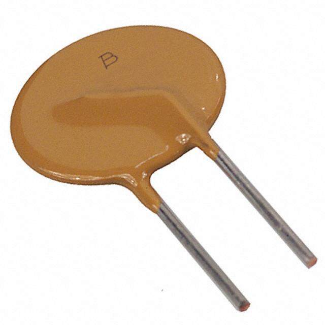
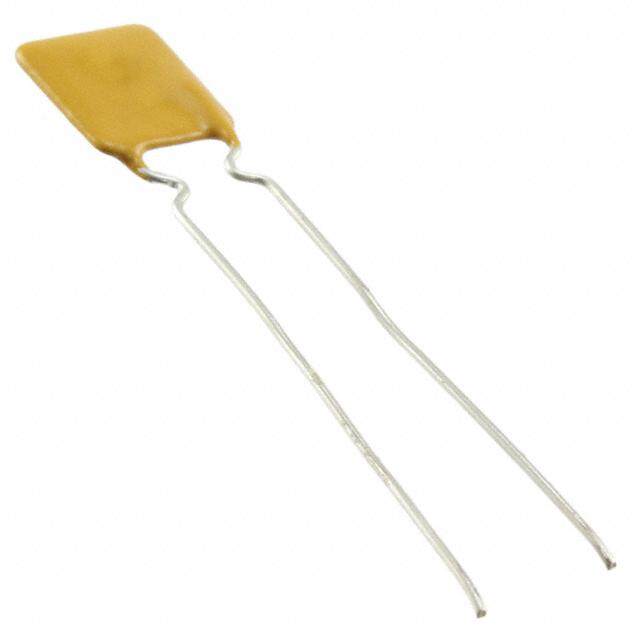
| 描述 | THERMISTOR热敏电阻 - PTC 1.0 Ohm 20% 12volts |
| 产品分类 | |
| 品牌 | Murata Electronics |
| 产品手册 | http://search.murata.co.jp/Ceramy/CatalogAction.do?sHinnm=? &sNHinnm=PRG21BC1R0MM1RA&sNhin_key=PRG21BC1R0MM1RA&sLang=en&sParam=PRG21 |
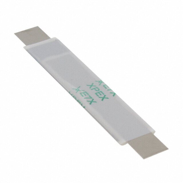
| 产品图片 |
|
| rohs | 符合RoHS无铅 / 符合限制有害物质指令(RoHS)规范要求 |
| 产品系列 | Murata Electronics PRG21BC1R0MM1RAPOSISTOR® PRG18BC |
| 数据手册 | |
| 产品型号 | PRG21BC1R0MM1RA |
| R(最小/最大值) | - |
| 产品培训模块 | http://www.digikey.cn/PTM/IndividualPTM.page?site=cn&lang=zhs&ptm=5799 |
| 产品目录绘图 |
|
| 产品种类 | 热敏电阻 - PTC |
| 其它名称 | 490-8511-1 |
| 包装 | 剪切带 (CT) |
| 商标 | Murata Electronics |
| 容差 | 20 % |
| 封装 | Ammo Pack |
| 封装/外壳 | 0805(2012 公制) |
| 尺寸 | 1.25 mm W x 2 mm L x 0.9 mm H |
| 工作温度范围 | - 10 C to + 60 C |
| 工厂包装数量 | 4000 |
| 标准包装 | 1 |
| 电压 | 12 V |
| 电压-最大值 | 12V |
| 电流-保持(Ih)(最大值) | 330mA |
| 电流-最大值 | 10A |
| 电流-跳闸(It) | 740mA |
| 电流额定值 | 10 A |
| 电阻 | 1 Ohms |
| 端接类型 | SMD/SMT |
| 类型 | PTC |
| 跳闸时间 | - |

.jpg)


PDF Datasheet 数据手册内容提取
® Posistor for over current protection PRG SERIES BC-E0273H PRG21BC***MM1RA SERIES 1.Part Numbering ex) PR G 21 BC 0R2 M M1 RA C Product ID Series Dimensions Temperature Resistance Resistance Individual Packaging Characteristics Tolerance Specifications 2. Ratings (*4) *1 *2 *3 Part Number Resistance Max. Max. Hold Current Trip Current (at 25°C) Voltage Current 750mA (at +25°C) 2100mA (at -20°C) 0.2ohm PRG21BC0R2MM1RA DC6V 10.0A 500mA (at +60°C) 2000mA (at -10°C) ±20% 315mA (at +85°C) 1620mA (at +25°C) 420mA (at +25°C) 1160mA (at -20°C) 0.6ohm PRG21BC0R6MM1RA DC6V 10.0A 285mA (at +60°C) 1100mA (at -10°C) ±20% 180mA (at +85°C) 920mA (at +25°C) 330mA (at +25°C) 880mA (at -20°C) 1.0ohm PRG21BC1R0MM1RA DC12V 10.0A 220mA (at +60°C) 850mA (at -10°C) ±20% 138mA (at +85°C) 740mA (at +25°C) 220mA (at +25°C) 620mA (at -20°C) 2.2ohm PRG21BC2R2MM1RA DC16V 9.0A 150mA (at +60°C) 600mA (at -10°C) ±20% 95mA (at +85°C) 500mA (at +25°C) 180mA (at +25°C) 500mA (at -20°C) 3.3ohm PRG21BC3R3MM1RA DC20V 7.5A 120mA (at +60°C) 480mA (at -10°C) ±20% 75mA (at +85°C) 400mA (at +25°C) 155mA (at +25°C) 420mA (at -20°C) 4.7ohm PRG21BC4R7MM1RA DC30V 8.0A 100mA (at +60°C) 400mA (at -10°C) ±20% 60mA (at +85°C) 330mA (at +25°C) 120mA (at +25°C) 335mA (at -20°C) 6.8ohm PRG21BC6R8MM1RA DC30V 5.5A 80mA (at +60°C) 320mA (at -10°C) ±20% 50mA (at +85°C) 260mA (at +25°C) Packaging Tape : Taping (Standard quantity is 4000pcs. Per reel) *1 Shows the Maximum Current value which Shall be passed repeatedly when the circuit runs abnormally. *2 Shows the Maximum Current value which Shall be passed continuously without tripping at 25°C and 60°C and 85°C *3 Shows the Trip Current value when Posistor® shall protect circuit from over load at 25°C and -10°C and -20°C *4 This rated value is a value when the thermal dissipation coefficient of a mounting state is 10mW/°C. In other condition of 10mW/°C, rated values may be different. This information may be changed without a previous notice. (cid:3) Murata Manufacturing Co., Ltd.
3. Dimensions (mm) L1 (1) Electrode (Sn Plating) W (2) BaTiO Semiconductive Ceramic 3 L2 L4 L3 ① ② W H H L1 W H L2 and L3 L4 2.00±0.20 1.25±0.20 0.90±0.20 Min. 0.2 Min. 0.5 4. Quantity (Standard Quantity) Products quantity in a reel 4,000 pcs. /reel This information may be changed without a previous notice. (cid:3) Murata Manufacturing Co., Ltd.
Resistance-Temperature Characteristics Typical Curve 1000 100 ) 5 2 R / R ( e g n a h 10 C e c n a t s si e R 1 0.1 -20 0 20 40 60 80 100 120 140 160 180 200 Temperature (℃) BC-038' This information may be changed without a previous notice.
Notice for use Caution 1. This product is designed for application, which is used under ordinary environment. (room temperature, normal humidity, normal pressure) Do not expose this to the following environments, because all these factors can deteriorate the characteristic of this and can cause failure or burn out. (1) Corrosive gas or deoxidizing gases (Cl , H S, NH , SOx, NOx etc.) 2 2 3 (2) Volatile, flammable gas (3) Dusty place (4) Place in a vacuum, reducing or putting pressure (5) Place in splashed water, or high humidity and dewing place (6) Salt water, oil, chemical liquid and solvent (7) Vibratile place (8) Other place equivalent to the above 2. Limitation of Applications Please contact us before using our products for the under-mentioned applications requiring especially high reliability in order to prevent defects which might directly cause damage to other party’s life body or property (listed below). (1) Aircraft equipment (2) Aerospace equipment (3) Undersea equipment (4) Power plant control equipment (5) Medical equipment (6) Transportation equipment (automobiles, trains, ships, etc.) (7) Traffic signal equipment (8) Disaster prevention / Crime prevention equipment (9) Data-processing equipment (10) Applications of similar complexity or with reliability requirements comparable to the applications listed in the above 3. Be sure to provide an appropriate fail-safe function on your product to prevent a second damage that may be caused by the abnormal function or the failure of our product. Notice 1. Do not apply abnormal voltage/current exceeding the specified maximum value. Because they may deteriorate or destroy PTC element. 2. Use this product within the specified temperature. A higher temperature may deteriorate the characteristic or material. 3. The body of this product is not insulated. Please keep an adequate distance to surrounding components and wiring. 4. Storage conditions To keep solderability from declining, following storage condition is recommended. (1) Condition Temperature : -10 to +40°C Humidity : Less than 75%RH (not dewing condition) (2) Term: Please use this POSISTOR within 6 months after shipment by first-in and first-out stocking system. (3) Handling after seal open: After unpacking of the minimum package, reseal it promptly or store it inside a sealed container with a drying agent. (4) Place: Do not store this product in corrosive gas (SOx, Cl etc) or under sunlight. This information may be change d without a previous notice. Murata Manufacturing Co., Ltd. CE-025Q
5. Solder and Flux (1) Solder Paste Use solder paste with Sn:Pb=60:40wt% , Sn:Pb=63:37wt% ,Sn:Ag:Cu=96.5:3.0:0.5wt% Use of the solder containing Zn may reduce adhesive strength. When you use the solder containing Zn, please contact us in advance. For your reference, we are using ‘63Sn/37Pb RMA9086 90-3-M18’, manufactured by Alpha Metals Japan Ltd., ’96.5Sn/3.0Ag/0.5Cu M705-GRN360-K2-V’, manufactured by Senju Metal Industry Co., LTD for any Internal tests of this product. (2) Flux Use rosin type flux in soldering process. If below flux is used, some problems might be caused in the product characteristics and reliability. Please do not use below flux. • Strong acidic flux (with halide content exceeding 0.2wt%). • Water-soluble flux(*Water-soluble flux can be defined as non rosin type flux including wash-type flux and non-wash-type flux.) 6. For removing the flux after soldering, observe the following points in order to avoid deterioration of the characteristics or any change of the external electrodes quality. (1) Cleaning Conditions Solvent Dipping Cleaning Ultrasonic Cleaning Less than 5 min. Less than 1 min. at room temp. 20W/L max. 2-propanol or Frequency of several 10 kHz Less than 2 min. to 100 kHz. at 40°C max. *A sufficient cleaning shall be applied to remove flux *2-propanol is recommended as cleaning solvent. Please contact us in case you use other cleaning solvent. *Do not use “Pine alpha SR100S”&“Clean through 750L” for removing the flux after soldering. Because they may deteriorate PTC element. (2) Drying : After cleaning, dry promptly this product. 7. In your mounting process, observe the following points in order to avoid deterioration of the characteristics or destruction of this product. The mounting quality of this product may also be affected by the mounting conditions, shown the points below. This product is for only reflow soldering. Flow soldering shall not be allowed. Please mount this product by soldering. When mounted by other methods, such as conductive adhesives, please contact us in advance. (1) Standard Land Size Too big land size gives too much solder paste on the land. It may cause destruction of this product, because of the mechanical stress especially in the case of board bending. b a b c a c 1.0~1.2 0.5~0.7 1.0~1.2 (mm) (2) Printing Conditions of Solder Paste i. Standard thickness of solder paste printing shall be from 0.15 to 0.20 mm. ii. After soldering, the solder fillet shall be a height from 0.2 mm to the thickness of this product. (See the figures below.) iii. Too much solder gives too strong mechanical stress to this product, such stress may cause cracking or any mechanical damage. And also, it can destroy the electrical performance of this product. This information may be change d without a previous notice. Murata Manufacturing Co., Ltd. CE-025Q
(3) Allowable Soldering Temperature and Time i. Solder within the temperature and time combinations, indicated by the slanted lines in the following graphs. ii. The excessive soldering conditions may cause dissolution of metallization or deterioration of solder-wetting on the external electrode. iii. In case of repeated soldering, the total accumulated soldering time should be within the range shown below figure. (For example, Reflow peak temperature : 250℃, twice → The total accumulated soldering time at 250℃ is within 20sec.) <Allowable Reflow Soldering Temp. and Time> 270 260 C ) e ( ° 2 50 ur 240 at r e 230 p m e 220 T 210 2 000 10 20 30 40 50 60 Time (sec.) (4) Standard Temperature Profile for Soldering i. Insufficient preheating may cause a crack on ceramic body. Difference between preheating temperature and maximum temperature in the profile shall be 100 °C. ii. Rapid cooling by dipping in solvent or by other means is not recommended. <Reflow Soldering Condition> Gradual cooling Preheating: 150 +/- 10 °C Preheating (in air) Soldering (in air) 1min. to 2 min. °C ) 200 240°C Soldering: 240 °C re( 20sec. u at # In case of repeated soldering, the total er100 p accumulated soldering time should be m Te within the range shown above figure (3). 0 ~ ~ # 1~2 min. 20sec. (5) There is a fear of unexpected failures (tombstone, insufficient solder-wetting, etc.) in your mounting process, caused by the mounting conditions. Please evaluate if this product is correctly mounted under your mounting conditions. (6) Conditions with Soldering Iron When hand soldering by iron is applied, be sure to keep following conditions. Item Conditions Preheating at 150°C for 1 to 2 minute Temperature of Iron-tip 280°C max. Soldering Iron Wattage 30W max. Diameter of Iron-tip 3mm dia. max. Soldering Time 10sec. max. Solder Use H60A (Sn:Pb=60:40wt%) type , H63A (Sn:Pb=63:37wt%) type Flux Do not use strong acidic flux (with halide content exceeding 0.2wt%). Caution Do not allow the iron-tip to directly touch the ceramic body. This information may be change d without a previous notice. Murata Manufacturing Co., Ltd. CE-025Q
8. Do not give this product a strong press-force nor a mechanical shock. Because such mechanical forces may cause cracking or chipping of this ceramic product. 9. Rapid cooling or heating during soldering is not recommended. Such treatment may destroy the element. 10. When this product is operated, temperature of some area may be over 100 to 150°C. Be sure that surrounding parts and inserting material can withstand the temperature. If the surrounding part and material is kept under such condition, they may be deteriorated or may produce harmful gases (Cl , H S, 2 2 NH , SO , NO etc.). And, such harmful gas may deteriorate the element. 3 X X 11. Do not assemble this product with air-sealing or resin casting. Such sealing may deteriorate the characteristic or destroy PTC element. 12. Location on Printed Circuit Board(PC Board) <Component Direction> <Mounting Close to Board Separation Line> Locate this product horizontal to Put this product on the PC Board near the Slit, the direction in which stress acts. not near the Perforation Holes. Keep this product on the PC Board away from the Separation Line. Worst ”A”-“C”-“B”-“D” Better (Worse) (Better) Perforation Holes C B A D Slit Separation Line This information may be change d without a previous notice. Murata Manufacturing Co., Ltd. CE-025Q