ICGOO在线商城 > PF2512FKF070R02L

 Datasheet下载
- 型号: PF2512FKF070R02L
- 制造商: YAGEO AMERICA CORPORATION
- 库位|库存: xxxx|xxxx
- 要求:
| 数量阶梯 | 香港交货 | 国内含税 |
| +xxxx | $xxxx | ¥xxxx |
查看当月历史价格
查看今年历史价格
PF2512FKF070R02L产品简介:
ICGOO电子元器件商城为您提供PF2512FKF070R02L由YAGEO AMERICA CORPORATION设计生产,在icgoo商城现货销售,并且可以通过原厂、代理商等渠道进行代购。 提供PF2512FKF070R02L价格参考以及YAGEO AMERICA CORPORATIONPF2512FKF070R02L封装/规格参数等产品信息。 你可以下载PF2512FKF070R02L参考资料、Datasheet数据手册功能说明书, 资料中有PF2512FKF070R02L详细功能的应用电路图电压和使用方法及教程。
| 参数 | 数值 |
| 产品目录 | |
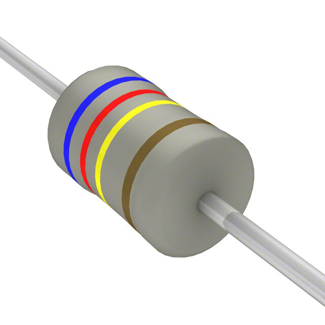
| 描述 | RES 0.02 OHM 1W 1% 2512 SMD |
| 产品分类 | |
| 品牌 | Yageo |
| 数据手册 | |
| 产品图片 |
|
| 产品型号 | PF2512FKF070R02L |
| rohs | 无铅 / 符合限制有害物质指令(RoHS)规范要求 |
| 产品系列 | PF |
| 产品目录绘图 |
|
| 产品目录页面 | |
| 供应商器件封装 | 2512 |
| 其它名称 | 311-0.02AGTR |
| 功率(W) | 1W |
| 包装 | 带卷 (TR) |
| 大小/尺寸 | 0.254" 长 x 0.128" 宽(6.45mm x 3.25mm) |
| 容差 | ±1% |
| 封装/外壳 | 2512(6432 公制) |
| 工作温度 | -55°C ~ 155°C |
| 成分 | 厚膜 |
| 标准包装 | 4,000 |
| 温度系数 | ±100ppm/°C |
| 特性 | 电流检测 |
| 特色产品 | http://www.digikey.com/product-highlights/cn/zh/yageo-pf1206-2512/995 |
| 电阻(Ω) | 0.02 |
| 端子数 | 2 |
| 高度 | 0.037"(0.95mm) |


PDF Datasheet 数据手册内容提取
DATA SHEET CURRENT SENSOR - LOWTCR PR/PF/PH series 5%, 2%, 1% sizes 0805/1206/2512/0815 RoHS compliant & Halogen free 3 0 0 2 6, 0 r. a M of e t a D s e d e s r e p u S 0 V. 1 1 0 2 1, 0 r e b m e v o N – n o ti a c cifi e p s t c u d o r P
Product specification 2 Chip Resistor Surface Mount PR/PF/PH SERIES 0805/1206/2512/0815 10 SCOPE ORDERING INFORMATION - GLOBAL PART NUMBER & 12NC This specification describes Both part numbers are identified by the series, size, tolerance, packing PR/PF/PH series current sensor - type, temperature coefficient, taping reel and resistance value. low TCR with lead-free terminations YYAAGGEEOO BBRRAANNDD oorrddeerriinngg ccooddee made by metal substrate. GLOBAL PART NUMBER (PREFERRED) PR/PF/PH XXXX X X X XX XXXX L APPLICATIONS (1) (2) (3) (4) (5) (6) (7) (cid:122) Power Management Applications (1) SIZE (cid:122) Current detection for Switching Power Supply 0805 / 1206 / 2512 / 0815 (cid:122) Computers, Consumer (2) TOLERANCE (cid:122) DC-DC Converter, Battery F = ±1% G = ±2% J = ±5% Pack, Charger, Adaptor (3) PACKAGING TYPE K = Embossed taping reel R = Paper taping reel FEATURES (cid:122) Halogen-free Epoxy (4) TEMPERATURE COEFFICIENT OF RESISTANCE (cid:122) RoHS compliant M = ±75 ppm/°C - Products with lead-free F = ±100 ppm/°C terminations meet RoHS G = ±200 ppm/°C requirements (5) TAPING REEL - Pb-glass contained in electrodes, resistor element and glass are 07 = 7 inch dia. Reel and standard power exempted by RoHS 7W = 7 inch dia. Reel and 2 x standard power (cid:122) Reduce environmentally 7T = 7 inch dia. Reel and 3 x standard power hazardous wastes (6) RESISTANCE VALUE (cid:122) High component and equipment reliability 1 mΩ to 50 mΩ (cid:122) None forbidden-materials used in There are 4~5 digits indicated the resistance value. Letter R is decimal point. products/production Detailed coding rules of resistance are shown in the table of “Resistance rule of (cid:122) Low resistances applied to global part number”. current sensing (7) DEFAULT CODE Letter L is the system default code for ordering only. (Note) Resistance rule ofglobal part ORDERING EXAMPLE number The ordering code of a PR2512 Resistance code rule Example chip resistor, value 0.005 X with ±1% tolerance, supplied in 7-inch 0RXXX 0R05 = 50 mΩ tape reel is: PR2512FKF070R005L. (1 to 50 mΩ) 0R001 = 1 mΩ NOTE 1. All our RSMD products are RoHS compliant. "LFP" of the internal 2D reel label mentions "Lead-Free Process" 2. On customized label, "LFP" or specific symbol printed and the optional "L" at the end of GLOBAL PART NUMBER / 12NC can be added (both are on customer request) www.yageo.com Nov 01, 2011 V.0
Product specification 3 Chip Resistor Surface Mount PR/PF/PH SERIES 0805/1206/2512/0815 10 PP HH YYCCOOMMPP BBRRAANNDD oorrddeerriinngg ccooddeess Both GLOBAL PART NUMBER (preferred) and 12NC (traditional) codes are acceptable to order Phycomp brand products. GLOBAL PART NUMBER (PREFERRED) For detailed information of GLOBAL PART NUMBER and ordering example, please refer to page 2. 1 2NC CODE 2322 XXX XXXXX L Last digit of 12NC (1) ( 2 ) (3) (4) Resistance decade (3) Last digit EMBOSSED (2) PAPER (units) (2) 0.001 to 0.005 X 0 START TOL. RESISTANCE SIZE TYPE IN (1) (%) RANGE TAPE ON REEL TAPE ON REEL Example: 0.005 X = 050 4,000 4,000 2512 MPRC221 2322 ±5% 0.001 to 0.005 Ω 762 94xxx - MPRC221 2322 ±1% 0.001 to 0.005 Ω 763 95xxx - (1) The resistors have a 12-digit ordering code starting with 2322. ORDERING EXAMPLE (2) The subsequent 4 or 5 digits indicate the resistor tolerance and The ordering code of a MPRC221 packaging. resistor, value 0.005 X with ±5% tolerance, supplied in tape of (3) The remaining 4 or 3 digits represent the resistance value with the 4,000 units per reel is: last digit indicating the multiplier as shown in the table of 232276294050L or “Last digit of 12NC”. PR2512FKF070R005L. (4) "L" is optional symbol (Note). NOTE 1. All our RSMD products are RoHS compliant. "LFP" of the internal 2D reel label mentions "Lead-Free Process" 2. On customized label, "LFP" or specific symbol printed and the optional "L" at the end of GLOBAL PART NUMBER / 12NC can be added (both are on customer request) www.yageo.com Nov 01, 2011 V.0
Product specification 4 Chip Resistor Surface Mount PR/PF/PH SERIES 0805/1206/2512/0815 10 MARKING PF0805 / PH0805 No marking ynsc107 Fig. 1 PF1206 / PH1206 / PR2512: Full range PF2512: R < 20 mΩ & R ≥ 20 mΩ with 2W 4 digits with top bar ynsc016 The “R” is used as a decimal point; the other 3 digits are significant Fig. 2 Value = 5 mΩ PF2512: R ≥ 20 mΩ with 1W 020 4 digits YNSC005 The “R” is used as a decimal point; the other 3 digits are significant Fig. 3 Value = 20 mΩ PF0815 4 digits: E24 series YNSC106 The “R” is used as a decimal point; the other 3 digits are significant Fig. 4 Value = 10 mΩ For further marking information, please refer to data sheet “Chip resistors marking”. www.yageo.com Nov 01, 2011 V.0
Product specification 5 Chip Resistor Surface Mount PR/PF/PH SERIES 0805/1206/2512/0815 10 CONSTRUCTION The resistors are constructed using outstanding TCR level material, which makes Yageo PR/PF/PH resistors excellent for current sensing application in battery charger circuit & DC-DC converter. The composition of the resistive material is adjusted to give the approximate required resistance and is covered with a protective coating, which printed with the resistance value. Finally, the three external terminations (Cu / Ni / matte Tin) are added, as shown in Fig. 4. OOuuttlliinneess For dimensions, please refer to Table 1 marking layer marking layer metal substrate protective coat protective coat end termination H inner electrode H end termination H inner electrode I2 protective coat I2 protective coat I2 protective coat rceesriasmtivice slauybesrt r(amteetal foil) ceramic substrate I1 resistive layer (cid:31) protective coat (metal foil) I1 marking I1 0 end termination W 001 0 0 W W 0 YNSC105 L L L PR series PF / PH s eries PF 0815 series Note: construction will be adjusted to resistance value (only for PFseries). Fig. 5 Chip resistor outlines DIMENSION Table 1 For outlines, please refer to Fig. 5 TYPE RESISTANCE RANGE L (mm) W (mm) H (mm) I (mm) I (mm) 1 2 PF/PH0805 0.01 to 0.05 Ω 2.03 ±0.25 1.27 ±0.25 0.33 ±0.12 0.38 ±0.25 0.38 ±0.25 PF/PH1206 0.01 to 0.05 Ω 3.20 ±0.25 1.60 ±0.25 0.60 ±0.25 0.50 ±0.25 0.65 ±0.25 PF0815 0.01 to 0.02 Ω 2.15 ±0.20 3.75 ±0.25 0.65 ±0.25 0.65 ±0.25 0.70 ±0.25 0.006 Ω 6.45 ±0.25 3.25 ±0.25 0.70 ±0.25 0.75 ±0.25 1.85 ±0.25 0.007 to 0.015 Ω 6.45 ±0.25 3.25 ±0.25 0.70 ±0.25 0.75 ±0.25 1.55 ±0.25 PF2512 0.02 to 0.05 Ω (1W) 6.45 ±0.25 3.25 ±0.25 0.70 ±0.25 1.30 ±0.25 0.75 ±0.25 0.02 to 0.05 Ω (2W) 6.45 ±0.25 3.25 ±0.25 0.70 ±0.25 0.75 ±0.25 1.30 ±0.25 0.001 to 0.002 Ω 6.40 ±0.20 3.20 ±0.20 0.75 ±0.15 1.20 ±0.20 1.20 ±0.20 PR2512 0.003 to 0.005 Ω 6.40 ±0.20 3.20 ±0.20 0.55 ±0.15 0.60 ±0.20 0.60 ±0.20 www.yageo.com Nov 01, 2011 V.0
Product specification 6 Chip Resistor Surface Mount PR/PF/PH SERIES 0805/1206/2512/0815 10 ELECTRICAL CHARACTERISTICS Table 2 TEMPERATURE COEFFICIENT OF TYPE POWER TOLERANCE RESISTANCE RANGE RESISTANCE PF0805 1/8 W, 1/4 W, 1/3 W 10 / 20 / 25 / 50 mΩ PH0805 1/2 W 10 / 20 / 25 / 50 mΩ PF1206 1/4 W, 1/2 W 10 / 15 / 20 / 25 / 30 / 40 / 50 mΩ ±100 ppm/°C, ±75 ppm/°C PH1206 1 W 10 / 15 / 20 / 25 / 30 / 40 / 50 mΩ ±1%, ±2%, ±5% PF0815 1/2W, 1W 10 /15 / 20 mΩ PF2512 1 W, 2W 6 / 7 / 8 / 10 / 15 / 20 / 25 / 33 / 50 mΩ 1 mΩ ≤ R ≤ 2 mΩ ±200 ppm/°C PR2512 1 W, 2W 1 / 2 / 3 / 4 / 5 mΩ 3 mΩ ≤ R ≤ 5 mΩ ±100 ppm/°C FOOTPRINT AND SOLDERING PROFILES For recommended footprint and soldering profiles, please refer to data sheet “Chip resistors mounting”. PACKING STYLE AND PACKAGING QUANTITY Table 3 Packing style and packaging quantity PACKING STYLE REEL DIMENSION PF / PH0805 PF / PH1206 PF0815 PF / PR2512 Paper taping reel (R) 7" (178 mm) 4,000 4,000 --- --- Embossed taping reel (K) 7" (178 mm) --- --- 4,000 4,000 NOTE 1. For paper/embossed tape and reel specification/dimensions, please refer to data sheet “Chip resistors packing”. www.yageo.com Nov 01, 2011 V.0
Product specification 7 Chip Resistor Surface Mount PR/PF/PH SERIES 0805/1206/2512/0815 10 FUNCTIONAL DESCRIPTION OOPPEERRAATTIINNGG TTEEMMPPEERRAATTUURREE RRAANNGGEE Range: –55°C to +155°C Pmax MRA632 (%Prated) PPOOWWEERR RRAATTIINNGG 100 Standard rated power at 70°C: 50 PF0805 = 1/8W PH0805 = 1/2W PF1206 = 1/4W 0 PH1206 = 1W −55 0 50 70 100 155 Tamb (°C) PF0815 = 1/2W PF2512 = 1W PR2512 = 1W Fig. 6 Maximum dissipation (P ) in percentage of rated power m ax For detail power value, please refer to Table 2. as a function of the oper ating ambient temperature (Tamb) RATED VOLTAGE The DC or AC (rms) continuous working voltage corresponding to the rated power is determined by the following formula: V = √(P X R) Where V = Continuous rated DC or AC (rms) working voltage (V) P = Rated power (W) R = Resistance value (X) www.yageo.com Nov 01, 2011 V.0
Product specification 8 Chip Resistor Surface Mount PR/PF/PH SERIES 0805/1206/2512/0815 10 TESTS AND REQUIREMENTS Table 4 Test condition, procedure and requirements TEST TEST METHOD PROCEDURE REQUIREMENTS Life/ MIL-STD-202G-method 108A 1,000 hours at 70±5 °C applied RCWV ±(1%+0.0005 Ω) Operational Life/ IEC 60115-1 4.25.1 1.5 hours on, 0.5 hour off, still air required Endurance JIS C 5202-7.10 High MIL-STD-202G-method 108A 1,000 hours at maximum operating temperature ±(1%+0.0005 Ω) Temperature IEC 60115-1 4.25.3 depending on specification, unpowered Exposure/ JIS C 5202-7.11 No direct impingement of forced air to the parts Endurance at Tolerances: 155±3 °C Upper Category Temperature Moisture MIL-STD-202G-method 106F Each temperature / humidity cycle is defined at 8 ±(0.5%+0.0005 Ω) Resistance IEC 60115-1 4.24.2 hours (method 106F), 3 cycles / 24 hours for 10d with 25 °C / 65 °C 95% R.H, without steps 7a & 7b, unpowered Parts mounted on test-boards, without condensation on parts Measurement at 24±2 hours after test conclusion Thermal Shock MIL-STD-202G-method 107G -55/+155 °C ±(0.5%+0.0005 Ω) Note: Number of cycles required is 300. Devices unmounted Maximum transfer time is 20 seconds. Dwell time is 15 minutes. Air – Air Short Time MIL-R-55342D-para 4.7.5 5 times of rated power for 5 seconds at room ±(0.5%+0.0005 Ω) Overload IEC60115-1 4.13 temperature No visible damage Board Flex/ IEC60115-1 4.33 Device mounted on PCB test board as described, ±(1%+0.05 Ω) Bending only 1 board bending required No visible damage Bending for 0805: 3 mm 1206/2512/other: 2 mm Holding time: minimum 60 seconds www.yageo.com Nov 01, 2011 V.0
Product specification 9 Chip Resistor Surface Mount PR/PF/PH SERIES 0805/1206/2512/0815 10 TEST TEST METHOD PROCEDURE REQUIREMENTS Solderability - Wetting IPC/JEDECJ-STD-002B test B Electrical Test not required Well tinned (≥95% covered) IEC 60068-2-58 Magnification 50X No visible damage SMD conditions: 1st step: method B, aging 4 hours at 155 °C dry heat 2nd step: leadfree solder bath at 245±3 °C Dipping time: 3±0.5 seconds - Leaching IPC/JEDECJ-STD-002B test D Leadfree solder, 260 °C, 30 seconds No visible damage IEC 60068-2-58 immersion time - Resistance to MIL-STD-202G-method 210F Condition B, no pre-heat of samples ±(0.5%+0.0005 Ω) Soldering Heat IEC 60068-2-58 Leadfree solder, 260 °C, 10 seconds No visible damage immersion time Procedure 2 for SMD: devices fluxed and cleaned with isopropanol www.yageo.com Nov 01, 2011 V.0
Product specification 10 Chip Resistor Surface Mount PR/PF/PH SERIES 0805/1206/2512/0815 10 REVISION HISTORY REVISION DATE CHANGE NOTIFICATION DESCRIPTION Version 0 Nov 01, 2011 - - New datasheet for current sensor - low TCR PR/PF/PH series sizes of 0805/1206/2512, 1%, 2% and 5% with lead-free terminations - Replace the pdf files: Pu-PRPF_PE_51_PbFree_L_1.pdf & PYu- PR_521_RoHS_L_2.pdf “ Yageo reserves all the rights for revising the content of this datasheet without further notification, as long as the products itself are unchanged. Any product change will be announced by PCN.” www.yageo.com Nov 01, 2011 V.0
Mouser Electronics Authorized Distributor Click to View Pricing, Inventory, Delivery & Lifecycle Information: Y ageo: PR2512FKF070R003L PR2512FKF070R005L PF2512FKF070R01L PF2512FKF070R02L PR2512FKG070R002L PR2512JKG070R001L PR2512FKG070R001L PF0805FRF7W0R022L PF1206FRM070R02L PF1206FRM7W0R01L PF2512FKF070R015L PF2512FKF070R033L PF2512FKF7W0R01L PF2512FKF7W0R02L PF2512FKF7W0R05L PF2512JKF070R01L PF2512JKM070R05L PR2512FKG7W0R002L PR2512JKG070R002L PR2512JKG7W0R002L PR2512FKF070R004L PF2512FKF7W0R007L PF1206FRF070R02L PF0805FRM470R01Z PR2512FKE7W0R012Z PF0805FRM7P0R02L PF0603FRE7T0R01Z PF1206FRF7W0R025L PF2512FKF7W0R033L PH1206FRF070R02L PR2512FKG7W0R001L PH1206FRF070R01A PR2512JKF070R003L PF1206FRF070R015L PF1206FRF7W0R02L PF0815FKF7W0R01Z PF0805FRM070R01L PF2512FKF7W0R006L PR2512FKF7W0R005L PF1206FRF7W0R05L PF0603FRM070R042Z PF2512FKF070R007L PF1206FRF7W0R01L PF2512FKM070R01Z PR2512FKF7W0R004L PF1206FRF070R01L PF2512FKM070R008L PH1206FRF070R01L PF0805FRM7W0R01L PF1206FKM7W0R008Z PF2512FKF070R008L PF1206FKM7W0R007Z PR2512FKF7W0R003L PF2512FKF070R006L PF0805FRM7W0R02L