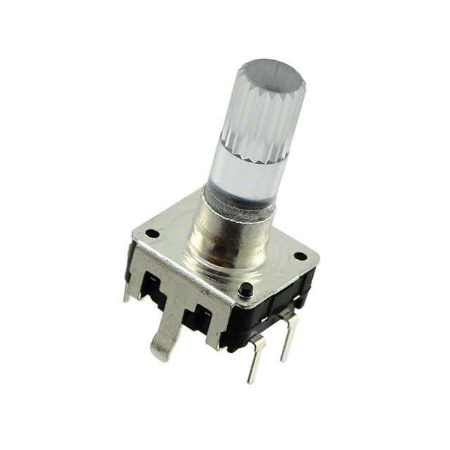
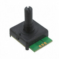
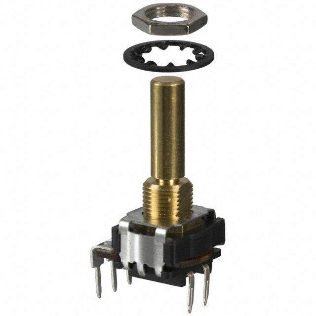
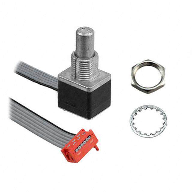
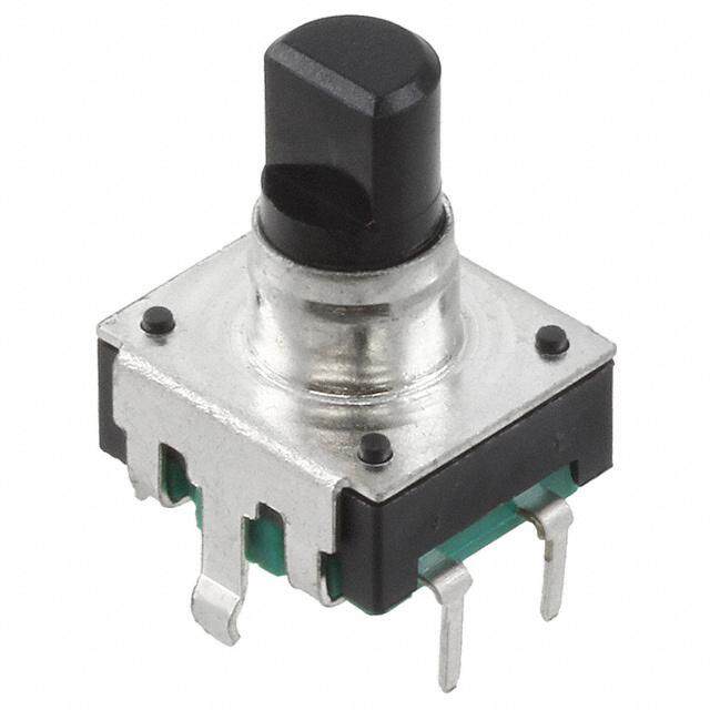
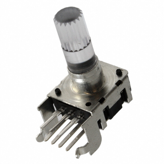
- 型号: PEL12D-2225S-S1024
- 制造商: Bourns
- 库位|库存: xxxx|xxxx
- 要求:
| 数量阶梯 | 香港交货 | 国内含税 |
| +xxxx | $xxxx | ¥xxxx |
查看当月历史价格
查看今年历史价格
PEL12D-2225S-S1024产品简介:
ICGOO电子元器件商城为您提供PEL12D-2225S-S1024由Bourns设计生产,在icgoo商城现货销售,并且可以通过原厂、代理商等渠道进行代购。 PEL12D-2225S-S1024价格参考。BournsPEL12D-2225S-S1024封装/规格:编码器, Rotary Encoder 机械 24 正交(增量) 垂直。您可以下载PEL12D-2225S-S1024参考资料、Datasheet数据手册功能说明书,资料中有PEL12D-2225S-S1024 详细功能的应用电路图电压和使用方法及教程。
| 参数 | 数值 |
| 产品目录 | |
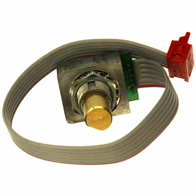
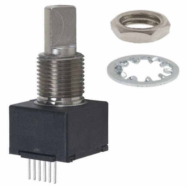
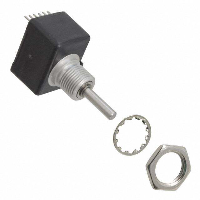
| 描述 | ENCODER MECH ILL 12MM BLU/ORN编码器 2pin Blue/Orange Knurled w/switch |
| 产品分类 | |
| 品牌 | Bourns |
| 产品手册 | |
| 产品图片 |
|
| rohs | 符合RoHS无铅 / 符合限制有害物质指令(RoHS)规范要求 |
| 产品系列 | Bourns PEL12D-2225S-S1024PEL12D |
| mouser_ship_limit | 该产品可能需要其他文件才能进口到中国。 |
| 数据手册 | |
| 产品型号 | PEL12D-2225S-S1024 |
| RoHS指令信息 | |
| 产品 | Mechanical Encoders |
| 产品种类 | |
| 其它名称 | PEL12D2225SS1024 |
| 内置开关 | 是 |
| 分辨率 | 24 PPR |
| 制动器数量 | 24 Detent |
| 单位重量 | 3 g |
| 商标 | Bourns |
| 大小/尺寸 | 12 mm |
| 套管材料 | - |
| 套管螺纹 | - |
| 安装类型 | PCB,通孔 |
| 安装风格 | Panel |
| 封装 | Tray |
| 工作温度范围 | - 10 C to + 70 C |
| 工厂包装数量 | 100 |
| 带开关 | Switch |
| 技术 | Rotary |
| 旋转寿命(最少次数) | 30K |
| 朝向 | 垂直 |
| 标准包装 | 100 |
| 棘爪 | 是 |
| 每转脉冲数 | 24 |
| 电压-电源 | - |
| 电源电压 | - |
| 端子类型 | PC 引脚 |
| 端接类型 | Through Hole |
| 类型 | Incremental |
| 系列 | PEC12D |
| 编码器类型 | 机械 |
| 致动器类型 | 6mm 直径滚花末端,发光式 |
| 衬套大小 | - |
| 轴直径 | 6 mm |
| 轴类型 | Knurled |
| 轴长度 | 25 mm |
| 输出 | Quadrature |
| 输出类型 | 正交(增量) |
| 通道数量 | 2 Channel |



- 商务部:美国ITC正式对集成电路等产品启动337调查
- 曝三星4nm工艺存在良率问题 高通将骁龙8 Gen1或转产台积电
- 太阳诱电将投资9.5亿元在常州建新厂生产MLCC 预计2023年完工
- 英特尔发布欧洲新工厂建设计划 深化IDM 2.0 战略
- 台积电先进制程称霸业界 有大客户加持明年业绩稳了
- 达到5530亿美元!SIA预计今年全球半导体销售额将创下新高
- 英特尔拟将自动驾驶子公司Mobileye上市 估值或超500亿美元
- 三星加码芯片和SET,合并消费电子和移动部门,撤换高东真等 CEO
- 三星电子宣布重大人事变动 还合并消费电子和移动部门
- 海关总署:前11个月进口集成电路产品价值2.52万亿元 增长14.8%

PDF Datasheet 数据手册内容提取
Features NT MPLIA ■ Compact design, long life and high HS CO reliability *Ro ■ Vertical and horizontal mount versions ■ Momentary switch ■ Dual LED design ■ Flatted and knurled shaft styles ■ Bushing and bushingless options PEL12D - 12 mm Encoder with Switch and Illuminated Shaft Electrical Characteristics Output .....................................................................................................................................................................................2-bit quadrature code Closed Circuit Resistance ...........................................................................................................................................................3 ohms maximum Contact Rating ..............................................................................................................................................................................0.5 mA @ 5 VDC Insulation Resistance ....................................................................................................................................................100 megohms @ 250 VDC Dielectric Withstanding Voltage Sea Level ................................................................................................................................................................................300 VAC minimum Electrical Travel ......................................................................................................................................................................................Continuous Contact Bounce (15 RPM).........................................................................................................................................................2.0 ms. maximum** RPM (Operating) ............................................................................................................................................................................100 maximum** Environmental Characteristics Operating Temperature Range .......................................................................................................................-10 °C to +70 °C (+14 °F to +158 °F) Storage Temperature Range ..........................................................................................................................-40 °C to +85 °C (-40 °F to +185 °F) Operating Humidity .....................................................................................................................................................................25 % to 85 % R.H. Rotational Life.....................................................................................................................................................................30,000 cycles minimum Switch Life ..........................................................................................................................................................................20,000 cycles minimum IP Rating ...........................................................................................................................................................................................................IP 40 Mechanical Characteristics Mechanical Angle ..........................................................................................................................................................................360 ° continuous Detent Torque ..................................................................................................................................................30 to 200 g-cm (0.42 to 2.77 oz.-in.) Running Torque .....................................................................................................................................................50 g-cm (0.69 oz.-in.) maximum Shaft Strength (Push) ......................................................................................................................................................................5 kgf (11.0 lbs.) Shaft Strength (Pull) ......................................................................................................................................................................10 kgf (22.0 lbs.) Weight ...............................................................................................................................................................................3 gm (0.1 oz.) maximum Terminals ..................................................................................................................................................................Printed circuit board terminals Soldering Condition Wave Soldering .....................................................................Sn95.5/Ag2.8/Cu0.7 solder with no-clean fl ux: 260 °C max. for 5 ± 1 seconds Hand Soldering ..................................................................................................................................................................Not recommended Hardware ...................................................................................One fl at washer and one mounting nut supplied with each encoder with bushing Switch Characteristics Switch Type .....................................................................................................................................................Contact Push ON Momentary SPST Power Rating (Resistive Load) ......................................................................................................................................................10 mA at 5 V DC Contact Resistance ............................................................................................................................................................................100 milliohms Switch Travel .................................................................................................................................................................................0.5 +0.0/-0.3 mm Switch Actuation Force .................................................................................................................................................450 ± 200 gf (15.9 ±7.0 oz.) How To Order PEL12D - 4 0 21 F - S 1 024 Model Terminal Confi guration 2 = Vertical Mount/Side Exit PC Pin 4 = Horizontal Mount/Rear Exit PC Pin Detent Option 0 = No Detents 2 = 24 Detents Standard Shaft Length Flatted: Knurled: 16 = 16.0 mm 26 = 26.0 mm 25 = 25.0 mm 18 = 18.5 mm 31 = 31.0 mm 21 = 21.0 mm Shaft Style F = Insulated Flatted Shaft S = Insulated Knurled Shaft (18 Teeth) G = Insulated Flatted Shaft w/Bushing*** T = Insulated Knurled Shaft (18 Teeth) w/Bushing Switch Confi guration S = Push Momentary Switch LED Color Dual: 1 = Blue/Orange 2 = Green/Red 3 = Blue/Green Resolution 024 = 24 Pulses per 360 ° Rotation *** Available in 18.5, 21 and 26 mm shaft lengths *RoHS Directive 2002/95/EC Jan. 27, 2003 including annex and RoHS Recast 2011/65/EU June 8, 2011. **Devices are tested using standard noise reduction fi lters. For optimum performance, designers should use noise reduction fi lters in their circuits. Specifi cations are subject to change without notice. The device characteristics and parameters in this data sheet can and do vary in different applications and actual device performance may vary over time. Users should verify actual device performance in their specifi c applications.
Applications Level control, tuning and timer settings in: ■ Audio-visual equipment ■ Consumer electric appliances ■ Musical instrumentation ■ Communications equipment PEL12D - 12 mm Encoder with Switch and Illuminated Shaft Product Dimensions PEL12D-4xxxS-Sxxxx (Horizontal Mount w/Dual LED & Switch, Knurled Shaft) MOUNTING SURFACE 25.0 14.0 (.984) 7.0 18.0 (.551) 13.2 ± 0.1 (.276) (.709) 12.4 (.520 ± .004) (.488) 6.0 ± 0.1 4(. 00P.3L81C)S. (.00.132)(.21.194) (.003.81) (.51.907) (.277.06) 0SS.5WT +RI0TO/CK-0HE.3 (.83.223) (.(2.30267. 09± ±±.0 0.00.410)4) (.0D13I.A09. ++40. 0P.20L/8-C/0-S0.) (.020 +0/-.012) 2 PLCS. 2.0 ± 0.1 7.0 ± 0.1 4 3 2 1 2.1 +0.1/-0 (.083 +.004/-0) (.079 ± .004) (.276 ± .004) 10.2 13.2 18 TEETH (.402) (.520) 7.5 ± 0.1 (.00.132) 6.8 DIA. (.62.306) (.295 ± .004) (.027.09 ++0.0.10/4-/0-0) (.268) DIA. 2 PLCS. 2.8 A C B A C B (.110) 5.0 5.0 ± 0.1 1.1 +0.2/-0 (.197) (.197 ± .004) (.043 +.008/-0) DIA. 3 PLCS. PEL12D-4xxxF-Sxxxx (Horizontal Mount w/Dual LED & Switch, Flatted Shaft) MOUNTING SURFACE LM (1.545.01) L1 LM 7.0 (.276) L1 12.4 3 16 SWITCH (.488) (.118) (.630) 2.9 5.0 1.5 STROKE 0.3 (.114) 0.8 (.197) (.591) (.002.50 ++00//--0.0.312) (.382.23) 5 18.5 (.012) (.031) (.197) (.728) 0.5 7 21 (.020) 2.0 ± 0.1 (.276) (.827) (.079 ± .004) 10.2 13.2 12 26 (.402) (.520) (.472) (1.024) 0.3 (.012) 6.8 4.5 ± 0.05 12 31 (.268) (.177 ± .002) (.472) (1.220) 2.8 DIA. 6.0 ± 0.1 A C B (.110) DIA.(.236 ± .004) 5.0 (.197) MM DIMENSIONS: (INCHES) Dual LED Circuit TOLERANCES: UNDER10.0 = ±0.3 10.0 ~ 100 = ±0.5 (.394) (±.012) (.394 ~ 3.937) (±.020) 4 (+) 3 (+) 2 (-) 1 Specifi cations are subject to change without notice. The device characteristics and parameters in this data sheet can and do vary in different applications and actual device performance may vary over time. Users should verify actual device performance in their specifi c applications.
PEL12D - 12 mm Encoder with Switch and Illuminated Shaft Product Dimensions PEL12D-2xxxS-Sxxxx (Vertical Mount w/Dual LED & Switch, Knurled Shaft) MOUNTING SURFACE 25.0 (.984) 4.5 ± 0.1 7.0 18.0 12.4 (.177 ± .004) (.276) (.709) 3.1 ± 0.1 (.488) 2.0 +0.1/-0 (.20.958) 0.8 (.51.907) 7.0 SSWTRITOCKHE (.83.125) (.0729 P+L.0C0S4./-0) (.122 ± .004) (.031) (.276) (.002.50 ++00//--0.0.312) (.263.06 ±± 0.0.104) (.013.09 ++0.0.20/8-/0-0) DIA. 4 PLCS. 5.0 ± 0.1 18 TEETH (1.400.22) (1.532.20) 10.8 ± 0.1 4 BC (.197 ± .004) 3 (.425 ± .004) 10.0 6.0 2 A (.394) 6.8 DIA. (.236) 1 (.268) DIA. 1.1 +0.2/-0 (.043 +.008/-0) DIA. 3 PLCS. 2.0 ± 0.1 (.079 ± .004) 3.5 4 PLCS. (.138) A C B 2.0 +0.1/-0 0.8 2.0 10.0 (.079 +.004/-0) 2.1 +0.1/-0 (.031) (.079) 6.1 (.394) 2 PLCS. (.0823 P+L.0C0S4./-0) (.240) PEL12D-2xxxF-Sxxxx (Vertical Mount w/Dual LED & Switch, Flatted Shaft) MOUNTING SURFACE LM 7.0 L1 LM L1 12.4 (.276) SWITCH (.488) 3 16 2.5 5.0 1.5 STROKE (.098) (.197) (.591) 0.5 +0/-0.3 8.2 (.118) (.630) 0.8 (.020 +0/-.012) (.315) (.031) 5 18.5 0.5 (.197) (.728) (.020) 7 21 10.2 13.2 (.276) (.827) (.402) (.520) 12 26 10.0 (.472) (1.024) (.394) 6.8 4.5 ± 0.05 (.268) (.177 ± .002) 12 31 DIA. 6.0 ± 0.1 (.472) (1.220) DIA. (.236 ± .004) 3.5 A C B (.138) 10.0 2.0 (.394) (.079) 6.1 (.240) MM DIMENSIONS: (INCHES) TOLERANCES: UNDER10.0 = ±0.3 10.0 ~ 100 = ±0.5 (.394) (±.012) (.394 ~ 3.937) (±.020) Specifi cations are subject to change without notice. The device characteristics and parameters in this data sheet can and do vary in different applications and actual device performance may vary over time. Users should verify actual device performance in their specifi c applications.
PEL12D - 12 mm Encoder with Switch and Illuminated Shaft Product Dimensions Quadrature Output Table PEL12D-4xxxT-Sxxxx (Horizontal Mount w/Dual LED & Switch, Knurled Shaft w/Bushing) CW 25.0 (.984) OFF 7.5 17.5 A Signal ON (.295) (.689) 7.0 7.0 (.276) (.276) B Signal 0.3 (.012) D CCW 18 TEETH 0.75 6.0 DIA. Suggested Filter Circuit M9 X (.030) (.236) 5 VDC PEL12D-4xxxG-Sxxxx (Horizontal Mount w/Dual LED & Switch, Flatted Shaft w/Bushing) 10K OHMS 10K OHMS 10K OHMS 10K OHMS LM L2 L1 LM TERMINAL A TERMINAL B L1 5.0 5 11 18.5 0.01 μF 0.01 μF (.199) L2 (.197) (.433) (.728) ENCODER 7 13.5 21 TERMINAL C (.276) (.532) (.827) 12 18.5 26 (.472) (.728) (1.024) LED Terminal Decoder 0.75 M9 X (.030) Code Color Terminals DIMENSIONS: MM 1 Blue / Orange ➀ ➁ / ➀ ➂ (INCHES) 2 Green / Red ➀ ➁ ➀ ➂ / TOLERANCES: 3 Blue / Green ➀ ➁ / ➀ ➂ UNDER10.0 = ±0.3 10.0 ~ 100 = ±0.5 (.394) (±.012) (.394 ~ 3.937) (±.020) LED Characteristics (Dual) DC Forward Voltage (V) Power Forward Dissipation Current LED Color (mW) (mA) Typ. Max. Blue/ Blue 105 30 3.3 4.0 Asia-Pacifi c: Orange Orange 75 30 2.1 2.5 Tel: +886-2 2562-4117 Fax: +886-2 2562-4116 Green/ Green 120 30 3.2 4.0 Red Red 75 30 1.95 2.5 EMEA: Tel: +36 88 520 390 Blue/ Blue 120 30 3.3 4.0 Fax: +36 88 520 211 Green Green 120 30 3.2 4.0 The Americas: Tel: +1-951 781-5500 Red/ Red 75 30 1.95 2.5 Fax: +1-951 781-5700 Green Green 120 30 3.2 4.0 www.bourns.com Notes: Reverse Current: 10 μA Reverse Voltage: 5 VDC REV. 03/15 Test Condition (IF): 20 mA Specifi cations are subject to change without notice. The device characteristics and parameters in this data sheet can and do vary in different applications and actual device performance may vary over time. Users should verify actual device performance in their specifi c applications.
 Datasheet下载

