ICGOO在线商城 > PCM1789TPWRQ1
- 型号: PCM1789TPWRQ1
- 制造商: Texas Instruments
- 库位|库存: xxxx|xxxx
- 要求:
| 数量阶梯 | 香港交货 | 国内含税 |
| +xxxx | $xxxx | ¥xxxx |
查看当月历史价格
查看今年历史价格
PCM1789TPWRQ1产品简介:
ICGOO电子元器件商城为您提供PCM1789TPWRQ1由Texas Instruments设计生产,在icgoo商城现货销售,并且可以通过原厂、代理商等渠道进行代购。 提供PCM1789TPWRQ1价格参考以及Texas InstrumentsPCM1789TPWRQ1封装/规格参数等产品信息。 你可以下载PCM1789TPWRQ1参考资料、Datasheet数据手册功能说明书, 资料中有PCM1789TPWRQ1详细功能的应用电路图电压和使用方法及教程。
| 参数 | 数值 |
| 产品目录 | 集成电路 (IC) |
| 描述 | IC DAC 24BIT STER 192KHZ 24TSSOP |
| 产品分类 | |
| 品牌 | Texas Instruments |
| 数据手册 | |
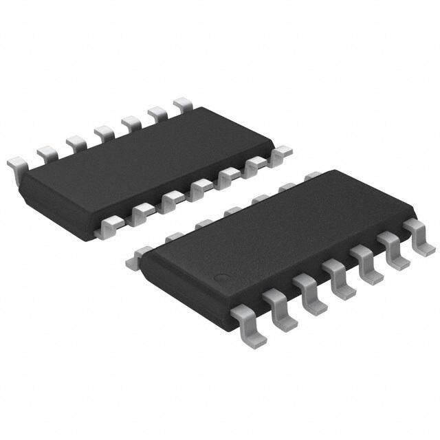
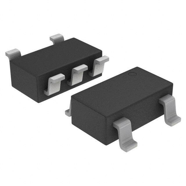
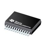
| 产品图片 |
|
| 产品型号 | PCM1789TPWRQ1 |
| rohs | 无铅 / 符合限制有害物质指令(RoHS)规范要求 |
| 产品系列 | 自动,AEC-Q100 |
| 位数 | 24 |
| 供应商器件封装 | 24-TSSOP |
| 其它名称 | 296-28413-1 |
| 包装 | 剪切带 (CT) |
| 安装类型 | 表面贴装 |
| 封装/外壳 | 24-TSSOP(0.173",4.40mm 宽) |
| 工作温度 | -40°C ~ 85°C |
| 建立时间 | - |
| 数据接口 | I²C, I²S, 串行, SPI™ |
| 标准包装 | 1 |
| 电压源 | 模拟和数字 |
| 转换器数 | 2 |
| 输出数和类型 | 4 电压,单极 |
| 采样率(每秒) | 8k ~ 192k |

PDF Datasheet 数据手册内容提取
PCM1789-Q1 Burr-Brown Audio www.ti.com SBAS546–MARCH2011 24-Bit, 192-kHz Sampling, Enhanced Multi-Level ΔΣ, Stereo, Audio Digital-to-Analog Converter CheckforSamples:PCM1789-Q1 FEATURES – AudioI/FFormatSelect:I2S,Left-Justified 1 • QualifiedforAutomotiveApplications – DigitalDe-EmphasisFilter:44.1kHz 234 • EnhancedMulti-LevelDelta-SigmaDAC: • AnalogMutebyClockHaltDetection – HighPerformance:Differential,f =48kHz • ExternalResetPin S – THD+N: –94dB • PowerSupplies: – SNR:113dB – 5VforAnalogand3.3VforDigital – DynamicRange:113dB • Package:TSSOP-24 – SamplingRate:8kHzto192kHz • OperatingTemperatureRange: – SystemClock:128f ,192f ,256f ,384f , – –40°Cto+105°C S S S S 512f ,768f ,1152f S S S APPLICATIONS – DifferentialVoltageOutput:8V PP • AVReceivers – AnalogLow-PassFilterIncluded • CarAudioExternalAmplifiers – 4x/8xOversamplingDigitalFilter: • CarAudioAVNApplications – PassbandRipple:±0.0018dB – StopBandAttenuation:–75dB DESCRIPTION – ZeroFlags(16-/20-/24-Bits) The PCM1789-Q1 is a high-performance, single-chip, • FlexibleAudioInterface: 24-bit, stereo, audio digital-to-analog converter (DAC) – I/FFormat:I2S™,Left-/Right-Justified,DSP with differential outputs. The two-channel, 24-bit DAC employs an enhanced multi-level, delta-sigma (ΔΣ) – DataLength:16,20,24,32Bits modulator, and supports 8 kHz to 192 kHz sampling • FlexibleModeControl: rates and a 16-/20-/24-/32-bit width digital audio input – 3-WireSPI™,2-WireI2C™-Compatible word on the audio interface. The audio interface of SerialControlInterface,or PCM1789-Q1 supports a 24-bit, DSP format in addition to I2S, left-justified, and right-justified HardwareControl formats. – ConnectUpTo4DevicesonOneSPIBus • MultiFunctionsviaSPIorI2CI/F: The PCM1789-Q1 can be controlled through a three-wire, SPI-compatible or two-wire, – AudioI/FFormatSelect:I2S,Left-Justified, I2C-compatible serial interface in software, which Right-Justified,DSP provides access to all functions including digital – DigitalAttenuationandSoftMute attenuation, soft mute, de-emphasis, and so forth. Also, hardware control mode provides two – DigitalDe-Emphasis:32kHz,44.1kHz, user-programmable functions through two control 48kHz pins. The PCM1789-Q1 is available in a 24-pin – DataPolarityControl TSSOPpackage. – Power-SaveMode • MultiFunctionsviaHardwareControl: 1 Pleasebeawarethatanimportantnoticeconcerningavailability,standardwarranty,anduseincriticalapplicationsofTexas Instrumentssemiconductorproductsanddisclaimerstheretoappearsattheendofthisdatasheet. SPIisatrademarkofMotorola,Inc. 2I2S,I2CaretrademarksofNXPSemiconductors. 3 Allothertrademarksarethepropertyoftheirrespectiveowners. 4 PRODUCTIONDATAinformationiscurrentasofpublicationdate. Copyright©2011,TexasInstrumentsIncorporated Products conform to specifications per the terms of the Texas Instruments standard warranty. Production processing does not necessarilyincludetestingofallparameters.
PCM1789-Q1 SBAS546–MARCH2011 www.ti.com This integrated circuit can be damaged by ESD. Texas Instruments recommends that all integrated circuits be handled with appropriateprecautions.Failuretoobserveproperhandlingandinstallationprocedurescancausedamage. ESDdamagecanrangefromsubtleperformancedegradationtocompletedevicefailure.Precisionintegratedcircuitsmaybemore susceptibletodamagebecauseverysmallparametricchangescouldcausethedevicenottomeetitspublishedspecifications. ORDERINGINFORMATION(1) T PACKAGE ORDERABLEPART TOP-SIDEMARKING A –40°Cto105°C TSSOP-24–PW Reelof2000 PCM1789TPWRQ1 PCM1789T (1) ForthemostcurrentpackageandorderinginformationseethePackageOptionAddendumattheendofthisdocument,orseetheTI websiteatwww.ti.com. ABSOLUTE MAXIMUM RATINGS(1) Overoperatingfree-airtemperaturerange(unlessotherwisenoted). PARAMETER PCM1789-Q1 UNIT VCC1,VCC2 –0.3to+6.5 V Supplyvoltage VDD –0.3to+4.0 V Groundvoltagedifferences:AGND1,AGND2,DGND ±0.1 V Supplyvoltagedifferences:VCC1,VCC2 ±0.1 V RST,ADR5,MS,MC,MD,SCKI,AMUTEI –0.3to+6.5 V Digitalinputvoltage BCK,LRCK,DIN,MODE,ZERO1,ZERO2 –0.3to(VDD+0.3)<+4.0 V Analoginputvoltage:VCOM,VOUTL±,VOUTR± –0.3to(VCC+0.3)<+6.5 V Inputcurrent(allpinsexceptsupplies) ±10 mA Ambienttemperatureunderbias –40to+125 °C Storagetemperature –55to+150 °C Junctiontemperature +150 °C Leadtemperature(soldering,5s) +260 °C Packagetemperature(IRreflow,peak) +260 °C (1) StressesbeyondthoselistedunderAbsoluteMaximumRatingsmaycausepermanentdamagetothedevice.Thesearestressratings onlyandfunctionaloperationofthedeviceattheseoranyotherconditionsbeyondthoseindicatedunderRecommendedOperating Conditionsisnotimplied.Exposuretoabsolute-maximum-ratedconditionsforextendedperiodsmayaffectdevicereliability. RECOMMENDED OPERATING CONDITIONS Overoperatingfree-airtemperaturerange(unlessotherwisenoted). PCM1789-Q1 PARAMETER MIN TYP MAX UNIT Analogsupplyvoltage,VCC 4.5 5.0 5.5 V Digitalsupplyvoltage,VDD 3.0 3.3 3.6 V DigitalInterface LVTTL-compatible Samplingfrequency,LRCK 8 192 kHz Digitalinputclockfrequency Systemclockfrequency,SCKI 2.048 36.864 MHz Analogoutputvoltage Differential 8 V PP Toac-coupledGND 5 kΩ Analogoutputloadresistance Todc-coupledGND 15 kΩ Analogoutputloadcapacitance 50 pF Digitaloutputloadcapacitance 20 pF Operatingfree-airtemperature PCM1789-Q1consumergrade –40 25 105 °C 2 SubmitDocumentationFeedback Copyright©2011,TexasInstrumentsIncorporated ProductFolderLink(s):PCM1789-Q1
PCM1789-Q1 www.ti.com SBAS546–MARCH2011 ELECTRICAL CHARACTERISTICS: Digital Input/Output AllspecificationsatT =+25°C,VCC1=VCC2=5V,VDD=3.3V,f =48kHz,SCKI=512f ,24-bitdata,andSampling A S S mode=Auto,unlessotherwisenoted. PCM1789-Q1 PARAMETER TESTCONDITIONS MIN TYP MAX UNIT DATAFORMAT Audiodatainterfaceformat I2S,LJ,RJ,DSP Audiodatawordlength 16,20,24,32 Bits Audiodataformat MSBfirst,twoscomplement Samplingfrequency f 8 48 192 kHz S 128f ,192f ,256f , Systemclockfrequency S S S 2.048 36.864 MHz 384f ,512f ,768f ,1152f S S S S INPUTLOGIC V (1) (2) 2.0 VDD VDC IH Inputlogiclevel V (1) (2) 0.8 VDC IL V (3) (4) 2.0 5.5 VDC IH Inputlogiclevel V (3) (4) 0.8 VDC IL I (2) (3) V =VDD ±10 μA IH IN Inputlogiccurrent I (2) (3) V =0V ±10 μA IL IN I (1) (4) V =VDD +65 +100 μA IH IN Inputlogiccurrent I (1) (4) V =0V ±10 μA IL IN OUTPUTLOGIC V (5) I =–4mA 2.4 VDC OH OUT Outputlogiclevel V (5) (6) I =+4mA 0.4 VDC OL OUT REFERENCEOUTPUT 0.5× VCOMoutputvoltage V VCC1 VCOMoutputimpedance 7.5 kΩ AllowableVCOMoutputsource/sinkcurrent 1 μA (1) BCKandLRCK(Schmitttriggerinputwith50-kΩtypicalinternalpull-downresistor). (2) DIN(Schmitttriggerinput). (3) SCKI,ADR5/ADR1/RSV,MC/SCL/FMT,MD/SDA/DEMP,andAMUTEI(Schmitttriggerinput,5-Vtolerant). (4) RSTandMS/ADR0/RSV(Schmitttriggerinputwith50-kΩtypicalinternalpull-downresistor,5-Vtolerant). (5) ZERO1andZERO2. (6) AMUTEOandSDA(I2Cmode,open-drainlowoutput). Copyright©2011,TexasInstrumentsIncorporated SubmitDocumentationFeedback 3 ProductFolderLink(s):PCM1789-Q1
PCM1789-Q1 SBAS546–MARCH2011 www.ti.com ELECTRICAL CHARACTERISTICS: DAC AllspecificationsatT =+25°C,VCC1=VCC2=5V,VDD=3.3V,f =48kHz,SCKI=512f ,24-bitdata,andSampling A S S mode=Auto,unlessotherwisenoted. PCM1789-Q1 PARAMETER TESTCONDITIONS MIN TYP MAX UNIT RESOLUTION 16 24 Bits DCACCURACY Gainmismatchchannel-to-channel ±2.0 ±6.0 %ofFSR Gainerror ±2.0 ±6.0 %ofFSR Bipolarzeroerror ±1.0 %ofFSR DYNAMICPERFORMANCE(1)(2) f =48kHz –94 –88 dB S Totalharmonicdistortion+noise THD+N V =0dB f =96kHz –94 dB OUT S f =192kHz –94 dB S f =48kHz,EIAJ,A-weighted 106 113 dB S Dynamicrange f =96kHz,EIAJ,A-weighted 113 dB S f =192kHz,EIAJ,A-weighted 113 dB S f =48kHz,EIAJ,A-weighted 106 113 dB S Signal-to-noiseratio SNR f =96kHz,EIAJ,A-weighted 113 dB S f =192kHz,EIAJ,A-weighted 113 dB S f =48kHz 103 109 dB S Channelseparation f =96kHz 109 dB S f =192kHz 108 dB S ANALOGOUTPUT Outputvoltage Differential 1.6×VCC1 V PP Centervoltage 0.5×VCC1 V Toac-coupledGND(3) 5 kΩ Loadimpedance Todc-coupledGND(3) 15 kΩ f=20kHz –0.04 dB LPFfrequencyresponse f=44kHz –0.18 dB DIGITALFILTERPERFORMANCEWITHSHARPROLL-OFF ExceptSCKI=128f and192f 0.454×f Hz S S S Passband(single,dual) SCKI=128f and192f 0.432×f Hz S S S Passband(quad) 0.432×f Hz S ExceptSCKI=128f and192f 0.546×f Hz S S S Stopband(single,dual) SCKI=128f and192f 0.569×f Hz S S S Stopband(quad) 0.569×f Hz S Passbandripple <0.454×f ,0.432×f ±0.0018 dB S S Stopbandattenuation >0.546×f ,0.569×f –75 dB S S (1) IndifferentialmodeatVOUTx±pin,f =1kHz,usingAudioPrecisionSystemII,Averagemodewith20-kHzLPFand400-HzHPF. OUT (2) f =48kHz:SCKI=512f (single),f =96kHz:SCKI=256f (dual),f =192kHz:SCKI=128f (quad). S S S S S S (3) Allowableminimuminputresistanceofdifferential-to-single-endedconverterwithD-to-Sgain=Giscalculatedas(1+2G)/(1+G)×5k forac-coupled,and(1+0.9G)/(1+G)×15kfordc-coupledconnection;refertoFigure38andFigure39. 4 SubmitDocumentationFeedback Copyright©2011,TexasInstrumentsIncorporated ProductFolderLink(s):PCM1789-Q1
PCM1789-Q1 www.ti.com SBAS546–MARCH2011 ELECTRICAL CHARACTERISTICS: DAC (continued) AllspecificationsatT =+25°C,VCC1=VCC2=5V,VDD=3.3V,f =48kHz,SCKI=512f ,24-bitdata,andSampling A S S mode=Auto,unlessotherwisenoted. PCM1789-Q1 PARAMETER TESTCONDITIONS MIN TYP MAX UNIT DIGITALFILTERPERFORMANCEWITHSLOWROLL-OFF Passband 0.328×f Hz S Stopband 0.673×f Hz S Passbandripple <0.328×f ±0.0013 dB S Stopbandattenuation >0.673×f –75 dB S DIGITALFILTERPERFORMANCE ExceptSCKI=128f and192f 28/f sec S S S Groupdelaytime(single,dual) SCKI=128f and192f 19/f sec S S S Groupdelaytime(quad) 19/f sec S De-emphasiserror ±0.1 dB ELECTRICAL CHARACTERISTICS: Power-Supply Requirements AllspecificationsatT =+25°C,VCC1=VCC2=5V,VDD=3.3V,f =48kHz,SCKI=512f ,24-bitdata,andSampling A S S mode=Auto,unlessotherwisenoted. PCM1789-Q1 PARAMETER TESTCONDITIONS MIN TYP MAX UNIT POWER-SUPPLYREQUIREMENTS VCC1/2 4.5 5.0 5.5 VDC Voltagerange VDD 3.0 3.3 3.6 VDC f =48kHz 19 28 mA S I f =192kHz 19 mA CC S Fullpower-down(1) 170 μA Supplycurrent f =48kHz 18 30 mA S I f =192kHz 22 mA DD S Fullpower-down(1) 60 μA f =48kHz 154 239 mW S Powerdissipation f =192kHz 168 mW S Fullpower-down(1) 1.05 mW TEMPERATURERANGE Operatingtemperature PCM1789-Q1consumergrade –40 +85 °C Thermalresistance θ TSSOP-24 115 °C/W JA (1) SCKI,BCK,andLRCKstopped. Copyright©2011,TexasInstrumentsIncorporated SubmitDocumentationFeedback 5 ProductFolderLink(s):PCM1789-Q1
PCM1789-Q1 SBAS546–MARCH2011 www.ti.com PIN CONFIGURATION PWPACKAGE TSSOP-24 (TOPVIEW) LRCK 1 24 ADR5/ADR1/RSV BCK 2 23 MS/ADR0/RSV DIN 3 22 MC/SCL/FMT RST 4 21 MD/SDA/DEMP SCKI 5 20 MODE VDD 6 19 ZERO1 PCM1789 DGND 7 18 ZERO2/AMUTEO VCC1 8 17 AMUTEI VCOM 9 16 VCC2 AGND1 10 15 AGND2 VOUTL- 11 14 VOUTR- VOUTL+ 12 13 VOUTR+ TERMINALFUNCTIONS TERMINAL PULL- 5-V NAME PIN I/O DOWN TOLERANT DESCRIPTION LRCK 1 I Yes No Audiodatawordclockinput BCK 2 I Yes No Audiodatabitclockinput DIN 3 I No No Audiodatainput RST 4 I Yes Yes Resetandpower-downcontrolinputwithactivelow SCKI 5 I No Yes Systemclockinput VDD 6 — — — Digitalpowersupply,+3.3V DGND 7 — — — Digitalground VCC1 8 — — — Analogpowersupply1,+5V VCOM 9 — — — Voltagecommondecoupling AGND1 10 — — — Analogground1 VOUTL– 11 O No No NegativeanalogoutputfromDACleftchannel VOUTL+ 12 O No No PositiveanalogoutputfromDACleftchannel VOUTR+ 13 O No No PositiveanalogoutputfromDACrightchannel VOUTR– 14 O No No NegativeanalogoutputfromDACrightchannel AGND2 15 — — — Analogground2 VCC2 16 — — — Analogpowersupply2,+5V AMUTEI 17 I No Yes Analogmutecontrolinputwithactivelow ZERO2/AMUTEO 18 O No No Zerodetectflagoutput2/Analogmutecontroloutput(1)withactivelow ZERO1 19 O No No Zerodetectflagoutput1 Controlportmodeselection.TiedtoVDD:SPI,ADR6=1,pull-up:SPI, MODE 20 I No No ADR6=0,pull-down:H/Wautomode,tiedtoDGND:I2C InputdataforSPI,dataforI2C(1),de-emphasiscontrolforhardware MD/SDA/DEMP 21 I/O No Yes controlmode MC/SCL/FMT 22 I No Yes ClockforSPI,clockforI2C,formatselectforhardwarecontrolmode ChipSelectforSPI,addressselect0forI2C,reserve(setlow)for MS/ADR0/RSV 23 I Yes Yes hardwarecontrolmode Addressselect5forSPI,addressselect1forI2C,reserve(setlow)for ADR5/ADR1/RSV 24 I No Yes hardwarecontrolmode (1) Open-drainconfigurationinoutmode. 6 SubmitDocumentationFeedback Copyright©2011,TexasInstrumentsIncorporated ProductFolderLink(s):PCM1789-Q1
PCM1789-Q1 www.ti.com SBAS546–MARCH2011 FUNCTIONAL BLOCK DIAGRAM BCK VOUTL+ DAC LRCK Audio Interface Interpolation (Left Ch) DIN Filter VOUTL- Digital Attenuation VOUTR+ Digital Mute DAC De-Emphasis (Right Ch) SCKI Clock Manager VOUTR- VCOM VCOM MODE ADR5/ADR1/RSV VCC1 MS/ADR0/RSV AGND1 MC/SCL/FMT Control Interface Power Supply VCC2 MD/SDA/DEMP (SPI/I2C/Hardware) and RST Common Voltage AGND2 AMUTEI VDD ZERO1 ZERO2/AMUTEO DGND Copyright©2011,TexasInstrumentsIncorporated SubmitDocumentationFeedback 7 ProductFolderLink(s):PCM1789-Q1
PCM1789-Q1 SBAS546–MARCH2011 www.ti.com TYPICAL CHARACTERISTICS: Digital Filter AllspecificationsatT =+25°C,VCC1=VCC2=5V,VDD=3.3V,f =48kHz,SCKI=512f ,24-bitdata,andSampling A S S mode=Auto,unlessotherwisenoted. FREQUENCYRESPONSE FREQUENCYRESPONSEPASSBAND (SingleRate) (SingleRate) 0 0.010 Sharp Sharp 0.008 -20 Slow Slow 0.006 -40 0.004 B) B) e (d -60 e (d 0.002 ud ud 0 mplit -80 mplit -0.002 A A -100 -0.004 -0.006 -120 -0.008 -140 -0.010 0 1 2 3 4 0 0.1 0.2 0.3 0.4 0.5 Normalized Frequency (f ) Normalized Frequency (f ) S S Figure1. Figure2. FREQUENCYRESPONSE FREQUENCYRESPONSEPASSBAND (DualRate) (DualRate) 0 0.010 Sharp Sharp 0.008 -20 Slow Slow 0.006 -40 0.004 B) B) e (d -60 e (d 0.002 ud ud 0 mplit -80 mplit -0.002 A A -100 -0.004 -0.006 -120 -0.008 -140 -0.010 0 1 2 3 4 0 0.1 0.2 0.3 0.4 0.5 Normalized Frequency (f ) Normalized Frequency (f ) S S Figure3. Figure4. FREQUENCYRESPONSE FREQUENCYRESPONSEPASSBAND (QuadRate) (QuadRate) 0 0.010 Sharp Sharp 0.008 -20 Slow Slow 0.006 -40 0.004 B) B) e (d -60 e (d 0.002 ud ud 0 mplit -80 mplit -0.002 A A -100 -0.004 -0.006 -120 -0.008 -140 -0.010 0 0.5 1.0 1.5 2.0 0 0.1 0.2 0.3 0.4 0.5 Normalized Frequency (f ) Normalized Frequency (f ) S S Figure5. Figure6. 8 SubmitDocumentationFeedback Copyright©2011,TexasInstrumentsIncorporated ProductFolderLink(s):PCM1789-Q1
PCM1789-Q1 www.ti.com SBAS546–MARCH2011 TYPICAL CHARACTERISTICS: Digital De-Emphasis Filter AllspecificationsatT =+25°C,VCC1=VCC2=5V,VDD=3.3V,f =48kHz,SCKI=512f ,24-bitdata,andSampling A S S mode=Auto,unlessotherwisenoted. DE-EMPHASISCHARACTERISTIC DE-EMPHASISCHARACTERISTIC (f =48kHz) (f =44.1kHz) S S 0 0 -1 -1 -2 -2 -3 -3 B) B) e (d -4 e (d -4 ud -5 ud -5 mplit -6 mplit -6 A A -7 -7 -8 -8 -9 -9 -10 -10 0 2 4 6 8 10 12 14 16 18 20 22 0 2 4 6 8 10 12 14 16 18 20 Frequency (kHz) Frequency (kHz) Figure7. Figure8. DE-EMPHASISCHARACTERISTIC (f =32kHz) ANALOGFILTERCHARACTERISTIC S 0 0 -1 -2 -10 -3 B) B) e (d -4 e (d -20 ud -5 ud mplit -6 mplit -30 A A -7 -8 -40 -9 -10 -50 0 2 4 6 8 10 12 14 1k 10k 100k 1M 10M Frequency (kHz) Frequency (Hz) Figure9. Figure10. Copyright©2011,TexasInstrumentsIncorporated SubmitDocumentationFeedback 9 ProductFolderLink(s):PCM1789-Q1
PCM1789-Q1 SBAS546–MARCH2011 www.ti.com TYPICAL CHARACTERISTICS: Dynamic Performance AllspecificationsatT =+25°C,VCC1=VCC2=5V,VDD=3.3V,f =48kHz,SCKI=512f ,24-bitdata,andSampling A S S mode=Auto,unlessotherwisenoted. TOTALHARMONICDISTORTION+NOISE DYNAMICRANGEANDSIGNAL-TO-NOISERATIO vs vs TEMPERATURE TEMPERATURE -92 118 -94 B) 116 d R ( Dynamic Range B) -96 d SN 114 d n D+N ( -98 nge a 112 SNR H a T -100 c R 110 mi a -102 yn 108 D -104 106 -40 -15 10 35 60 85 -40 -15 10 35 60 85 Temperature (°C) Temperature (°C) Figure11. Figure12. TOTALHARMONICDISTORTION+NOISE DYNAMICRANGEANDSIGNAL-TO-NOISERATIO vs vs SUPPLYVOLTAGE SUPPLYVOLTAGE -92 118 -94 B) 116 d R ( Dynamic Range B) -96 d SN 114 D+N (d -98 nge an 112 SNR H a T -100 c R 110 mi a -102 yn 108 D -104 106 4.50 4.75 5.00 5.25 5.50 4.50 4.75 5.00 5.25 5.50 Supply Voltage (V) Supply Voltage (V) Figure13. Figure14. 10 SubmitDocumentationFeedback Copyright©2011,TexasInstrumentsIncorporated ProductFolderLink(s):PCM1789-Q1
PCM1789-Q1 www.ti.com SBAS546–MARCH2011 TYPICAL CHARACTERISTICS: Output Spectrum AllspecificationsatT =+25°C,VCC1=VCC2=5V,VDD=3.3V,f =48kHz,SCKI=512f ,24-bitdata,andSampling A S S mode=Auto,unlessotherwisenoted. OUTPUTSPECTRUM OUTPUTSPECTRUM (0dB,N=32768) (–60dB,N=32768) 0 0 -20 -20 -40 -40 dB) -60 dB) -60 e ( e ( ud -80 ud -80 mplit -100 mplit -100 A A -120 -120 -140 -140 -160 -160 0 5 10 15 20 0 5 10 15 20 Frequency (kHz) Frequency (kHz) Figure15. Figure16. OUTPUTSPECTRUM (BPZ,N=32768) 0 -20 -40 dB) -60 e ( ud -80 mplit -100 A -120 -140 -160 0 5 10 15 20 Frequency (kHz) Figure17. Copyright©2011,TexasInstrumentsIncorporated SubmitDocumentationFeedback 11 ProductFolderLink(s):PCM1789-Q1
PCM1789-Q1 SBAS546–MARCH2011 www.ti.com PRODUCT OVERVIEW The PCM1789-Q1 is a high-performance stereo DAC targeted for consumer audio applications such as Blu-ray Disc players and DVD players, as well as home multi-channel audio applications (such as home theater and A/V receivers). The PCM1789-Q1 consists of a two-channel DAC. The DAC output type is fixed with a differential configuration. The PCM1789-Q1 supports 16-/20-/24-/32-bit linear PCM input data in I2S and left-justified audio formats, and 24-bit linear PCM input data in right-justified and DSP formats with various sampling frequencies from 8 kHz to 192 kHz. The PCM1789-Q1 offers three modes for device control: two-wire I2C software, three-wireSPIsoftware,andhardware. ANALOG OUTPUTS The PCM1789-Q1 includes a two-channel DAC, with a pair of differential voltage outputs pins. The full-scale output voltage is (1.6 × VCC1) V in differential output mode. A dc-coupled load is allowed in addition to an PP ac-coupledload,iftheloadresistanceconformstothespecification.Thesebalancedoutputsareeachcapableof driving0.8VCC1(4V )typicalintoa5-kΩ ac-coupledor15-kΩ dc-coupledloadwithVCC1=+5V.Theinternal PP outputamplifiersforVOUTLandVOUTRarebiasedtothedccommonvoltage,equalto0.5VCC1. The output amplifiers include an RC continuous-time filter that helps to reduce the out-of-band noise energy present at the DAC outputs as a result of the noise shaping characteristics of the PCM1789-Q1 delta-sigma (ΔΣ) DACs. The frequency response of this filter is shown in the Analog Filter Characteristic (Figure 10) of the Typical Characteristics. By itself, this filter is not enough to attenuate the out-of-band noise to an acceptable level for most applications. An external low-pass filter is required to provide sufficient out-of-band noise rejection. Further discussionofDACpost-filtercircuitsisprovidedintheApplicationInformationsection. VOLTAGE REFERENCE VCOM The PCM1789-Q1 includes a pin for the common-mode voltage output, VCOM. This pin should be connected to theanaloggroundviaadecouplingcapacitor.Thispincanalsobeusedtobiasexternalhigh-impedancecircuits, iftheyarerequired. 12 SubmitDocumentationFeedback Copyright©2011,TexasInstrumentsIncorporated ProductFolderLink(s):PCM1789-Q1
PCM1789-Q1 www.ti.com SBAS546–MARCH2011 SYSTEM CLOCK INPUT The PCM1789-Q1 requires an external system clock input applied at the SCKI input for DAC operation. The system clock operates at an integer multiple of the sampling frequency, or f . The multiples supported in DAC S operation include 128 f , 192 f , 256 f , 384 f , 512 f , 768 f , and 1152 f . Details for these system clock S S S S S S S multiplesareshowninTable1.Figure18andTable2showtheSCKItimingrequirements. Table1.SystemClockFrequenciesforCommonAudioSamplingRates DEFAULT SAMPLING SYSTEMCLOCKFREQUENCY(MHz) SAMPLING FREQUENCY,f S MODE (kHz) 128f 192f 256f 384f 512f 768f 1152f S S S S S S S 8 N/A N/A 2.0480 3.0720 4.0960 6.1440 9.2160 16 2.0480 3.0720 4.0960 6.1440 8.1920 12.2880 18.4320 Singlerate 32 4.0960 6.1440 8.1920 12.2880 16.3840 24.5760 36.8640 44.1 5.6448 8.4672 11.2896 16.9344 22.5792 33.8688 N/A 48 6.1440 9.2160 12.2880 18.4320 24.5760 36.8640 N/A 88.2 11.2896 16.9344 22.5792 33.8688 N/A N/A N/A Dualrate 96 12.2880 18.4320 24.5760 36.8640 N/A N/A N/A 176.4 22.5792 33.8688 N/A N/A N/A N/A N/A Quadrate 192 24.5760 36.8640 N/A N/A N/A N/A N/A t SCH High 2.0 V System Clock (SCKI) Low 0.8 V t t SCL SCY Figure18. SystemClockTimingDiagram Table2.TimingRequirementsforFigure18 SYMBOL PARAMETER MIN MAX UNIT t Systemclockcycletime 27 ns SCY t Systemclockwidthhigh 10 ns SCH t Systemclockwidthlow 10 ns SCL — Systemclockdutycycle 40 60 % Copyright©2011,TexasInstrumentsIncorporated SubmitDocumentationFeedback 13 ProductFolderLink(s):PCM1789-Q1
PCM1789-Q1 SBAS546–MARCH2011 www.ti.com SAMPLING MODE The PCM1789-Q1 supports three sampling modes (single rate, dual rate, and quad rate) in DAC operation. In single rate mode, the DAC operates at an oversampling frequency of x128 (except when SCKI = 128 f and 192 S f );thismodeissupportedforsamplingfrequencieslessthan50kHz.Indualratemode,theDACoperatesatan S oversampling frequency of x64; this mode is supported for sampling frequencies less than 100 kHz. In quad rate mode, the DAC operates at an oversampling frequency of x32. The sampling mode is automatically selected according to the ratio of system clock frequency and sampling frequency by default (that is, single rate for 512 f , S 768 f , and 1152 f ; dual rate for 256 f and 384 f ; and quad rate for 128 f and 192 f ), but manual selection is S S S S S S alsopossibleforspecifiedcombinationsthroughtheserialmodecontrolregister. Table 3 and Figure 19 show the relationship among the oversampling rate (OSR) of the digital filter and ΔΣ modulator,thenoise-freeshapedbandwidth,andeachsamplingmodesetting. Table3.DigitalFilterOSR,ModulatorOSR,andNoise-FreeShapedBandwidthforEachSamplingMode SAMPLING NOISE-FREESHAPEDBANDWIDTH(1) MODE SYSTEMCLOCK (kHz) REGISTER FREQUENCY DIGITALFILTER MODULATOR SETTING (xf ) f =48kHz f =96kHz f =192kHz OSR OSR S S S S 512,768,1152 40 N/A N/A ×8 x128 Auto 256,384 20 40 N/A x8 x64 128,192(2) 10 20 40 x4 x32 512,768,1152 40 N/A N/A x8 x128 Single 256,384 40 N/A N/A x8 x128 128,192(2) 20 N/A N/A x4 x64 256,384 20 40 N/A x8 x64 Dual 128,192(2) 20 40 N/A x4 x64 Quad 128,192(2) 10 20 40 x4 x32 (1) Bandwidthinwhichnoiseisshapedout. (2) Quadmodefiltercharacteristicisapplied. 0 DSM_Single DF_Single -20 DSM_Dual DF_Dual -40 DSM_Quad DF_Quad -60 B) e (d -80 ud -100 mplit -120 A -140 -160 -180 -200 0 0.5 1.0 1.5 2.0 Normalized Frequency (f ) S Figure19. ΔΣModulatorandDigitalFilterCharacteristic 14 SubmitDocumentationFeedback Copyright©2011,TexasInstrumentsIncorporated ProductFolderLink(s):PCM1789-Q1
PCM1789-Q1 www.ti.com SBAS546–MARCH2011 RESET OPERATION The PCM1789-Q1 has both an internal power-on reset circuit and an external reset circuit. The sequences for both reset circuits are shown in Figure 20 and Figure 21. Figure 20 illustrates the timing at the internal power-on reset. Initialization is triggered automatically at the point where VDD exceeds 2.2 V typical, and the internal reset is released after 3846 SCKI clock cycles from power-on, if RST is held high and SCKI is provided. VOUTx from theDACisforcedtotheVCOMlevelinitially(thatis,0.5×VCC1)andsettlesataspecifiedlevelaccordingtothe rising VCC. If synchronization among SCKI, BCK, and LRCK is maintained, VOUT provides an output that corresponds to DIN after 3846 SCKI clocks from power-on. If the synchronization is not held, the internal reset is not released, and both operating modes are maintained at reset and power-down states. After synchronization formsagain,theDACreturnstonormaloperationwiththeprevioussequences. Figure 21 illustrates a timing diagram at the external reset. RST accepts an externally-forced reset with RST low, and provides a device reset and power-down state that achieves the lowest power dissipation state available in the PCM1789-Q1. If RST goes from high to low under synchronization among SCKI, BCK, and LRCK, the internal reset is asserted, all registers and memory are reset, and finally, the PCM1789-Q1 enters into all power-down states. At the same time, VOUT is immediately forced into the AGND1 level. To begin normal operation again, toggle RST high; the same power-up sequence is performed as the power-on reset shown in Figure20. The PCM1789-Q1 does not require particular power-on sequences for VCC and VDD; it allows VDD on and then VCC on, or VCC on and then VDD on. From the viewpoint of the Absolute Maximum Ratings, however, simultaneous power-on is recommended for avoiding unexpected responses on VOUTx. Figure 20 illustrates the responseforVCConwithVDDon. (VDD = 3.3 V, typ) VDD 0 V (VDD = 2.2 V, typ) SCKI, BCK, Synchronous Clocks LRCK RST 3846´SCKI Internal Reset Normal Operation VOUTx± 0.5´VCC VCOM (0.5´VCC1) Figure20. Power-On-ResetTimingRequirements (VDD = 3.3 V, typ) VDD 0 V SCKI, BCK, Synchronous Clocks Synchronous Clocks LRCK RST 100 ns (min) 3846´SCKI Internal Reset Normal Operation Power-Down Normal Operation VOUTx± 0.5´VCC Figure21. ExternalResetTimingRequirements Copyright©2011,TexasInstrumentsIncorporated SubmitDocumentationFeedback 15 ProductFolderLink(s):PCM1789-Q1
PCM1789-Q1 SBAS546–MARCH2011 www.ti.com AUDIO SERIAL PORT OPERATION The PCM1789-Q1 audio serial port consists of three signals: BCK, LRCK, and DIN. BCK is a bit clock input. LRCKisaleft/rightwordclockorframesynchronizationclockinput.DINistheaudiodatainputforVOUTL/R. AUDIO DATA INTERFACE FORMATS AND TIMING ThePCM1789-Q1supportssixaudiodatainterfaceformats:16-/20-/24-/32-bitI2S,16-/20-/24-/32-bitleft-justified, 24-bit right-justified, 16-bit right-justified, 24-bit left-justified mode DSP, and 24-bit I2S mode DSP. In the case of I2S, left-justified, and right-justified data formats, 64 BCKs, 48 BCKs, and 32 BCKs per LRCK period are supported;however,48BCKsarelimitedto192/384/768f SCKI,and32BCKsarelimitedto16-bitright-justified S only. The audio data formats are selected by MC/SCL/FMT in hardware control mode and by the FMTDA[2:0] bits in control register 17 (11h) in software control mode. All data must be in binary twos complement and MSB first. Table 4 summarizes the applicable formats and describes the relationships among them and the respective restrictionswithmodecontrol.Figure22throughFigure26 showsixaudiointerfacedataformats. Table4.AudioDataInterfaceFormatsandSamplingRate,BitClock,andSystemClockRestrictions MAXLRCKFREQUENCY CONTROLMODE FORMAT DATABITS (fS) SCKIRATE(xfS) BCKRATE(xfS) I2S/Left-Justified 16/20/24/32(1) 192kHz 128to1152(2) 64,48 Softwarecontrol Right-Justified 24,16 192kHz 128to1152(2) 64,48,32(16bit)(3) I2S/Left-JustifiedDSP 24 192kHz 128to768 64 Hardwarecontrol I2S/Left-Justified 16/20/24/32(1) 192kHz 128to1152(2) 64,48 (1) 32-bitdatalengthisacceptableonlyforBCK=64f andwhenusingI2SorLeft-Justifiedformat. S (2) 1152f isacceptableonlyforf =32kHz,BCK=64f ,andwhenusingI2S,Left-Justified,or24-bitRight-Justifiedformat. S S S (3) BCK=32f issupportedonlyfor16-bitdatalength. S LRCK Left Channel Right Channel BCK DIN N M L 2 1 0 N M L 2 1 0 MSB LSB MSB LSB Figure22. AudioDataFormat:16-/20-/24-/32-BitI2S (N=15/19/23/31,M=14/18/22/30,andL=13/17/21/29) LRCK Left Channel Right Channel BCK DIN N M L 2 1 0 N M L 2 1 0 N MSB LSB MSB LSB Figure23. AudioDataFormat:16-/20-/24-/32-BitLeft-Justified (N=15/19/23/31,M=14/18/22/30,andL=13/17/21/29) 16 SubmitDocumentationFeedback Copyright©2011,TexasInstrumentsIncorporated ProductFolderLink(s):PCM1789-Q1
PCM1789-Q1 www.ti.com SBAS546–MARCH2011 LRCK Left Channel Right Channel BCK DIN 0 23 2221 2 1 0 23 2221 2 1 0 MSB LSB MSB LSB Figure24. AudioDataFormat:24-BitRight-Justified LRCK Left Channel Right Channel BCK DIN 0 1514 13 2 1 0 15 14 13 2 1 0 MSB LSB MSB LSB Figure25. AudioDataFormat:16-BitRight-Justified 1/f (64 BCKs) S LRCK Left Channel Right Channel BCK Left-Justified Mode 23 22 21 2 1 0 23 22 21 2 1 0 23 22 21 DIN I2S Mode 23 22 21 2 1 0 23 22 21 2 1 0 23 22 DIN Figure26. AudioDataFormat:24-BitDSPFormat Copyright©2011,TexasInstrumentsIncorporated SubmitDocumentationFeedback 17 ProductFolderLink(s):PCM1789-Q1
PCM1789-Q1 SBAS546–MARCH2011 www.ti.com AUDIO INTERFACE TIMING Figure27andTable5describethedetailedaudiointerfacetimingspecifications. t t BCH BCL BCK 1.4 V (Input) t t BCY LRS t LRH LRCK 1.4 V (Input) t LRW t t DIS DIH DIN 1.4 V (Input) Figure27. AudioInterfaceTimingDiagramforLeft-Justified,Right-Justified,I2S,andDSPDataFormats Table5.TimingRequirementsforFigure27 SYMBOL DESCRIPTION MIN TYP MAX UNIT t BCKcycletime 75 ns BCY t BCKpulsewidthhigh 35 ns BCH t BCKpulsewidthlow 35 ns BCL LRCKpulsewidthhigh(LJ,RJandI2Sformats) 1/(2×f ) 1/(2×f ) sec S S t LRW LRCKpulsewidthhigh(DSPformat) t t sec BCY BCY t LRCKsetuptimetoBCKrisingedge 10 ns LRS t LRCKholdtimetoBCKrisingedge 10 ns LRH t DINsetuptimetoBCKrisingedge 10 ns DIS t DINholdtimetoBCKrisingedge 10 ns DIH 18 SubmitDocumentationFeedback Copyright©2011,TexasInstrumentsIncorporated ProductFolderLink(s):PCM1789-Q1
PCM1789-Q1 www.ti.com SBAS546–MARCH2011 SYNCHRONIZATION WITH THE DIGITAL AUDIO SYSTEM The PCM1789-Q1 operates under the system clock (SCKI) and the audio sampling rate (LRCK). Therefore, SCKI and LRCK must have a specific relationship. The PCM1789-Q1 does not need a specific phase relationship between the audio interface clocks (LRCK, BCK) and the system clock (SCKI), but does require a specificfrequencyrelationship(ratiometric)betweenLRCK,BCK,andSCKI. If the relationship between SCKI and LRCK changes more than ±2 BCK clocks because of jitter, sampling frequency change, etc., the DAC internal operation stops within 1/f , and the analog output is forced into VCOM S (0.5 VCC1) until re-synchronization among SCKI, LRCK, and BCK completes, and then either 38/f (single, dual S rate) or 29/f (quad rate) passes. In the event the change is less than ±2 BCKs, re-synchronization does not S occur,andthisanalogoutputcontrolanddiscontinuitydoesnotoccur. Figure 28 shows the DAC analog output during loss of synchronization. During undefined data periods, some noise may be generated in the audio signal. Also, the transition of normal to undefined data and undefined (or zero) data to normal data creates a discontinuity of data on the analog outputs, which may then generate some noiseintheaudiosignal. The DAC outputs (VOUTx) hold the previous state if the system clock halts, but the asynchronous and re-synchronizationprocesseswilloccurafterthesystemclockresumes. State of Synchronous Asynchronous Synchronous Synchronization Within 1/f 38/f (single, dual rate) S S 29/f (quad rate) S Undefined Data VCOM (0.5 VCC1) DAC VOUTx± Normal Normal Figure28. DACOutputsDuringLossofSynchronization ZERO FLAG The PCM1789-Q1 has two ZERO flag pins (ZERO1 and ZERO2) that can be assigned to the combinations shown in Table 6. Zero flag combinations are selected through the AZRO bit in control register 22 (16h). If the input data of all the assigned channels remain at '0' for 1024 sampling periods (LRCK clock periods), the ZERO1/2bitsaresettoahighlevel,logic'1'state.Furthermore,iftheinputdataofanyoftheassignedchannels read '1', the ZERO1/2 are set to a low level, logic '0' state, immediately. Zero data detection is supported for 16-/20-/24-bitdatawidth,butisnotsupportedfor32-bitdatawidth. The active polarity of the zero flag output can be inverted through the ZREV bit in control register 22 (16h). The resetdefaultisactivehighforzerodetection. Inparallelhardwarecontrolmode,ZERO1andZERO2arefixedwithcombinationA,showninTable6. Table6.ZeroFlagOutputsCombination ZEROFLAGCOMBINATION ZERO1 ZERO2 A Leftchannel Rightchannel B Leftchannelorrightchannel Leftchannelandrightchannel Note that the ZERO2 pin is multiplexed with AMUTEO pin. Selection of ZERO2 or AMUTEO can be changed throughtheMZSELbitincontrolregister22(16h).ThedefaultsettingafterresetistheselectionofZERO2. Copyright©2011,TexasInstrumentsIncorporated SubmitDocumentationFeedback 19 ProductFolderLink(s):PCM1789-Q1
PCM1789-Q1 SBAS546–MARCH2011 www.ti.com AMUTE CONTROL The PCM1789-Q1 has an AMUTE control input, status output pins, and functionality. AMUTEI is the input control pin of the internal analog mute circuit. An AMUTEI low input causes the DAC output to cut-off from the digital input and forces it to the center level (0.5 VCC1). AMUTEO is the status output pin of the internal analog mute circuit.AMUTEOlowindicatestheanalogmutecontrolcircuitisactivebecauseofaprogrammedcondition(such as an SCKI halt, asynchronous detect, zero detect, or by the DAC disable command) that forces the DAC outputs to a center level. Because AMUTEI is not terminated internally and AMUTEO is an open-drain output, pull-upsbytheappropriateresistorsarerequiredforproperoperation. NotethattheAMUTEOpinismultiplexedwiththeZERO2pin.ThedesiredpinisselectedthroughtheMZSELbit incontrolregister22(16h).ThedefaultsettingistheselectionoftheZERO2pin. Additionally, because the AMUTEI pin control and power-down control in register (OPEDA when high, PSMDA when low) do not function together, AMUTEI takes priority over power-down control. Therefore, power-down control is ignored during AMUTEI low, and AMUTEI low forces the DAC output to a center level (0.5 VCC1) even ifpower-downcontrolisasserted. MODE CONTROL The PCM1789-Q1 includes three mode control interfaces with three oversampling configurations, depending on theinputstateoftheMODEpin,asshowninTable7.Thepull-upandpull-downresistorsmustbe220kΩ±5%. Table7.InterfaceModeControlSelection MODE MODECONTROLINTERFACE TiedtoDGND Two-wire(I2C)serialcontrol,selectableoversamplingconfiguration Pull-downresistortoDGND Two-wireparallelcontrol,automodeoversamplingconfiguration Pull-upresistortoVDD Three-wire(SPI)serialcontrol,selectableoversamplingconfiguration,ADR6='0' TiedtoVDD Three-wire(SPI)serialcontrol,selectableoversamplingconfiguration,ADR6='1' The input state of the MODE pin is sampled at the moment of power-on, or during a low-to-high transition of the RST pin, with the system clock input. Therefore, input changes after reset are ignored until the next power-on or reset. From the mode control selection described in Table 7, the functions of four pins are changed, as shown in Table8. Table8.PinFunctionsforInterfaceMode PINASSIGNMENTS PIN SPI I2C H/W 21 MD(input) SDA(input/output) DEMP(input) 22 MC(input) SCL(input) FMT(input) 23 MS(input) ADR0(input) RSV(input,low) 24 ADR5(input) ADR1(input) RSV(input,low) In serial mode control, the actual mode control is performed by register writes (and reads) through the SPI- or I2C-compatible serial control port. In parallel mode control, two specific functions are controlled directly through thehigh/lowcontroloftwospecificpins,asdescribedinthefollowingsection. PARALLEL HARDWARE CONTROL The functions shown in Table 9 and Table 10 are controlled by two pins, DEMP and FMT, in parallel hardware control mode. The DEMP pin controls the 44.1-kHz digital de-emphasis function of both channels. The FMT pin controlstheaudiointerfaceformatforbothchannels. Table9.DEMPFunctionality DEMP DESCRIPTION Low De-emphasisoff High 44.1kHzde-emphasison 20 SubmitDocumentationFeedback Copyright©2011,TexasInstrumentsIncorporated ProductFolderLink(s):PCM1789-Q1
PCM1789-Q1 www.ti.com SBAS546–MARCH2011 Table10.FMTFunctionality FMT DESCRIPTION Low 16-/20-/24-/32-bitI2Sformat High 16-/20-/24-/32-bitleft-justifiedformat THREE-WIRE (SPI) SERIAL CONTROL The PCM1789-Q1 includes an SPI-compatible serial port that operates asynchronously with the audio serial interface. The control interface consists of MD/SDA/DEMP, MC/SCL/FMT, and MS/ADR0/RSV. MD is the serial data input used to program the mode control registers. MC is the serial bit clock that shifts the data into the controlport.MSistheselectinputusedtoenablethemodecontrolport. CONTROL DATA WORD FORMAT Allsinglewriteoperationsviatheserialcontrolportuse16-bitdatawords.Figure29showsthecontroldataword format. The first bit (fixed at '0') is for write operation. After the first bit are seven other bits, labeled ADR[6:0], that set the register address for the write operation. ADR6 is determined by the status of the MODE pin. ADR5 is determined by the state of the ADR5/ADR1/RSV pin. A maximum of four PCM1789-Q1s can be connected on the same bus at any one time. Each PCM1789-Q1 responds when receiving its own register address. The eight least significant bits (LSBs), D[7:0] on MD, contain the data to be written to the register address specified by ADR[6:0]. MSB LSB 0 ADR6 ADR5 ADR4 ADR3 ADR2 ADR1 ADR0 D7 D6 D5 D4 D3 D2 D1 D0 Register Address Register Data Figure29. ControlDataWordFormatforMD REGISTER WRITE OPERATION Figure 30 shows the functional timing diagram for single write operations on the serial control port. MS is held at a high state until a register is to be written to. To start the register write cycle, MS is set to a low state. 16 clocks are then provided on MC, corresponding to the 16 bits of the control data word on MD. After the 16th clock cycle hasbeencompleted,MSissethightolatchthedataintotheindexedmodecontrolregister. In addition to single write operations, the PCM1789-Q1 also supports multiple write operations, which can be performed by sending the N-bytes (where N ≤ 9) of the 8-bit register data that follow after the first 16-bit register address and register data, while keeping the MC clocks and MS at a low state. Ending a multiple write operation canbeaccomplishedbysettingMStoahighstate. MS MC MD X(1) '0' ADR6 ADR5 ADR4 ADR3 ADR2 ADR1 ADR0 D7 D6 D5 D4 D3 D2 D1 D0 X X 0 ADR6 (1) X=don'tcare. Figure30. RegisterWriteOperation Copyright©2011,TexasInstrumentsIncorporated SubmitDocumentationFeedback 21 ProductFolderLink(s):PCM1789-Q1
PCM1789-Q1 SBAS546–MARCH2011 www.ti.com TIMING REQUIREMENTS Figure31showsadetailedtimingdiagramforthethree-wireserialcontrolinterface.Thesetimingparametersare criticalforpropercontrolportoperation. t MHH MS 1.4 V tMSS tMCH tMCL tMSH MC 1.4 V t MCY t MDS t MDH MSB (R/W) ADR0 D7 LSB (D0) MD 1.4 V Figure31. Three-WireSerialControlInterfaceTiming Table11. TimingRequirementsforFigure31 SYMBOL PARAMETER MIN MAX UNIT t MCpulsecycletime 100 ns MCY t MClow-leveltime 40 ns MCL t MChigh-leveltime 40 ns MCH t MShigh-leveltime t ns MHH MCY t MSfallingedgetoMCrisingedge 30 ns MSS t MSrisingedgefromMCrisingedgeforLSB 15 ns MSH t MDholdtime 15 ns MDH t MDsetuptime 15 ns MDS TWO-WIRE (I2C) SERIAL CONTROL ThePCM1789-Q1supportsanI2C-compatibleserialbusanddatatransmissionprotocolforfastmodeconfigured asaslavedevice.ThisprotocolisexplainedintheI2Cspecification2.0. The PCM1789-Q1 has a 7-bit slave address, as shown in Figure 32. The first five bits are the most significant bits (MSBs) of the slave address and are factory-preset to '10011'. The next two bits of the address byte are selectable bits that can be set by MS/ADR0/RSV and ADR5/ADR1/RSV. A maximum of four PCM1789-Q1s can be connected on the same bus at any one time. Each PCM1789-Q1 responds when it receives its own slave address. MSB LSB 1 0 0 1 1 ADR1 ADR0 R/W Figure32. SlaveAddress 22 SubmitDocumentationFeedback Copyright©2011,TexasInstrumentsIncorporated ProductFolderLink(s):PCM1789-Q1
PCM1789-Q1 www.ti.com SBAS546–MARCH2011 PACKET PROTOCOL A master device must control the packet protocol, which consists of a start condition, a slave address with the read/write bit, data if a write operation is required, an acknowledgment if a read operation is required, and a stop condition. The PCM1789-Q1 supports both slave receiver and transmitter functions. Details about DATA for both writeandreadoperationsaredescribedinFigure33. SDA SCL St 1 to 7 8 9 1 to 8 9 1 to 8 9 9 Sp Slave Address R/W(1) ACK(2) DATA(3) ACK DATA ACK ACK Start Stop Condition Condition (1) R/W:Readoperationif'1';writeoperationotherwise. (2) ACK:Acknowledgmentofabyteif'0',notAcknowledgmentofabyteif'1'. (3) DATA:Eightbits(byte);detailsaredescribedintheWriteOperationandReadOperationsections. Figure33. I2CPacketControlProtocol WRITE OPERATION The PCM1789-Q1 supports a receiver function. A master device can write to any PCM1789-Q1 register using single or multiple accesses. The master sends a PCM1789-Q1 slave address with a write bit, a register address, and the data. If multiple access is required, the address is that of the starting register, followed by the data to be transferred. When valid data are received, the index register automatically increments by one. When the register address reaches &h4F, the next value is &h40. When undefined registers are accessed, the PCM1789-Q1 does not send an acknowledgment. Figure 34 illustrates a diagram of the write operation. The register address and writedataarein8-bit,MSB-firstformat. Transmitter M M M S M S M S M S S M Data Type St Slave Address W ACK Reg Address ACK Write Data 1 ACK Write Data 2 ACK ACK Sp NOTE:M=Masterdevice,S=Slavedevice,St=Startcondition,W=Write,ACK=Acknowledge,andSp=Stopcondition. Figure34. FrameworkforWriteOperation READ OPERATION A master device can read the registers of the PCM1789-Q1. The value of the register address is stored in an indirect index register in advance. The master sends the PCM1789-Q1 slave address with a read bit after storing the register address. Then the PCM1789-Q1 transfers the data that the index register points to. Figure 35 shows adiagramofthereadoperation. Transmitter M M M S M S M M M S S M M Data Type St Slave Address W ACK Reg Address ACK Sr Slave Address(1) R ACK Read Data NACK Sp (1) Theslaveaddressaftertherepeatedstartconditionmustbethesameasthepreviousslaveaddress. NOTE:M=Masterdevice,S=Slavedevice,St=Startcondition,Sr=Repeatedstartcondition,W=Write,R=Read,ACK=Acknowledge, NACK=Notacknowledge,andSp=Stopcondition. Figure35. FrameworkforReadOperation Copyright©2011,TexasInstrumentsIncorporated SubmitDocumentationFeedback 23 ProductFolderLink(s):PCM1789-Q1
PCM1789-Q1 SBAS546–MARCH2011 www.ti.com TIMING REQUIREMENTS: SCL AND SDA AdetailedtimingdiagramforSCLandSDAisshowninFigure36. Repeated START START STOP t tBUF tD-SU D-HD tSDA-R tP-SU SDA t tSCL-R tS-HD SDA-F t SCL LOW t t SCL-F tHI tS-SU S-HD Figure36. SCLandSDAControlInterfaceTiming Table12. TimingRequirementsforFigure36 STANDARDMODE FASTMODE SYMBOL PARAMETER MIN MAX MIN MAX UNIT fSCL SCLclockfrequency 100 400 kHz tBUF BusfreetimebetweenSTOPandSTARTcondition 4.7 1.3 μs tLOW LowperiodoftheSCLclock 4.7 1.3 μs tHI HighperiodoftheSCLclock 4.0 0.6 μs tS-SU SetuptimeforSTART/RepeatedSTARTcondition 4.7 0.6 μs tS-HD HoldtimeforSTART/RepeatedSTARTcondition 4.0 0.6 μs tD-SU Datasetuptime 250 100 ns tD-HD Dataholdtime 0 3450 0 900 ns tSCL-R RisetimeofSCLsignal 1000 20+0.1CB 300 ns tSCL-F FalltimeofSCLsignal 1000 20+0.1CB 300 ns tSDA-R RisetimeofSDAsignal 1000 20+0.1CB 300 ns tSDA-F FalltimeofSDAsignal 1000 20+0.1CB 300 ns tP-SU SetuptimeforSTOPcondition 4.0 0.6 μs tGW Allowableglitchwidth N/A 50 ns CB CapacitiveloadforSDAandSCLline 400 100 pF Noisemarginathighlevelforeachconnecteddevice VNH (includinghysteresis) 0.2×VDD 0.2×VDD V Noisemarginatlowlevelforeachconnecteddevice VNL (includinghysteresis) 0.1×VDD 0.1×VDD V VHYS HysteresisofSchmitttriggerinput N/A 0.05×VDD V 24 SubmitDocumentationFeedback Copyright©2011,TexasInstrumentsIncorporated ProductFolderLink(s):PCM1789-Q1
PCM1789-Q1 www.ti.com SBAS546–MARCH2011 CONTROL REGISTER DEFINITIONS (SOFTWARE MODE ONLY) The PCM1789-Q1 has many user-programmable functions that are accessed via control registers, and are programmed through the SPI or I2C serial control port. Table 13 shows the available mode control functions alongwithresetdefaultconditionsandassociatedregisteraddresses.Table14liststheregistermap. Table13.User-ProgrammableModeControlFunctions FUNCTION RESETDEFAULT REGISTER(1) LABEL Modecontrolregisterreset Normaloperation 16 MRST Systemreset Normaloperation 16 SRST Analogmutefunctioncontrol Mutedisabled 16 AMUTE[3:0] Samplingmodeselection Auto 16 SRDA[1:0] Power-savemodeselection Powersave 17 PSMDA Audiointerfaceformatselection I2S 17 FMTDA[2:0] Operationcontrol Normaloperation 18 OPEDA Digitalfilterroll-offcontrol Sharproll-off 18 FLT Outputphaseselection Normal 19 REVDA[2:1] Softmutecontrol Mutedisabled 20 MUTDA[2:1] Zeroflag Notdetected 21 ZERO[2:1] Digitalattenuationmode 0dBto–63dB,0.5-dBstep 22 DAMS Digitalde-emphasisfunctioncontrol Disabled 22 DEMP[1:0] AMUTEO/ZEROflagselection ZERO2 22 MZSEL ZERO1:left-channel Zeroflagfunctionselection 22 AZRO ZERO2:right-channel Zeroflagpolarityselection Highfordetection 22 ZREV Digitalattenuationlevelsetting 0dB,noattenuation 24,25 ATDAx[7:0] (1) IfADR6orADR5ishigh,theregisteraddressmustbechangedtothenumbershown+offset;offsetis32,64and96accordingtostate ofADR6,5(01,10and11). Table14.RegisterMap ADR[6:0](1) DATA[7:0] DEC HEX B7 B6 B5 B4 B3 B2 B1 B0 16 10 MRST SRST AMUTE3 AMUTE2 AMUTE1 AMUTE0 SRDA1 SRDA0 17 11 PSMDA RSV(2) RSV(2) RSV(2) RSV(2) FMTDA2 FMTDA1 FMTDA0 18 12 RSV(2) RSV(2) RSV(2) OPEDA RSV(2) RSV(2) RSV(2) FLT 19 13 RSV(2) RSV(2) RSV(2) RSV(2) RSV(2) RSV(2) REVDA2 REVDA1 20 14 RSV(2) RSV(2) RSV(2) RSV(2) RSV(2) RSV(2) MUTDA2 MUTDA1 21 15 RSV(2) RSV(2) RSV(2) RSV(2) RSV(2) RSV(2) ZERO2 ZERO1 22 16 DAMS RSV(2) DEMP1 DEMP0 MZSEL RSV(2) AZRO ZREV 23 17 RSV(2) RSV(2) RSV(2) RSV(2) RSV(2) RSV(2) RSV(2) RSV(2) 24 18 ATDA17 ATDA16 ATDA15 ATDA14 ATDA13 ATDA12 ATDA11 ATDA10 25 19 ATDA27 ATDA26 ATDA25 ATDA24 ATDA23 ATDA22 ATDA21 ATDA20 (1) IfADR6orADR5ishigh,theregisteraddressmustbechangedtothenumbershown+offset;offsetis32,64and96accordingtostate ofADR6,5(01,10and11). (2) RSVmustbesetto'0'. Copyright©2011,TexasInstrumentsIncorporated SubmitDocumentationFeedback 25 ProductFolderLink(s):PCM1789-Q1
PCM1789-Q1 SBAS546–MARCH2011 www.ti.com REGISTER DEFINITIONS DEC HEX B7 B6 B5 B4 B3 B2 B1 B0 16 10 MRST SRST AMUTE3 AMUTE2 AMUTE1 AMUTE0 SRDA1 SRDA0 MRST Modecontrolregisterreset Thisbitsetsthemodecontrolregisterresettothedefaultvalue.Popnoisemaybegenerated. ReturningtheMRSTbitto'1'isunnecessarybecauseitisautomaticallysetto'1'afterthemode controlregisterisreset. Defaultvalue=1. MRST Modecontrolregisterreset 0 Setdefaultvalue 1 Normaloperation(default) SRST Systemreset Thisbitcontrolsthesystemreset,whichincludestheresynchronizationbetweenthesystem clockandsamplingclock,andDACoperationrestart.Themodecontrolregisterisnotresetand thePCM1789-Q1doesnotgointoapower-downstate.ReturningtheSRSTbitto'1'is unnecessary;itisautomaticallysetto'1'aftertriggeringasystemreset. Defaultvalue=1. SRST Systemreset 0 Resynchronization 1 Normaloperation(default) AMUTE[3:0] Analogmutefunctioncontrol Thesebitscontroltheenabling/disablingofeachsourceeventthattriggerstheanalogmute controlcircuit. Defaultvalue=0000. AMUTE Analogmutefunctioncontrol xxx0 DisableanalogmutecontrolbySCKIhalt xxx1 EnableanalogmutecontrolbySCKIhalt xx0x Disableanalogmutecontrolbyasynchronousdetect xx1x Enableanalogmutecontrolbyasynchronousdetect x0xx DisableanalogmutecontrolbyZERO1andZERO2detect x1xx EnableanalogmutecontrolbyZERO1andZERO2detect 0xxx DisableanalogmutecontrolbyDACdisablecommand 1xxx EnableanalogmutecontrolbyDACdisablecommand 26 SubmitDocumentationFeedback Copyright©2011,TexasInstrumentsIncorporated ProductFolderLink(s):PCM1789-Q1
PCM1789-Q1 www.ti.com SBAS546–MARCH2011 SRDA[1:0] Samplingmodeselection ThesebitscontrolthesamplingmodeofDACoperation.InAutomode,thesamplingmodeis automaticallysetaccordingtomultiplesbetweenthesystemclockandsamplingclock:singlerate for512f ,768f ,and1152f ,dualratefor256f or384f ,andquadratefor128f and192f . S S S S S S S Defaultvalue=00. SRDA Samplingmodeselection 00 Auto(default) 01 Singlerate 10 Dualrate 11 Quadrate DEC HEX B7 B6 B5 B4 B3 B2 B1 B0 17 11 PSMDA RSV RSV RSV RSV FMTDA2 FMTDA1 FMTDA0 PSMDA Power-savemodeselection Thisbitselectsthepower-savemodefortheOPEDAfunction.WhenPSMDA=0,OPEDA controlsthepower-savemodeandnormaloperation.WhenPSMDA=1,OPEDAfunctions controlstheDACdisable(notpower-savemode)andnormaloperation. Defaultvalue:0. PSMDA Power-savemodeselection 0 Power-saveenablemode(default) 1 Power-savedisablemode RSV Reserved Reserved;donotuse. FMTDA[2:0] Audiointerfaceformatselection ThesebitscontroltheaudiointerfaceformatforDACoperation.Detailsoftheformatandany relatedrestrictionswiththesystemclockaredescribedintheAudioDataInterfaceFormatsand Timingsection. Defaultvalue:0000(16-/20-/24-/32-bitI2Sformat). FMTDA Audiointerfaceformatselection 000 16-/20-/24-/32-bitI2Sformat(default) 001 16-/20-/24-/32-bitleft-justifiedformat 010 24-bitright-justifiedformat 011 16-bitright-justifiedformat 100 24-bitI2SmodeDSPformat 101 24-bitleft-justifiedmodeDSPformat 110 Reserved 111 Reserved Copyright©2011,TexasInstrumentsIncorporated SubmitDocumentationFeedback 27 ProductFolderLink(s):PCM1789-Q1
PCM1789-Q1 SBAS546–MARCH2011 www.ti.com DEC HEX B7 B6 B5 B4 B3 B2 B1 B0 18 12 RSV RSV RSV OPEDA RSV RSV RSV FLT RSV Reserved Reserved;donotuse. OPEDA Operationcontrol ThisbitcontrolstheDACoperationmode.Inoperationdisablemode,theDACoutputiscutoff fromDINandtheinternalDACdataarereset.IfPSMDA=1,theDACoutputisforcedinto VCOM.IfPSMDA=0,theDACoutputisforcedintoAGNDandtheDACgoesintoa power-downstate.Fornormaloperatingmode,thisbitmustbe'0'.Theserialmodecontrolis effectiveduringoperationdisablemode. Defaultvalue:0. OPEDA Operationcontrol 0 Normaloperation 1 Operationdisablewithorwithoutpowersave FLT Digitalfilterroll-offcontrol Thisbitallowsuserstoselectthedigitalfilterroll-offthatisbestsuitedtotheirapplications.Sharp andslowfilterroll-offselectionsareavailable.Thefilterresponsesfortheseselectionsareshown intheTypicalCharacteristicssectionsofthisdatasheet. Defaultvalue:0. FLT Digitalfilterroll-offcontrol 0 Sharproll-off 1 Slowroll-off DEC HEX B7 B6 B5 B4 B3 B2 B1 B0 19 13 RSV RSV RSV RSV RSV RSV REVDA2 REVDA1 RSV Reserved Reserved;donotuse. REVDA[2:1] Outputphaseselection ThesebitsareusedtocontrolthephaseoftheDACanalogsignaloutputs. Defaultvalue:00. REVDA Outputphaseselection x0 Leftchannelnormaloutput x1 Leftchannelinvertedoutput 0x Rightchannelnormaloutput 1x Rightchannelinvertedoutput 28 SubmitDocumentationFeedback Copyright©2011,TexasInstrumentsIncorporated ProductFolderLink(s):PCM1789-Q1
PCM1789-Q1 www.ti.com SBAS546–MARCH2011 DEC HEX B7 B6 B5 B4 B3 B2 B1 B0 20 14 RSV RSV RSV RSV RSV RSV MUTDA2 MUTDA1 RSV Reserved Reserved;donotuse. MUTDA[2:1] SoftMutecontrol ThesebitsareusedtoenableordisabletheSoftMutefunctionforthecorrespondingDAC outputs,VOUTx.TheSoftMutefunctionisincorporatedintothedigitalattenuators.Whenmuteis disabled(MUTDA[2:1]=0),theattenuatorandDACoperatenormally.Whenmuteisenabledby settingMUTDA[2:1]=1,thedigitalattenuatorforthecorrespondingoutputisdecreasedfromthe currentsettingtoinfiniteattenuation.BysettingMUTDA[2:1]=0,theattenuatorisincreasedto thelastattenuationlevelinthesamemannerasitisfordecreasinglevels.Thisconfiguration reducespopandzippernoiseduringmutingoftheDACoutput.ThisSoftMutecontrolusesthe sameresourceofdigitalattenuationlevelsetting.Mutecontrolhaspriorityoverthedigital attenuationlevelsetting. Defaultvalue:00. MUTDA SoftMutecontrol x0 Leftchannelmutedisabled x1 Leftchannelmuteenabled 0x Rightchannelmutedisabled 1x Rightchannelmuteenabled DEC HEX B7 B6 B5 B4 B3 B2 B1 B0 21 15 RSV RSV RSV RSV RSV RSV ZERO2 ZERO1 RSV Reserved Reserved;donotuse. ZERO[2:1] Zeroflag(read-only) ThesebitsindicatethepresentstatusofthezerodetectcircuitforeachDACchannel;thesebits areread-only. ZERO Zeroflag x0 Leftchannelzeroinputnotdetected x1 Leftchannelzeroinputdetected 0x Rightchannelzeroinputnotdetected 1x Rightchannelzeroinputdetected Copyright©2011,TexasInstrumentsIncorporated SubmitDocumentationFeedback 29 ProductFolderLink(s):PCM1789-Q1
PCM1789-Q1 SBAS546–MARCH2011 www.ti.com DEC HEX B7 B6 B5 B4 B3 B2 B1 B0 22 16 DAMS RSV DEMP1 DEMP0 MZSEL RSV AZRO ZREV DAMS Digitalattenuationmode Thisbitselectstheattenuationmode. Defaultvalue:0. DAMS Digitalattenuationmode 0 Finestep:0.5-dBstepfor0dBto–63dBrange(default) 1 Widerange:1-dBstepfor0dBto–100dBrange RSV Reserved Reserved;donotuse. DEMP[1:0] Digitalde-emphasisfunction/samplingratecontrol Thesebitsareusedtodisableandenablethevarioussamplingfrequenciesofthedigital de-emphasisfunction. Defaultvalue:00. DEMP Digitalde-emphasisfunction/samplingratecontrol 00 Disable(default) 01 48kHzenable 10 44.1kHzenable 11 32kHzenable MZSEL AMUTEO/ZEROflagselection ThisbitisusedtoselectthefunctionoftheZERO2pin. Defaultvalue:0. MZSEL AMUTEO/ZEROflagselection 0 TheZERO2pinfunctionsasZERO2(default). 1 TheZERO2pinfunctionsasAMUTEO. AZRO Zeroflagchannelcombinationselection ThisbitisusedtoselectthezeroflagchannelcombinationforZERO1andZERO2. Defaultvalue:0. AZRO Zeroflagcombinationselection 0 CombinationA:ZERO1=leftchannel,ZERO2=rightchannel(default) 1 CombinationB:ZERO1=leftchannelorrightchannel,ZERO2=leftchanneland rightchannel ZREV Zeroflagpolarityselection Thisbitcontrolsthepolarityofthezeroflagpin. Defaultvalue:0. ZREV Zeroflagpolarityselection 0 Highforzerodetect(default) 1 Lowforzerodetect 30 SubmitDocumentationFeedback Copyright©2011,TexasInstrumentsIncorporated ProductFolderLink(s):PCM1789-Q1
PCM1789-Q1 www.ti.com SBAS546–MARCH2011 DEC HEX B7 B6 B5 B4 B3 B2 B1 B0 23 17 RSV RSV RSV RSV RSV RSV RSV RSV 24 18 ATDA17 ATDA16 ATDA15 ATDA14 ATDA13 ATDA12 ATDA11 ATDA10 25 19 ATDA27 ATDA26 ATDA25 ATDA24 ATDA23 ATDA22 ATDA21 ATDA20 RSV Reserved Reserved;donotuse. ATDAx[7:0] Digitalattenuationlevelsetting Wherex=1to2,correspondingtotheDACoutput(VOUTx). BothDACoutputs(VOUTLandVOUTR)haveadigitalattenuationfunction.Theattenuationlevel canbesetfrom0dBtoRdB,inS-dBsteps.Changesinattenuatorlevelsaremadeby incrementingordecrementingonestep(SdB)forevery8/f timeintervaluntiltheprogrammed S attenuatorsettingisreached.Alternatively,theattenuationlevelcanbesettoinfiniteattenuation (ormute).R(range)andS(step)is–63and0.5forDAMS=0,and–100and1.0forDAMS=1, respectively.TheDAMSbitisdefinedinregister22(16h).Table15showsattenuationlevelsfor varioussettings. Theattenuationlevelforeachchannelcanbesetindividuallyusingthefollowingformula: Attenuationlevel(dB)=S×(ATDAx[7:0] – 255) DEC whereATDAx[7:0] =0through255. DEC ForATDAx[7:0] =0through128withDAMS=0,or0through154withDAMS=1,attenuation DEC issettoinfiniteattenuation(mute). Defaultvalue:11111111. Table15.AttenuationLevelsforVariousSettings ATDAx[7:0] ATTENUATIONLEVELSETTING BINARY DECIMAL DAMS=0 DAMS=1 11111111 255 0dB,noattenuation(default) 0dB,noattenuation(default) 11111110 254 –0.5dB –1dB 11111101 253 –1.0dB –2dB ... ... ... ... 10011100 156 –45.9dB –99dB 10011011 155 –50.0dB –100dB 10011010 154 –50.5dB Mute ... ... ... ... 10000010 130 –62.5dB Mute 10000001 129 –63.0dB Mute 00000000 128 Mute Mute ... ... ... ... 00000000 0 Mute Mute Copyright©2011,TexasInstrumentsIncorporated SubmitDocumentationFeedback 31 ProductFolderLink(s):PCM1789-Q1
PCM1789-Q1 SBAS546–MARCH2011 www.ti.com APPLICATION INFORMATION CONNECTION DIAGRAMS A basic connection diagram is shown in Figure 37, with the necessary power-supply bypassing and decoupling components. Texas Instruments’ PLL170X is used to generate the system clock input at SCKI, as well as to generate the clock for the audio signal processor. The use of series resistors (22 Ω to 100 Ω) are recommended forSCKI,LRCK,BCK,andDINforelectromagneticinterference(EMI)reduction. R 1 1 LRCK ADR5/ADR1/RSV 24 Audio DSP R2 or 2 BCK MS/ADR0/RSV 23 R Decoder 3 3 DIN MC/SCL/FMT 22 Microcontroller or R 4 RST MD/SDA/DEMP 21 Microprocessor 4 See Termination PLL170x 5 SCKI MODE 20 Circuit Options Below PCM1789 6 VDD ZERO1 19 C 1 7 DGND ZERO2/AMUTEO 18 R 5 8 VCC1 AMUTEI 17 C 2 + 9 VCOM VCC2 16 C4 C3 10 AGND1 AGND2 15 11 VOUTL- VOUTR- 14 12 VOUTL+ VOUTR+ 13 +3.3 V + C 6 +5 V + C 5 0 V LPF and Buffer LPF and Buffer Termination Circuit Options (select one) 3.3 V 3.3 V 20 20 R6 R6 20 20 0 V 0 V NOTE:C throughC are1-μFceramiccapacitors.C throughC are10-μFelectrolyticcapacitors.R throughR are22-Ωto100-Ω 1 3 4 6 1 4 resistors.R isaresistorappropriateforpull-up.R isa220-kΩresistor,±5%.Anappropriateresistorisrequiredforpull-up,if 5 6 ZERO2/AMUTEOpinisusedasAMUTEO. Figure37. BasicConnectionDiagram POWER SUPPLY AND GROUNDING The PCM1789-Q1 requires +5 V for the analog supply and +3.3 V for the digital supply. The +5-V supply is used to power the DAC analog and output filter circuitry, and the +3.3-V supply is used to power the digital filter and serial interface circuitry. For best performance, it is recommended to use a linear regulator (such as the REG101-5/33,REG102-5/33,orREG103-5/33)withthe+5-Vand+3.3-Vsupplies. Five capacitors are required for supply bypassing, as shown in Figure 37. These capacitors should be located as close as possible to the PCM1789-Q1 package. The 10-μF capacitors are aluminum electrolytic, while the three 1-μFcapacitorsareceramic. 32 SubmitDocumentationFeedback Copyright©2011,TexasInstrumentsIncorporated ProductFolderLink(s):PCM1789-Q1
PCM1789-Q1 www.ti.com SBAS546–MARCH2011 LOW-PASS FILTER AND DIFFERENTIAL-TO-SINGLE-ENDED CONVERTER FOR DAC OUTPUTS ΔΣ DACs use noise-shaping techniques to improve in-band signal-to-noise ratio (SNR) performance at the expense of generating increased out-of-band noise above the Nyquist frequency, or f /2. The out-of-band noise S must be low-pass filtered in order to provide optimal converter performance. This filtering is accomplished by a combinationofon-chipandexternallow-passfilters. Figure 38 and Figure 39 show the recommended external differential-to-single-ended converter with low-pass active filter circuits for ac-coupled and dc-coupled applications. These circuits are second-order Butterworth filters using a multiple feedback (MFB) circuit arrangement that reduces sensitivity to passive component variations over frequency and temperature. For more information regarding MFB active filter designs, please refer to Applications Bulletin SBAA055, Dynamic Performance Testing of Digital Audio D/A Converters, available fromtheTIwebsite(www.ti.com)oryourlocalTexasInstruments'salesoffice. Because the overall system performance is defined by the quality of the DACs and the associated analog output circuitry, high-quality audio op amps are recommended for the active filters. Texas Instruments’ OPA2134, OPA2353, and NE5532A dual op amps are shown in Figure 38 and Figure 39, and are recommended for use withthePCM1789-Q1. R 2 C 2 10mF R1 R3 VO(4U VTPxP+) + 47W Analog Output C VOUTx- + 1 (2 VRMS) (4 V ) PP 10mF R1 R3 R C 2 2 NOTE:AmplifierisanNE5532Ax1/2orOPA2134x1/2;R =7.5kΩ;R =5.6kΩ;R =360Ω;C =3300pF;C =680pF;Gain=0.747; 1 2 3 1 2 f =53kHz. –3dB Figure38. AC-Coupled,Post-LPFandDifferentialtoSingle-EndedBuffer R 2 C 2 VOUTx+ R1 R3 (4 VPP) 47W Analog Output C VOUTx- 1 (2 VRMS) (4 V ) PP R R 1 3 R C 2 2 NOTE:AmplifierisanNE5532Ax1/2orOPA2134x1/2;R =15kΩ;R =11kΩ;R =820Ω;C =1500pF;C =330pF;Gain=0.733; 1 2 3 1 2 f =54kHz. –3dB Figure39. DC-Coupled,Post-LPFandDifferentialtoSingle-EndedBuffer Copyright©2011,TexasInstrumentsIncorporated SubmitDocumentationFeedback 33 ProductFolderLink(s):PCM1789-Q1
PCM1789-Q1 SBAS546–MARCH2011 www.ti.com PCB LAYOUT GUIDELINES A typical printed circuit board (PCB) layout for the PCM1789-Q1 is shown in Figure 40. A ground plane is recommended, with the analog and digital sections being isolated from one another using a split or cut in the circuit board. The PCM1789-Q1 should be oriented with the digital I/O pins facing the ground plane split/cut to allow for short, direct connections to the digital audio interface and control signals originating from the digital sectionoftheboard. Separate power supplies are recommended for the digital and analog sections of the board. This configuration prevents the switching noise present on the digital supply from contaminating the analog power supply and degradingthedynamicperformanceofthePCM1789-Q1. Digital Power Analog Power +3.3 V DGND AGND +5 V +V -V D A S S VDD VCC Digital Logic and DGND Output Audio Circuits Processor PCM1789 Digital Ground AGND Analog Digital Section Analog Section Ground Return Path for 3.3 V and Digital Signals D Figure40. RecommendedPCBLayout 34 SubmitDocumentationFeedback Copyright©2011,TexasInstrumentsIncorporated ProductFolderLink(s):PCM1789-Q1
PACKAGE OPTION ADDENDUM www.ti.com 6-Feb-2020 PACKAGING INFORMATION Orderable Device Status Package Type Package Pins Package Eco Plan Lead/Ball Finish MSL Peak Temp Op Temp (°C) Device Marking Samples (1) Drawing Qty (2) (6) (3) (4/5) PCM1789TPWRQ1 ACTIVE TSSOP PW 24 2000 Green (RoHS NIPDAU Level-3-260C-168 HR -40 to 105 PCM1789T & no Sb/Br) (1) The marketing status values are defined as follows: ACTIVE: Product device recommended for new designs. LIFEBUY: TI has announced that the device will be discontinued, and a lifetime-buy period is in effect. NRND: Not recommended for new designs. Device is in production to support existing customers, but TI does not recommend using this part in a new design. PREVIEW: Device has been announced but is not in production. Samples may or may not be available. OBSOLETE: TI has discontinued the production of the device. (2) RoHS: TI defines "RoHS" to mean semiconductor products that are compliant with the current EU RoHS requirements for all 10 RoHS substances, including the requirement that RoHS substance do not exceed 0.1% by weight in homogeneous materials. Where designed to be soldered at high temperatures, "RoHS" products are suitable for use in specified lead-free processes. TI may reference these types of products as "Pb-Free". RoHS Exempt: TI defines "RoHS Exempt" to mean products that contain lead but are compliant with EU RoHS pursuant to a specific EU RoHS exemption. Green: TI defines "Green" to mean the content of Chlorine (Cl) and Bromine (Br) based flame retardants meet JS709B low halogen requirements of <=1000ppm threshold. Antimony trioxide based flame retardants must also meet the <=1000ppm threshold requirement. (3) MSL, Peak Temp. - The Moisture Sensitivity Level rating according to the JEDEC industry standard classifications, and peak solder temperature. (4) There may be additional marking, which relates to the logo, the lot trace code information, or the environmental category on the device. (5) Multiple Device Markings will be inside parentheses. Only one Device Marking contained in parentheses and separated by a "~" will appear on a device. If a line is indented then it is a continuation of the previous line and the two combined represent the entire Device Marking for that device. (6) Lead/Ball Finish - Orderable Devices may have multiple material finish options. Finish options are separated by a vertical ruled line. Lead/Ball Finish values may wrap to two lines if the finish value exceeds the maximum column width. Important Information and Disclaimer:The information provided on this page represents TI's knowledge and belief as of the date that it is provided. TI bases its knowledge and belief on information provided by third parties, and makes no representation or warranty as to the accuracy of such information. Efforts are underway to better integrate information from third parties. TI has taken and continues to take reasonable steps to provide representative and accurate information but may not have conducted destructive testing or chemical analysis on incoming materials and chemicals. TI and TI suppliers consider certain information to be proprietary, and thus CAS numbers and other limited information may not be available for release. In no event shall TI's liability arising out of such information exceed the total purchase price of the TI part(s) at issue in this document sold by TI to Customer on an annual basis. OTHER QUALIFIED VERSIONS OF PCM1789-Q1 : Addendum-Page 1
PACKAGE OPTION ADDENDUM www.ti.com 6-Feb-2020 •Catalog: PCM1789 NOTE: Qualified Version Definitions: •Catalog - TI's standard catalog product Addendum-Page 2
PACKAGE MATERIALS INFORMATION www.ti.com 26-Feb-2019 TAPE AND REEL INFORMATION *Alldimensionsarenominal Device Package Package Pins SPQ Reel Reel A0 B0 K0 P1 W Pin1 Type Drawing Diameter Width (mm) (mm) (mm) (mm) (mm) Quadrant (mm) W1(mm) PCM1789TPWRQ1 TSSOP PW 24 2000 330.0 16.4 6.95 8.3 1.6 8.0 16.0 Q1 PackMaterials-Page1
PACKAGE MATERIALS INFORMATION www.ti.com 26-Feb-2019 *Alldimensionsarenominal Device PackageType PackageDrawing Pins SPQ Length(mm) Width(mm) Height(mm) PCM1789TPWRQ1 TSSOP PW 24 2000 350.0 350.0 43.0 PackMaterials-Page2
PACKAGE OUTLINE PW0024A TSSOP - 1.2 mm max height SCALE 2.000 SMALL OUTLINE PACKAGE SEATING PLANE C 6.6 TYP 6.2 A 0.1 C PIN 1 INDEX AREA 22X 0.65 24 1 2X 7.9 7.15 7.7 NOTE 3 12 13 0.30 24X B 4.5 0.19 1.2 MAX 4.3 0.1 C A B NOTE 4 0.25 GAGE PLANE 0.15 0.05 (0.15) TYP SEE DETAIL A 0.75 0 -8 0.50 DETA 20AIL A TYPICAL 4220208/A 02/2017 NOTES: 1. All linear dimensions are in millimeters. Any dimensions in parenthesis are for reference only. Dimensioning and tolerancing per ASME Y14.5M. 2. This drawing is subject to change without notice. 3. This dimension does not include mold flash, protrusions, or gate burrs. Mold flash, protrusions, or gate burrs shall not exceed 0.15 mm per side. 4. This dimension does not include interlead flash. Interlead flash shall not exceed 0.25 mm per side. 5. Reference JEDEC registration MO-153. www.ti.com
EXAMPLE BOARD LAYOUT PW0024A TSSOP - 1.2 mm max height SMALL OUTLINE PACKAGE 24X (1.5) SYMM (R0.05) TYP 1 24X (0.45) 24 22X (0.65) SYMM 12 13 (5.8) LAND PATTERN EXAMPLE EXPOSED METAL SHOWN SCALE: 10X SOLDER MASK METAL METAL UNDER SOLDER MASK OPENING SOLDER MASK OPENING EXPOSED METAL EXPOSED METAL 0.05 MAX 0.05 MIN ALL AROUND ALL AROUND NON-SOLDER MASK SOLDER MASK DEFINED DEFINED (PREFERRED) SOLDE15.000R MASK DETAILS 4220208/A 02/2017 NOTES: (continued) 6. Publication IPC-7351 may have alternate designs. 7. Solder mask tolerances between and around signal pads can vary based on board fabrication site. www.ti.com
EXAMPLE STENCIL DESIGN PW0024A TSSOP - 1.2 mm max height SMALL OUTLINE PACKAGE 24X (1.5) SYMM (R0.05) TYP 1 24X (0.45) 24 22X (0.65) SYMM 12 13 (5.8) SOLDER PASTE EXAMPLE BASED ON 0.125 mm THICK STENCIL SCALE: 10X 4220208/A 02/2017 NOTES: (continued) 8. Laser cutting apertures with trapezoidal walls and rounded corners may offer better paste release. IPC-7525 may have alternate design recommendations. 9. Board assembly site may have different recommendations for stencil design. www.ti.com
IMPORTANTNOTICEANDDISCLAIMER TI PROVIDES TECHNICAL AND RELIABILITY DATA (INCLUDING DATASHEETS), DESIGN RESOURCES (INCLUDING REFERENCE DESIGNS), APPLICATION OR OTHER DESIGN ADVICE, WEB TOOLS, SAFETY INFORMATION, AND OTHER RESOURCES “AS IS” AND WITH ALL FAULTS, AND DISCLAIMS ALL WARRANTIES, EXPRESS AND IMPLIED, INCLUDING WITHOUT LIMITATION ANY IMPLIED WARRANTIES OF MERCHANTABILITY, FITNESS FOR A PARTICULAR PURPOSE OR NON-INFRINGEMENT OF THIRD PARTY INTELLECTUAL PROPERTY RIGHTS. These resources are intended for skilled developers designing with TI products. You are solely responsible for (1) selecting the appropriate TI products for your application, (2) designing, validating and testing your application, and (3) ensuring your application meets applicable standards, and any other safety, security, or other requirements. These resources are subject to change without notice. TI grants you permission to use these resources only for development of an application that uses the TI products described in the resource. Other reproduction and display of these resources is prohibited. No license is granted to any other TI intellectual property right or to any third party intellectual property right. TI disclaims responsibility for, and you will fully indemnify TI and its representatives against, any claims, damages, costs, losses, and liabilities arising out of your use of these resources. TI’s products are provided subject to TI’s Terms of Sale (www.ti.com/legal/termsofsale.html) or other applicable terms available either on ti.com or provided in conjunction with such TI products. TI’s provision of these resources does not expand or otherwise alter TI’s applicable warranties or warranty disclaimers for TI products. Mailing Address: Texas Instruments, Post Office Box 655303, Dallas, Texas 75265 Copyright © 2020, Texas Instruments Incorporated
 Datasheet下载


