ICGOO在线商城 > PCF0402R-100KBT1
- 型号: PCF0402R-100KBT1
- 制造商: TT electronics
- 库位|库存: xxxx|xxxx
- 要求:
| 数量阶梯 | 香港交货 | 国内含税 |
| +xxxx | $xxxx | ¥xxxx |
查看当月历史价格
查看今年历史价格
PCF0402R-100KBT1产品简介:
ICGOO电子元器件商城为您提供PCF0402R-100KBT1由TT electronics设计生产,在icgoo商城现货销售,并且可以通过原厂、代理商等渠道进行代购。 提供PCF0402R-100KBT1价格参考¥1.38-¥5.03以及TT electronicsPCF0402R-100KBT1封装/规格参数等产品信息。 你可以下载PCF0402R-100KBT1参考资料、Datasheet数据手册功能说明书, 资料中有PCF0402R-100KBT1详细功能的应用电路图电压和使用方法及教程。
| 参数 | 数值 |
| 产品目录 | |
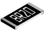
| 描述 | RES 100K OHM 1/16W 0402 0.1% SMD |
| 产品分类 | |
| 品牌 | TT Electronics/Welwyn |
| 数据手册 | |
| 产品图片 |
|
| 产品型号 | PCF0402R-100KBT1 |
| rohs | 无铅 / 符合限制有害物质指令(RoHS)规范要求 |
| 产品系列 | PCF - 精密型 |
| 供应商器件封装 | 0402 |
| 其它名称 | 985-1256-1 |
| 功率(W) | 0.063W,1/16W |
| 包装 | 剪切带 (CT) |
| 大小/尺寸 | 0.039" 长 x 0.020" 宽(1.00mm x 0.50mm) |
| 容差 | ±0.1% |
| 封装/外壳 | 0402(1005 公制) |
| 成分 | 金属薄膜 |
| 标准包装 | 1 |
| 温度系数 | ±25ppm/°C |
| 特性 | - |
| 电阻(Ω) | 100k |
| 端子数 | 2 |
| 高度 | 0.016"(0.40mm) |




- 商务部:美国ITC正式对集成电路等产品启动337调查
- 曝三星4nm工艺存在良率问题 高通将骁龙8 Gen1或转产台积电
- 太阳诱电将投资9.5亿元在常州建新厂生产MLCC 预计2023年完工
- 英特尔发布欧洲新工厂建设计划 深化IDM 2.0 战略
- 台积电先进制程称霸业界 有大客户加持明年业绩稳了
- 达到5530亿美元!SIA预计今年全球半导体销售额将创下新高
- 英特尔拟将自动驾驶子公司Mobileye上市 估值或超500亿美元
- 三星加码芯片和SET,合并消费电子和移动部门,撤换高东真等 CEO
- 三星电子宣布重大人事变动 还合并消费电子和移动部门
- 海关总署:前11个月进口集成电路产品价值2.52万亿元 增长14.8%


PDF Datasheet 数据手册内容提取
Resistors Precision Thin Film Nichrome Chip Resistors PCF Series Precision thin film technology Extended ohmic range 1R - 3M Precision to ±0.01% and 2ppm/°C Passivated range for superior humidity performance Load life stability and humidity to 0.05% Pb-free standard with SnPb option AEC-Q200 grade available AAllll PPbb--ffrreeee ppaarrttss ccoommppllyy wwiitthh EEUU DDiirreecctitivvee 22001111//6655//EEUU aammeennddeedd bbyy ((EEUU)) 22001155//886633 ((RRooHHSS33)) Electrical Data - Standard Range Limiting Element Ohmic Value Range1 Type TCR (ppm/°C) Power (W) Voltage (V) 1% & 0.5% 0.25% 0.1% 0.05% 0.01% 50 49R9-33K PCF0201 0.031 15 - 25 49R9-5K 50 10R-205K - 25 15 49R9-70K 49R9-12K PCF0402 10 0.063 25 49R9-12K 5 - 49R9-5K 49R9-3K 3 49R9 - 4K99 2 50 2R-1M 4R7-1M 25 4R7-332K 15 - 4R7-332K PCF0603 10 0.063 50 5 - 24R9-15K 24R9-100K 3 24R9 – 15K 2 50 1R-2M 4R7-2M 24R9-200K - 25 15 - 4R7-511K 24R9-200K PCF0805 10 0.1 100 24R9-200K 5 - 3 24R9-30K 2 50 1R-2M5 4R7-2M5 - 25 4R7-1M 15 4R7–1M 24R9-500K PCF1206 10 0.125 150 5 - 3 24R9-49K9 2 50 1R-2M5 4R7-2M5 25 15 4R7–1M PCF1210 10 0.2 150 - 5 - 3 24R9-50K 2 50 1R-3M 4R7-3M - 25 4R7-1M 15 4R7-1M 24R9-500K PCF2010 10 0.25 150 5 - 3 24R9-100K 2 50 1R – 3M 4R7-3M - 25 4R7-1M 15 4R7-1M 24R9-500K PCF2512 10 0.5 150 5 - 3 24R9-100K 2 Note 1: Standard values E24 or E96. Other values may be available by request. General Note BI Technologies IRC Welwyn TT Electronics reserves the right to make changes in product specification without notice or liability. All information is subject to TT Electronics’ own data and is considered accurate at time of going to print. www.ttelectronics.com/resistors © TT Electronics plc 06.18
Precision Thin Film Nichrome Chip Resistors PCF Series Electrical Data - AEQ-Q200 Grade - Standard Range TCR Power Limiting Ohmic Value Range * Type Element (ppm/ºC) (W) Voltage (V) 1% 0.5% 0.25% 0.1% 0.05% 50 PCF0402…A 0.063 25 49R9 – 100K 49R9 – 10K 25 50 PCF0603…A 0.063 50 10R – 332K 10R – 49K9 25 50 PCF0805…A 0.1 100 10R – 100K 25 50 PCF1206…A 0.125 150 10R – 200K 25 50 PCF1210…A 0.25 150 10R – 1M0 25 50 PCF2010…A 0.25 150 10R – 499K 25 50 PCF2512…A 0.5 150 25 * Standard values E24 or E96. Electrical Data – High Power Range Limiting Element Ohmic Value Range * Type TCR (ppm/°C) Power (W) Voltage (V) 0.5% 0.25% 0.1% 0.05% 0.01% 50 4R7-1M 25 4R7-332K 24R9-100K 15 4R7-332K PCF0603H 10 0.1 75 5 24R9-15K 3 - 24R9-15K 2 50 1R-1M 4R7-1M 25 4R7-511K 24R9-200K 15 4R7-332K PCF0805H 10 0.125 150 4R7-511K 5 24R9-30K 3 - 24R9-30K 2 50 25 4R7-1M 24R9-500K 15 PCF1206H 10 0.25 200 5 24R9-50K 3 - 24R9-49K9 2 50 25 4R7-1M 24R9-500K 15 PCF1210H 10 0.33 200 5 24R9-50K 3 - 24R9-49K9 2 50 25 4R7-1M 24R9-500K 15 PCF2010H 10 0.33 200 5 24R9-50K 3 - 24R9-49K9 2 50 25 PCF2512H 0.75 200 1R-2K 4R7-2K 24R9-2K 15 10 * Standard values E24 or E96. Other values may be available by request. General Note BI Technologies IRC Welwyn TT Electronics reserves the right to make changes in product specification without notice or liability. All information is subject to TT Electronics’ own data and is considered accurate at time of going to print. www.ttelectronics.com/resistors © TT Electronics plc 06.18
Precision Surface Mount Resistors PCF Series Electrical Data - High Power Range Electrical Data - High Power Range Ohmic Value Range TCR Power Limiting Element Type (pTpCmR/ºC) Pow(We)r VLoimltiatgineg ( V) 0.5% 0.25%Ohmic Va0lu.1e% Range * 0.05% 0.01% Type (W) Element (ppm5/0ºC) 0.5% 0.25% 0.1% 0.05% 0.01% Voltage (V) 25 PCF0603H 5015 0.1 75 4R7-1M4R7-332K 24R9-100K 2510 4R7-332K 24R9-100K PCF0603H 155 0.1 75 4R7-332K 24R9-15K 1050 525 4R7-1M 24R9-15K 4R7-511K 24R9-200K PCF0805H 5015 0.125 150 2510 1R-1M 4R7-5114RK7–1M PCF0805H 155 0.125 150 4R7-1M 24R9-30K 4R7-511K 24R9-200K 50 10 4R7-511K 25 5 4R7-12M4R9-30K 24R9-500K PCF1206H 15 0.25 200 50 10 25 5 4R7-1M24R9-50K 24R9-500K PCF1206H 15 0.25 200 1050 PrePcCFi1s2i1o0nH Thin5 5021F55ilm 0.33 200 4R7-12M4R9-50K 24R9-500K 2510 4R7-1M 24R9-500K NiPcChF1r2o10mHe Chip15 5Resistor0s.33 200 24R9-50K 10 5 24R9-50K PECFl eSecrietrsical 5D0 ata - Passivated Range 25 4R7-1M 24R9-500K PCF2010H 15 0.33 200 10 Ohmic Value Range * TCR Power Limiting Element Type 5 24R9-50K Electrical (Dpp5m0a/ºtCa) - AE(WQ) -Q2V0olt0ag eG (V)rade0 .5–% High0. 2P5%ower0 .1R%ange0.05% 0.01% PPCCFF20541022HP 21255550 00..70563 20205 1R-2K 25R-25K4R7-2K 24R9-2K 10 *E StlPaenCTdFyac0pr6de0 tv3raPluiecs Ea24(pl o pTrmD C215ER5509/º6Ca. )Otthaer va-lPu 0oe(EW.sw0 m6)ex3aryt bee anvaVioldELaillbmtelaeemig tbeie5ndyn 0(grtVe q)uHesti. g1h% Powe0.5r% ROahmnic gV0a24.2l59eu5RRe%-9 3R-31a22nKKge * 0.1% 0.05% 15 25R-100K 5500 PCF0603H…A 0.1 75 10R – 332K10R-800K 10R – 49K9 PCF0805P 2255 0.1 100 15 Limiting Ohmic 2V5aRlu-2e0 R0aKnge * PCPF0CT8Fy01p52eH06…PA (ppTm25C2550R/50º C) P0o0(.Ww.112)2e55r EV1loe5lm01ta5eg0net 0.5% 0.25% 100.1R%-1M 0.05% 100R. 0– 11%00K 5105 (V) 25R-500K PCF1206H…A 0.25 200 10R – 200K PPCCFF02600130XP 522525055050 0.01.6265 110500 10R1 0–R 1-3M302K10R-1M PCPFC1F201800H5…XA 5105 00..2353 201050 10R-500K25R-500K 225550 50 10R-1M 10R – 499K PPCCFF12250162XP 5205 0.303.53 210500 10R-1M PCF2010H…A 25215055 0.33 200 25R-500K PCF2512X 1 200 1R-100R 4R7-100R 25 * Standard values E24 or E96. Other values may be available by request. Physical Data Electrical Data - Passivated Range Dimensions (mm) & Weight (mg) L W Tmax A C Wt 020T1ype 0.6 ± 0.0T5CR 0.3 ± 0P.o0w5er 0.2L6imiting E0l.e1m2 e±n 0t. 05 0.12 ± 0.05 O1hmic Value Range * C 0402 1.0 ± (0p.p05m/ºC) 0.5 ± 0.0(W5) 0.40 Voltage0 (.V2) ± 0.1 0.2 0±. 50%.1 3 0.25% 0.1% T 0P6C0F30402P 1.6 ± 0.25205 0.8 ± 00..2063 0.55 25 0.3 ± 0.2 0.3 ± 0.2 6 25R-2A5K 0805 2.0 ± 0.2 1.25 ± 0.2 0.65 0.4 ± 0.2 0.4 ± 0.2 9 15 49R9-12K 1206 3.2 ± 0.250 1.6 ± 0.2 0.65 0.5 ± 0.2 0.5 ± 0.2 20 L A W 1P2C1F00603P 3.2 ± 0.225 2.6 ± 00..2063 0.50 500.45 ± 0.2 0.5 ± 0.2 25 25R-332K 2010 4.9 ± 0.215 2.4 ± 0.2 0.65 0.5 ± 0.2 0.6 ± 0.2 36 Wrap-around terminations 2512 6.3 ± 0.250 3.1 ± 0.2 0.65 0.5 ± 0.2 0.6 ± 0.2 55 (3 faces) PCF0805P 25 0.1 100 10R - 1M 15 50 Construction PCF1206P 25 0.125 150 10R-1M A thin-film material i1s5 selectively deposited on a 96% alumina substrate together with metallic contacts at each end of the resistor. The unadjusted resist5o0rs are heat treated to give the required TCR and stability, then a precise1l0yR c -o 1nMtr5olled laser trim process adjusts PCF2010P 25 0.25 150 the resistance value. Epoxy protection is applied and wrap-around terminations are added and plated with Nickel then Tin. Each 15 25R - 1M resistor is measured i5m0mediately before packing into tape. 10R - 1M5 PCF2512P 25 0.5 150 Terminations 15 25R - 1M *T hStea ncdharipd sv aalurees sEu24p porl iEe9d6 .w Oitthhe r1 v0al0ue%s m Sany bme aavtatiela bpllea btye dre qwuersatp.-around terminations suitable for soldering. General Note BI Technologies IRC Welwyn TT Electronics reserves the right to make changes in product specification without notice or liability. All information is subject to TT Electronics’ own data and is considered accurate at time of going to print. www.ttelectronics.com/resistors © TT Electronics plc 06.18
Precision Surface Mount Resistors Precision Thin Film Nichrome Chip Resistors PCF Series PCF Series Physical Data Dimensions (mm) and Weight (mg) L W T max A C Wt 0201 0.58 0.05 0.29 0.05 0.26 0.15 0.05 0.12 0.05 0.14 C PPrree0c4c02iissiioonn1 .0SS uu0.1rrffaacc0.5ee 0MM.05oouunn0tt.5 5RR eess0ii.ss25t too 0.r1r5ss 0.2 0.15 0.54 0603 1.6 0.2 0.8 0.2 0.65 0.35 0.25 0.3 0.2 1.8 T 0805 2.0 0.2 1.25 0.2 0.65 0.4 0.25 0.3 0.2 4.7 A PPCCFF1 2 SS06eerriieess3.05 0.15 1.55 0.15 0.65 0.35 0.25 0.42 0.2 9.0 L A W 1210 3.10 0.15 2.5 0.25 0.65 0.55 0.25 0.4 0.3 10 2010 4.9 0.2 2.4 0.25 0.65 0.55 0.3 0.6 0.3 24 Wrap-around terminations (3 faces) 2512 6.3 0.2 3.1 0.25 0.65 0.7 0.45 0.6 0.3 38 PCohnsytrsucitcional Data Physical Data A thin-film material is selectively deposited on a 96% alumina substrate together with metallic contacts at each end of the resistor. The unadjusted resistors are heat treated to give the required TCR and stability, then a precisely controlled laser trim process adjusts the resistance value. Epoxy protDDeiicmmteieonnnssii ooisnn ssa (p(mmpmmlie)) adann addn WWdee wiigghrhatt p ((mm-aggr))ound terminations are added and plated with Nickel then Tin. Each resistor is measureLLd immediateWWly before pTTa mcmkaaixnx g into tapAAe. CC WWtt 00220011 00..5588 00..0055 00..2299 00..0055 00..2266 00..1155 00..0055 00..1122 00..0055 00..1144 CC Term04i0n2ations 1.0 0.1 0.5 0.05 0.55 0.25 0.15 0.2 0.15 0.54 0402 1.0 0.1 0.5 0.05 0.55 0.25 0.15 0.2 0.15 0.54 The 00s66t00a33ndard te11r..6m6 i n 00a..22tion is 001..880 0 %00..22 Sn mat0t0e..66 55p lated w00..3r3a55 p - 0a0..r22o55und s00u..33it a 0b0..l22e for sold11e..88ring. SnPb plated option is available foTrT standard rang00e880 0P55CF over22 t..00h e 00r.e.22stricte11d..22 5r5a n 00g..2e2 below00...6655 00..44 00..2255 00..33 00..22 44..77 AA 111222001660 333...001550 000...111555 112..55.555 000...211555 000...666555 000...353555 000...222555 000..44.422 0 00...322 991..000 LL AA WW Pe12r10form3.1a0 n0.1c5 e 2D.5 a0.2t5a - 0S.65t and0.5a5 r0.d25 R0a.4 n 0.g3 e 10 Sn2200P1100b Te44..r99 m 00..22inat22..i44o 0n0..225 5Opt00i..66o55 n R00a..5555n 0g0..33e 00..66 00..33 2244 WWrraapp--aarroouu(3nn ddfa ttceeerrmms)iinnaattiioonnss 2512 6.3 0.2 3.1 0.25 0.65 0.7 0.45 0.6 0.3 38 (3 faces) 2512 6.3 0.2 3.1 0.25 0.65 0.7 0.45 0.6 0.3 38 Test Parameters PowerConditions Maximum change (+0.05R) TCR Limiting Element Ohmic Value Range CCoonnssttrruuTcyctptiieoonn (ppm/°C) (W) Voltage (V) >0.05% toler1a%nc e 0.5%C h i p s0iz.2e5% ≤00.1.0%5% tolerance A thin-film material is selectively deposited on a 96% alumina substrate togeth0e6r0 w3 titoh 2 m51e2tallic c o n0t2a0c1t,s 0a4t0 e2ach end0 o6f0 3th teo r2e5s1is2tor. A thin-film material is selectively deposited on a 96% alumina substrate together with metallic contacts at each end of the resistor. TThhLoeea uudnn liaafeddjjuusstteedd rreessiissttoorrss aarree5 h0heeaatt ttrreeaatteedd ttoo1 0gg0iivv0ee h ttohhueer s rr ereaqqtueudiirr eelodda dTT CC@RR 7 aa0nn°Cdd ssttaabbiilliittyy,, tthh0ee.nn2 5 aa% pprreecciisseellyy ccoonn1tt0rr0Roo. ll–5llee %2dd5 l0laaKsseerr ttrriimm pprroo0cc.e0es5sss% aaddjjuussttss the resistance value. Epoxy protection is applied and wrap-around terminations are added and plated with Nickel then Tin. Each thHeu rmeisPdiCsittFya0n8c0e5 value. Epoxy 2p5rotection is a1p0p0l0ie0 h.d1o uarnsd @ w 4r0a°pC-,a 9ro0 u- n190d50 %teRrmHinations a0re.3 a%dded and pla1t0e0Rd. –3w %1i0th0K Nickel then0 .T0i5n%. Each resistor is measured immediately before packing into tape. reSshisotrot rt eisr mm oevaesruloraedd immed1ia5tely befor6e. 2p5a xc kraintegd iPnotow etra ,p oer. 2 x LEV, for 5 sec 0.5% 100R. –5 %100K 0.05% TeHrigmhi tneamtpioernasture operation 50 1000 hours at 125°C 0.25% 100R.2 –5 5%00K 0.25% Terminations TThhTeeem sspttaPaeCnrnaFddt1uaa2rrre0dd 6 c ttyeecrrlemmiinnaattiioonn iiss2 1150000%% SSnn mmaattttee 0 pp.1l5laa2 tct5eeydcdl e wws r-r5aa5pp --Caa,rr oo1u2u5nn°d1dC5 ss0uuiittaabbllee ffoorr ssoolldd0ee.r1rii%nngg.. SSnnPPbb ppllaatt1ee0dd0R . oo–1p p%2tt0iioo0nKn iiss aavvaaiillaabbll0ee. 0ffoo5r%r ssttaannddaarrdd rraaRnneggsiees t PaPnCCcFFe ootovv eesror lttdhheeer hrreeesastttrriiccttee1dd5 rraannggee bbeellooww.. 270°C, 10 sec 0.2% 100R. –2 %200K 0.05% Solderability 235°C, 2 sec 95% minimum coverage Performance Data - Standard Range PPeerrffoorrmmaannccee D Dataat a- H- igShta Pnodwaerrd R Raangnege TTTeeesssttt P PPaaarrraaammmeeettteeerrrsss CCCooonnndddiitittiioioonnnsss MMMaaaxxxiiimmmuuummm ccchhhaaannngggeee (((+++000...000555RRR))) Load life 1000 hours rated load @ 70°C >>00..0055%% ttoolleerraannccee CChh0iipp.5 ss%iizzee ≤≤00..0055%% ttoolleerraannccee Humidity 1000hrs @ 40°C, 90 - 95%RH 00660033 ttoo 22551122 002200011.,5, 0%0440022 00660033 ttoo 22551122 LLSoohaaoddr tlli iftfeeerm overload 6.2511 00x 00r0a0t hehdoo uuPrross w rraaettre,e ddo rll oo2aa xdd L@@EV 77, 00fo°°CCr 5 sec 00..2255%% 000...555%%% 00..0055%% HHHuuigmmhiid dtieittymyperature operation 11000000 hh1oo0uu0rrss0 @ @h o 44u00r°°sCC a,,t 991005 5-- °99C55%%RRHH 00..33%% 000...335%%% 00..0055%% SSThheoomrrttp teteerrarmmtu rooevv eceryrllcoolaeadd 66..2255 xx rraatte5edd c PyPcoolwewsee -rr 5 ,, 5 oo°rrC 22, x1x 5LLE0EV°V,C, ffoorr 55 sseecc 00..55%% 000...2555%%% 00..0055%% HHRiieggshhis ttteaemnmcppeee trroaat tsuuorreled oeorpp eherreaaatttiioonn 110000002 7hh0oo°uuCrrs,s 1aa0tt 11s2e2c55°°CC 00..2255%% 000..22.255%%% 00..2255%% TTSeeommldppeeerrraaabttuiulirrteey ccyyccllee 55 ccyyccl2lee3ss 5 --°55C55, CC2,, s11e22c55°°CC 00..11%% 95% min00im..11u%%m coverage 00..0055%% Resistance to solder heat 270°C, 10 sec 0.2% 0.2% 0.05% Resistance to solder heat 270°C, 10 sec 0.2% 0.2% 0.05% PSolederrafboilityrmance Data - Pas2s35°iCv, 2a setced Range 95% minimum coverage Solderability 235°C, 2 sec 95% minimum coverage Performance Data - High Power Range Performance Data - High Power Range Test Parameters Conditions Maximum change (+0.05R) 0603 to 2512 0402 Test Parameters Conditions Maximum change (+0.05R) Test Parameters Conditions Maximum change (+0.05R) Load life 1000 hours rated load @ 70°C 0.05% 0.25% Load life 1000 hours rated load @ 70°C 0.5% LHoaudm liidfeity 11000000 hhorsu r@s r4a0te°Cd ,l o9a0d - @95 7%0°RCH 0.05% 0.5% 0.5% Humidity 1000hrs @ 40°C, 90 - 95%RH 0.5% HSuhmoridt itteyrm overload 6.251 0x 0r0atherds @Po 4w0e°rC, o, r9 20 x- 9LE5V%, fRoHr 5 sec 0.02% 0.5% 0.1% SSHhhioogrrhtt ttteeermrmmp oeorvvaeetrrullooreaa ddoperation 66..2255 xx rraattee1dd0 0PPo0ow wheoerru,, roosr r a 22t x1x 2LL5EEV°VC,, ffoorr 55 sseecc 0.05% 00..55%% 0.5% HHTieiggmhh p tteeemrmaptpueerrreaa ttcuuyrrceele ooppeerraattiioonn 11500 c00y00c lhheoso uu-5rrss5 a aCtt ,11 1552555°°C°CC 0.02% 00..55%% 0.1% TTReememspipseetarraanttcuuerr eet o cc yyscocllleeder heat 55 ccyycc2llee7ss0 --°55C55,° °1CC0,, 1s1e55c00°°CC 0.02% 00..2255%% 0.1% RRSeeossliidsstteaarnnacbceeil itttoyo ssoollddeerr hheeaatt 22727030°5°CC°C,, 1,1 020 ssseeeccc 95% min00i.m.22%u%m coverage SSoollddeerraabbiilliittyy 223355°°CC,, 22 sseecc 9955%% mmiinniimmuumm ccoovveerraaggee Performance Data - Passivated Range Performance Data - Passivated Range General Note BI Technologies IRC Welwyn © Welwyn Components Limited Bedlington Northumberland NE22 7AA, UK TTTe lEelpechtoronneic: sTT+ ree4ess4set tr(v 0 ePP)s a a1th6rrea7a r0mimg 8het2e t2ttoe1e m8rr1assk eF cahcasnimgeilse i:n + p4ro4d (u0c)t 1sp6e7c0ifi c8a2ti9oC4Cn 6owo5intn h Edodmuiittta niiioloo: tniinncesfs oo@r liwabeillwityy.n-tt.com Website: wwwMM.waaelxxwiiymmn-utut.mmco m cchhaannggee ((++00..0055RR)) 03.11 All information is subject to TT Electronics’ own data and is considered accurate at time of going to print. 0603 to 2512 www.tt0el4ec0t2ronics.com/resistors 0603 to 2512 0402 ©LLoo TaaTdd Elliilffeeectronics plc 11000000 hhoouurrss rraatteedd llooaadd @@ 7700°°CC 00..0055%% 00..2255%% HHuummiiddiittyy 11000000hhrrss @@ 4400°°CC,, 9900 -- 9955%%RRHH 00..0055%% 00..55%% 06.18 SShhoorrtt tteerrmm oovveerrllooaadd 66..2255 xx rraatteedd PPoowweerr,, oorr 22 xx LLEEVV,, ffoorr 55 sseecc 00..0022%% 00..11%% HHiigghh tteemmppeerraattuurree ooppeerraattiioonn 11000000 hhoouurrss aatt 112255°°CC 00..0055%% 00..55%% TTeemmppeerraattuurree ccyyccllee 55 ccyycclleess --5555 CC,, 112255°°CC 00..0022%% 00..11%% RReessiissttaannccee ttoo ssoollddeerr hheeaatt 227700°°CC,, 1100 sseecc 00..0022%% 00..11%% SSoollddeerraabbiilliittyy 223355°°CC,, 22 sseecc 9955%% mmiinniimmuumm ccoovveerraaggee ©© WWeellwwyynn CCoommppoonneennttss LLiimmiitteedd BBeeddlliinnggttoonn NNoorrtthhuummbbeerrllaanndd NNEE2222 77AAAA,, UUKK TTeelleepphhoonnee:: ++4444 ((00)) 11667700 882222118811 FFaaccssiimmiillee:: ++4444 ((00)) 11667700 882299446655 EEmmaaiill:: iinnffoo@@wweellwwyynn--tttt..ccoomm WWeebbssiittee:: wwwwww..wweellwwyynn--tttt..ccoomm 0033..1111
Precision Surface Mount Resistors PCF Series Physical Data Dimensions (mm) and Weight (mg) L W T max A C Wt 0201 0.58 0.05 0.29 0.05 0.26 0.15 0.05 0.12 0.05 0.14 C 0402 1.0 0.1 0.5 0.05 0.55 0.25 0.15 0.2 0.15 0.54 0603 1.6 0.2 0.8 0.2 0.65 0.35 0.25 0.3 0.2 1.8 T 0805 2.0 0.2 1.25 0.2 0.65 0.4 0.25 0.3 0.2 4.7 A 1206 3.05 0.15 1.55 0.15 0.65 0.35 0.25 0.42 0.2 9.0 L A W 1210 3.10 0.15 2.5 0.25 0.65 0.55 0.25 0.4 0.3 10 2010 4.9 0.2 2.4 0.25 0.65 0.55 0.3 0.6 0.3 24 Wrap-around terminations (3 faces) 2512 6.3 0.2 3.1 0.25 0.65 0.7 0.45 0.6 0.3 38 Construction A thin-film material is selectively deposited on a 96% alumina substrate together with metallic contacts at each end of the resistor. The unadjusted resistors are heat treated to give the required TCR and stability, then a precisely controlled laser trim process adjusts the resistance value. Epoxy protection is applied and wrap-around terminations are added and plated with Nickel then Tin. Each resistor is measured immediately before packing into tape. Terminations The standard termination is 100% Sn matte plated wrap-around suitable for soldering. SnPb plated option is available for standard range PCF over the restricted range below. Performance Data - Standard Range Test Parameters Conditions Maximum change (+0.05R) >0.05% tolerance Chip size ≤0.05% tolerance 0603 to 2512 0201, 0402 0603 to 2512 Load life 1000 hours rated load @ 70°C 0.25% 0.5% 0.05% Humidity 1000 hours @ 40°C, 90 - 95%RH 0.3% 0.3% 0.05% Short term overload 6.25 x rated Power , or 2 x LEV, for 5 sec 0.5% 0.5% 0.05% High temperature operation 1000 hours at 125°C 0.25% 0.25% 0.25% Temperature cycle 5 cycles -55 C, 125°C 0.1% 0.1% 0.05% Resistance to solder heat 270°C, 10 sec 0.2% 0.2% 0.05% Solderability 235°C, 2 sec 95% minimum coverage Performance Data - High Power Range Test Parameters Conditions Maximum change (+0.05R) PLroeadc liifseion Thin Film 1000 hours rated load @ 70°C 0.5% Humidity 1000hrs @ 40°C, 90 - 95%RH 0.5% NShicorht treormm oveer lCoahdip Resistors 6.25 x rated Power, or 2 x LEV, for 5 sec 0.5% High temperature operation 1000 hours at 155°C 0.5% PTCemF pSeerartiuerse cycle 5 cycles -55°C, 150°C 0.25% Resistance to solder heat 270°C, 10 sec 0.2% Solderability 235°C, 2 sec 95% minimum coverage Performance Data - Passivated Range Test Parameters Conditions Maximum change (+0.05R) 0603 to 2512 0402 Load life 1000 hours rated load @ 70°C 0.05% 0.25% Humidity 1000hrs @ 40°C, 90 - 95%RH 0.05% 0.5% Short term overload 6.25 x rated Power, or 2 x LEV, for 5 sec 0.02% 0.1% High temperature operation 1000 hours at 125°C 0.05% 0.5% Temperature cycle 5 cycles -55 C, 125°C 0.02% 0.1% Resistance to solder heat 270°C, 10 sec 0.02% 0.1% Solderability 235°C, 2 sec 95% minimum coverage 0 100% 100% 70 100% 100% Derating Curve 125 35% 0% Precision Surface Mount Resi1s55tors0% © Welwyn Components Limited Bedlington Northumberland NE22 7AA, UK Telephone: +44 (0) 1670 822181 Facsimile: +44 (0) 1670 829465 Email: info@welwyn-tt.com Website: www.welwyn-tt.com 03.11 Temperature Derating PCF Series 100% Pr on of 6800%% PStaasnsidvaartde d& RHaignhg eP ower Derating Curve orti 40% p Pro 20% 0% 0 50 100 150 Ambient Temperature (°C) Solderability The terminations have an electroplated nickel barrier and tin coating. This ensures excellent 'leach' resistance properties and solderability. Packaging PCF Resistors are supplied taped and reeled as as per IEC 286-3. Sizes 2010 and 2512 are in embossed plastic tape. Smaller sizes are in paper tape. Application Notes PCF resistors are ideally suited for handling by automatic methods due to their rectangular shape and the small dimensional tolerances. Electrical connection to a ceramic substrate or to a printed circuit board can be made by reflow or wave soldering of wrap-around terminations. Wrap-around terminations provide good leach properties and ensure reliable contact. Due to the robust construction, the PCF can be immersed in the solder bath for 30 seconds at 260°C. This enables the resistor to be mounted on one side of a printed circuit board and wire-leaded components applied on the other side. PCF resistors themselves can operate at a maximum temperature of 125°C (see performance above) (155°C for High Power grades). For soldered resistors, the joint temperature should not exceed 110°C. This condition is met when the stated power levels at 70°C are used. General Note BI Technologies IRC Welwyn TT Electronics reserves the right to make changes in product specification without notice or liability. All information is subject to TT Electronics’ own data and is considered accurate at time of going to print. www.ttelectronics.com/resistors © TT Electronics plc 06.18 © Welwyn Components Limited Bedlington Northumberland NE22 7AA, UK Telephone: +44 (0) 1670 822181 Facsimile: +44 (0) 1670 829465 Email: info@welwyn-tt.com Website: www.welwyn-tt.com 03.11
Precision Thin Film Nichrome Chip Resistors PCF Series Ordering Procedure This product has two valid part numbers: European (Welwyn)Part Number**:PCF0603-11-1K54BI(0603,standard,15ppm/°C, 1.54kilohm±0.1%,Pb-free) P C F 0 6 0 3 - 1 1 - 1 K 5 4 B I 1 2 3 4 5 6 7 1 2 3 4 5 6 7 Type Size Range TCR Value Tolerance Termination & Packing PCF 0201 Omit for -20 = ±2ppm/°C E24 = 3/4characters L = ±0.01% A = AEC-Q200 grade, Pb-free 0402 Standard -19 = ±3ppm/°C E96 = 3/4 characters W = ±0.05% I = Standard grade, Pb-free 0603 H = High Power -13 = ±5ppm/°C R = ohms B = ±0.1% Standard Packing 0805 P = Passivated -12 = ±10ppm/°C K = kilohms C = ±0.25% 0201, 0402 10,000/reel 1206 -11 = ±15ppm/°C M = megohms D = ±0.5% 0603to 1210 5000/reel 1210 R = ±25ppm/°C F = ±1% 2010, 2512 4000/reel 2010 -02 = ±50ppm/°C T1* = Pb-free, 1K reel 2512 0201 to 1206, 1000/reel 2010, 2512 PB = SnPb, 1K reel 0805, 1206 1000/reel * Non-standard; enquire to confirm availability ** Applies to all Ranges, Termination and Packing options. USA (IRC)Part Number*:PCF-W0603LF-11-1541-B-P-LT(0603, standard, 15ppm/°C, 1.54 kilohm ±0.1%,Pb-free) P C F - W 0 6 0 3 L F - 1 1 - 1 5 4 1 - B - P - L T 1 2 3 4 5 6 7 8 1 2 3 4 5 6 7 8 Type Model Termination TCR Value Tolerance Tape Packing PCF W0201 LF = Pb-free 13 = ±5ppm/°C 3 digits + multiplier T = ±0.01% P = Paper LT = Tape & Reel W0402 (100%Sn) 12 = ±10ppm/°C R = ohms for A = ±0.05% (0201 to 1210) 0201, 0402 10,000/reel W0603 11 = ±15ppm/°C values <100 ohms B = ±0.1% E = Embossed 0603 to 1210 5000/reel W0805 03 = ±25ppm/°C C = ±0.25% (2010, 2512) 2010, 2512 4000/reel W1206 02 = ±50ppm/°C D = ±0.5% W1210 F = ±1% W2010 W2512 * Applies only to Standard Range, Pb-Fr ee parts General Note BI Technologies IRC Welwyn TT Electronics reserves the right to make changes in product specification without notice or liability. All information is subject to TT Electronics’ own data and is considered accurate at time of going to print. www.ttelectronics.com/resistors © TT Electronics plc 06.18
Mouser Electronics Authorized Distributor Click to View Pricing, Inventory, Delivery & Lifecycle Information: T T Electronics: PCF2010R-15KBI PCF2010R-162RBI PCF2512R-1M13BI PCF2010R-12K1BI PCF1206R-93R1BI PCF1206R- 976KBI PCF1206R-20KBI PCF1206R-243KBI PCF0805R-56K2BI PCF1206R-78R7BI PCF1206R-19K1BI PCF1206R-1K3BI PCF0805R-6K2BI PCF1206R-9R76BI PCF2010R-115KBI PCF0805R-2K55BI PCF0805R-56RBI PCF0805R-576KBI PCF2010R-5K76BI PCF1206R-681RBI PCF1206R-715RBI PCF2010R-5R62BI PCF2010R- 634KBI PCF2010R-6K98BI PCF2010R-768KBI PCF2010R-76K8BI PCF2010R-845RBI PCF0805R-487KBI PCF0805R-5R1BI PCF0805R-5R9BI PCF0805R-8R06BI PCF0805R-90R9BI PCF0805R-910KBI PCF1206R-1K58BI PCF1206R-80R6BI PCF1206R-845KBI PCF1206R-84K5BI PCF0805R-22R1BI PCF1206R-910KBI PCF0805R- 62RBI PCF1206R-8R66BI PCF1206R-90R9BI PCF1206R-91RBI PCF1206R-1M96BI PCF0805R-2K1BI PCF2010R-12K7BI PCF2010R-12RBI PCF0805R-866RBI PCF0805R-2K4BI PCF0805R-2K67BI PCF0805R-620RBI PCF2010R-7K68BI PCF0805R-57K6BI PCF0805R-57R6BI PCF0805R-5R76BI PCF0805R-732KBI PCF2010R- 10R2BI PCF0805R-5K11BI PCF0805R-5K36BI PCF0805R-5K6BI PCF1206R-665RBI PCF1206R-68KBI PCF1206R-71R5BI PCF0603R-68KBI PCF0603R-80K6BI PCF0805R-105KBI PCF2010R-118KBI PCF2010R- 169KBI PCF0805R-56KBI PCF0603R-107KBI PCF0805R-18K2BI PCF0805R-30K1BI PCF0603R-28KBI PCF0603R-3K09BT1 PCF0603R-57K6BT1 PCF2010R-16RBI PCF0805R-54K9BI PCF0805R-5K62BI PCF0805R- 604KBI PCF1206R-887KBI PCF2010R-107RBI PCF1206R-1K65BI PCF1206R-267RBI PCF1206R-9R31BI PCF1206R-931KBI PCF1206R-9R09BI PCF2010R-16R9BI PCF1206R-14KBI PCF1206R-18K2BI PCF1206R-7R5BI PCF1206R-7R87BI PCF0805R-26R1BI PCF1206R-1K15BI PCF0805R-80R6BI PCF0805R-82RBI PCF2010R- 68K1BI PCF2010R-6K19BI PCF0805R-8R25BI PCF0805R-9R09BI PCF1206R-267KBI
 Datasheet下载

