ICGOO在线商城 > PATT0603E10R0BGT1

 Datasheet下载
- 型号: PATT0603E10R0BGT1
- 制造商: Vishay
- 库位|库存: xxxx|xxxx
- 要求:
| 数量阶梯 | 香港交货 | 国内含税 |
| +xxxx | $xxxx | ¥xxxx |
查看当月历史价格
查看今年历史价格
PATT0603E10R0BGT1产品简介:
ICGOO电子元器件商城为您提供PATT0603E10R0BGT1由Vishay设计生产,在icgoo商城现货销售,并且可以通过原厂、代理商等渠道进行代购。 提供PATT0603E10R0BGT1价格参考以及VishayPATT0603E10R0BGT1封装/规格参数等产品信息。 你可以下载PATT0603E10R0BGT1参考资料、Datasheet数据手册功能说明书, 资料中有PATT0603E10R0BGT1详细功能的应用电路图电压和使用方法及教程。
| 参数 | 数值 |
| 产品目录 | |
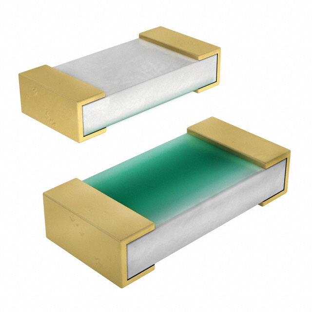
| 描述 | RES 10 OHM 0.15W 0.1% 0603 |
| 产品分类 | |
| 品牌 | Vishay Thin Film |
| 数据手册 | |
| 产品图片 |
|
| 产品型号 | PATT0603E10R0BGT1 |
| rohs | 无铅 / 符合限制有害物质指令(RoHS)规范要求 |
| 产品系列 | PATT |
| 产品培训模块 | http://www.digikey.cn/PTM/IndividualPTM.page?site=cn&lang=zhs&ptm=30302 |
| 供应商器件封装 | 0603 |
| 其它名称 | 764-1040-6 |
| 功率(W) | 0.15W |
| 包装 | Digi-Reel® |
| 大小/尺寸 | 0.064" 长 x 0.032" 宽(1.63mm x 0.81mm) |
| 容差 | ±0.1% |
| 封装/外壳 | 0603(1608 公制) |
| 成分 | |
| 标准包装 | 1 |
| 温度系数 | ±25ppm/°C |
| 特性 | 耐硫,获得 AEC-Q200 汽车认证、 防潮 |
| 特色产品 | http://www.digikey.cn/product-highlights/zh/patt-automotive-thinfilm-chip-resistor/52802 |
| 电阻(Ω) | 10 |
| 端子数 | 2 |
| 高度 | 0.018"(0.46mm) |


- 商务部:美国ITC正式对集成电路等产品启动337调查
- 曝三星4nm工艺存在良率问题 高通将骁龙8 Gen1或转产台积电
- 太阳诱电将投资9.5亿元在常州建新厂生产MLCC 预计2023年完工
- 英特尔发布欧洲新工厂建设计划 深化IDM 2.0 战略
- 台积电先进制程称霸业界 有大客户加持明年业绩稳了
- 达到5530亿美元!SIA预计今年全球半导体销售额将创下新高
- 英特尔拟将自动驾驶子公司Mobileye上市 估值或超500亿美元
- 三星加码芯片和SET,合并消费电子和移动部门,撤换高东真等 CEO
- 三星电子宣布重大人事变动 还合并消费电子和移动部门
- 海关总署:前11个月进口集成电路产品价值2.52万亿元 增长14.8%


PDF Datasheet 数据手册内容提取
PATT www.vishay.com Vishay Dale Thin Film Precision Automotive High Temperature (155 °C at Full Rated Power) Thin Film Chip Resistor, AEC-Q200 Qualified FEATURES • Resistance range: 1.0 to 1 M • AEC-Q200 qualified, table 7F • AEC-Q200 qualified, ESD rated class 1C (< 1 k: 1 kV; > 1 k: 2 kV) • Laser trimmed to any value • Intrinsic moisture protected resistor element • Moisture resistant to MIL-STD-202, method 106 • Tantalum nitride resistor film on alumina substrate • 100 % visual inspected per MIL-PRF-55342 The terminations consist of an adhesion layer, a leach • Laser-trimmed tolerances to ± 0.1 % resistant nickel barrier and gold plating compatible with high • Load life stability 0.2 % at 1000 h at 155 °C and 100 % temperature solder systems. rated power • Very low noise and voltage coefficient CONSTRUCTION (< -30 dB, < 0.1 ppm/V) Ta ntalum Nitride Passivation Resistive Film • Sulfur resistant (per ASTM B809-95 humid vapor test) Gold • Material categorization: for definitions of complianc e please see www.vishay.com/doc?99912 Nickel Barrier TYPICAL PERFORMANCE High Purity Alumina Substrate Adhesion Layer ABSOLUTE TCR 25 TOL. 0.1 STANDARD ELECTRICAL SPECIFICATIONS TEST SPECIFICATIONS CONDITIONS Material Tantalum nitride - Resistance Range 1.0 to 1 M - TCR: Absolute ± 25 ppm/°C to ± 100 ppm/°C -55 °C to +175 °C Tolerance: Absolute ± 0.1 % to ± 1.0 % +25 °C 1000 h at 155 °C Stability: Absolute ± 0.2 % and 100 % rated power Stability: Ratio Not applicable - Voltage Coefficient Less than 0.1 ppm/V - Working Voltage 75 V - Operating Temperature Range -55 °C to +250 °C - Storage Temperature Range (1) -55 °C to +250 °C - Noise < -30 dB - Shelf Life Stability: Absolute 100 ppm 1 year at 25 °C Note (1) Storage temperature rating is for device only COMPONENT RATINGS CASE SIZE POWER RATING (mW) WORKING VOLTAGE (V) RESISTANCE RANGE () 0402 50 75 1.5 to 51K 0603 150 75 2.75 to 120K 0805 200 100 2.75 to 301K 1206 400 200 1.0 to 1M Revision: 14-Mar-2019 1 Document Number: 60124 For technical questions, contact: thinfilm@vishay.com THIS DOCUMENT IS SUBJECT TO CHANGE WITHOUT NOTICE. THE PRODUCTS DESCRIBED HEREIN AND THIS DOCUMENT ARE SUBJECT TO SPECIFIC DISCLAIMERS, SET FORTH AT www.vishay.com/doc?91000
PATT www.vishay.com Vishay Dale Thin Film DIMENSIONS in inches D T D W T E L L CASE SIZE L W T D E 0402 0.042 ± 0.008 0.022 ± 0.005 0.015 ± 0.003 0.010 ± 0.005 0.010 ± 0.005 0603 0.064 ± 0.006 0.032 ± 0.005 0.015 ± 0.003 0.012 ± 0.005 0.015 ± 0.005 0805 0.080 ± 0.006 0.050 ± 0.005 0.015 ± 0.003 0.016 ± 0.008 0.015 ± 0.005 1206 0.126 ± 0.008 0.063 ± 0.005 0.015 ± 0.003 0.020 + 0.005 / - 0.01 0.020 + 0.005 / -0.01 ENVIRONMENTAL TESTS TYPICAL VISHAY ENVIRONMENTAL TEST CONDITIONS PERFORMANCE High temperature storage MIL-STD-202 method 108, 1000 h at 125 °C ± 0.05 % JESD22 method JA-104, 1000 cycles, Temperature cycling ± 0.115 % -55 °C to +155 °C Moisture resistance MIL-STD-202 method 106 ± 0.017 % MIL-STD-202 method 103, 1000 h at 85 °C, 85 % RH, Biased humidity ± 0.133 % 10 % rated power ± 0.20 % at 100 % MIL-STD-202 method 108, Life rated power and 155 °C. 1000 h at 155 °C Effective film temperature is 200 °C. Mechanical shock MIL-STD-202 method 213, condition C ± 0.008 % Vibration MIL-STD-202 method 204, 10 Hz to 2 kHz ± 0.008 % Resistance to soldering heat MIL-STD-202 method 210, condition B ± 0.09 % AEC-Q200-002, human body Electrostatic discharge ± 0.10 % at 2 kV (< 1 k: 1 kV; > 1 k: 2 kV) Solderability MIL-STD-883 method 2003 para 2.3.1 and J-STD-002 Pass Die shear MIL-PRF-55342 Pass Flame retardance AEC-Q200-001 para 4.0 Pass MECHANICAL SPECIFICATIONS Resistive element Tantalum nitride Substrate material Alumina Terminations Gold (10 μin. min.) over nickel (50 μin. min.) DERATING CURVE 100 wer 80 o P ed 60 at R of 40 nt e c er 20 P 0 - 55 0 50 100 155 200 250 Ambient Temperature °C Revision: 14-Mar-2019 2 Document Number: 60124 For technical questions, contact: thinfilm@vishay.com THIS DOCUMENT IS SUBJECT TO CHANGE WITHOUT NOTICE. THE PRODUCTS DESCRIBED HEREIN AND THIS DOCUMENT ARE SUBJECT TO SPECIFIC DISCLAIMERS, SET FORTH AT www.vishay.com/doc?91000
PATT www.vishay.com Vishay Dale Thin Film GLOBAL PART NUMBER INFORMATION New Global Part Numbering: PATT0603E1002BGT1 P A T T 0 6 0 3 E 1 0 0 2 B G T 1 GLOBAL CASE TCR RESISTANCE TOLERANCE TERMINATION PACKAGING MODEL SIZE CHARACTERISTIC PATT 0402 E = ± 25 ppm/°C The first 3 digits are B = ± 0.1 % G =wraparound BULK 0603 H = ± 50 ppm/°C significant figures and D = ± 0.5 % gold over nickel BS = 100 min., 1 mult. 0805 K = ± 100 ppm/°C (1) the last digit specifies F = ± 1.0 % barrier WAFFLE 1206 L = ± 200 ppm/°C the number of zeros G = ± 2.0 % WS = 100 min., 1 mult. to follow. “R” J = ± 5.0 % W0 = 100 min.,100 mult. designates the decimal point. WI = 100 min.,1 mult. (item single lot date code) Example: WP = 100 min.,1 mult. 10R0 = 10 (package unit single lot 1000 = 100 date code) 1002 = 10 k TAPE AND REEL T0 = 100 min., 100 mult. T1 = 1000 min., 1000 mult. T3 = 300 min., 300 mult. T5 = 500 min., 500 mult. TF = full reel TS = 100 min., 1 mult. TI = 100 min., 1 mult. (item single lot date code) TP = 100 min., 1 mult. (package unit single lot date code) Note (1) Characteristic TCR - (R < 10 ) TCR TOLERANCE RESISTANCE (ppm/°C) (%) 10 to 1 M 25, 50, 100, 200 0.1, 0.5, 1, 2, 5 5 to 10 (2) 100, 200 1, 2, 5 1.0 to 5 (2) 200 1, 2, 5 Note (2) Resistance values from 1.0 to 10 are undergoing PPAP qualification; results are expected to be similar to PPAP qualified 10 to 120 k Revision: 14-Mar-2019 3 Document Number: 60124 For technical questions, contact: thinfilm@vishay.com THIS DOCUMENT IS SUBJECT TO CHANGE WITHOUT NOTICE. THE PRODUCTS DESCRIBED HEREIN AND THIS DOCUMENT ARE SUBJECT TO SPECIFIC DISCLAIMERS, SET FORTH AT www.vishay.com/doc?91000
Legal Disclaimer Notice www.vishay.com Vishay Disclaimer ALL PRODUCT, PRODUCT SPECIFICATIONS AND DATA ARE SUBJECT TO CHANGE WITHOUT NOTICE TO IMPROV E RELIABILITY, FUNCTION OR DESIGN OR OTHERWISE. Vishay Intertechnology, Inc., its affiliates, agents, and employees, and all persons acting on its or their behalf (collectively, “Vishay”), disclaim any and all liability for any errors, inaccuracies or incompleteness contained in any datasheet or in any other disclosure relating to any product. Vishay makes no warranty, representation or guarantee regarding the suitability of the products for any particular purpose o r the continuing production of any product. To the maximum extent permitted by applicable law, Vishay disclaims (i) any and all liability arising out of the application or use of any product, (ii) any and all liability, including without limitation special, consequential or incidental damages, and (iii) any and all implied warranties, including warranties of fitness for particular purpose, non-infringement and merchantability. Statements regarding the suitability of products for certain types of applications are based on Vishay’s knowledge of typical requirements that are often placed on Vishay products in generic applications. Such statements are not binding statements about the suitability of products for a particular application. It is the customer’s responsibility to validate that a particular product with the properties described in the product specification is suitable for use in a particular application. Parameters provided in datasheets and / or specifications may vary in different applications and performance may vary over time. All operating parameters, including typical parameters, must be validated for each customer application by the customer’s technical experts. Product specifications do not expand or otherwise modify Vishay’s terms and conditions of purchase, including but not limited to the warranty expressed therein. Except as expressly indicated in writing, Vishay products are not designed for use in medical, life-saving, or life-sustainin g applications or for any other application in which the failure of the Vishay product could result in personal injury or death. Customers using or selling Vishay products not expressly indicated for use in such applications do so at their own risk . Please contact authorized Vishay personnel to obtain written terms and conditions regarding products designed for such applications. No license, express or implied, by estoppel or otherwise, to any intellectual property rights is granted by this documen t or by any conduct of Vishay. Product names and markings noted herein may be trademarks of their respective owners. © 2019 VISHAY INTERTECHNOLOGY, INC. ALL RIGHTS RESERVED Revision: 01-Jan-2019 1 Document Number: 91000