 Datasheet下载
- 型号: P6D-04P
- 制造商: Omron Electronics LLC
- 库位|库存: xxxx|xxxx
- 要求:
| 数量阶梯 | 香港交货 | 国内含税 |
| +xxxx | $xxxx | ¥xxxx |
查看当月历史价格
查看今年历史价格
P6D-04P产品简介:
ICGOO电子元器件商城为您提供P6D-04P由Omron Electronics LLC设计生产,在icgoo商城现货销售,并且可以通过原厂、代理商等渠道进行代购。 P6D-04P价格参考¥13.00-¥13.00。Omron Electronics LLCP6D-04P封装/规格:继电器插座, Relay Socket Through Hole。您可以下载P6D-04P参考资料、Datasheet数据手册功能说明书,资料中有P6D-04P 详细功能的应用电路图电压和使用方法及教程。
Omron Electronics Inc-EMC Div的P6D-04P继电器插座主要应用于工业自动化、电信设备、电力系统和家电控制等领域。这种继电器插座具有高可靠性和稳定性,能够确保电路在各种复杂环境下的正常运行。

 工业自动化
在工业自动化领域,P6D-04P常用于控制机械设备的动作顺序和逻辑控制。例如,在生产线上的输送带控制系统中,继电器插座可以与传感器、控制器等设备配合,实现对电机、气缸等执行机构的精准控制。它还可以用于PLC(可编程逻辑控制器)系统中,作为输入输出接口,帮助处理复杂的逻辑运算和信号传递。

 电信设备
在电信行业中,P6D-04P继电器插座广泛应用于交换机、路由器和其他通信设备中。这些设备需要在不同电压等级之间进行切换或隔离,以确保信号传输的稳定性和安全性。P6D-04P能够承受较高的电流和电压,保证通信设备在长时间工作中的可靠性。

 电力系统
在电力系统中,继电器插座用于配电柜、断路器等设备中,起到保护电路和控制开关的作用。它可以快速响应过载、短路等异常情况,并及时切断电源,防止事故发生。此外,P6D-04P还适用于智能电网中的远程监控和管理,通过与传感器和通信模块结合,实现对电力设备状态的实时监测和控制。

 家电控制
在家用电器方面,P6D-04P继电器插座常见于空调、洗衣机、冰箱等大型家电中。它负责控制压缩机、风扇等关键部件的工作状态,确保家电按照预设程序运行。同时,继电器插座还能提供一定的过载保护功能,延长家电使用寿命。

总之,Omron Electronics Inc-EMC Div的P6D-04P继电器插座凭借其优良的性能和广泛的适用性,在多个行业中发挥着重要作用。
| 参数 | 数值 |
| 产品目录 | |
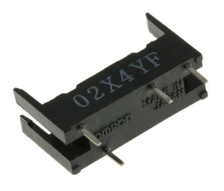
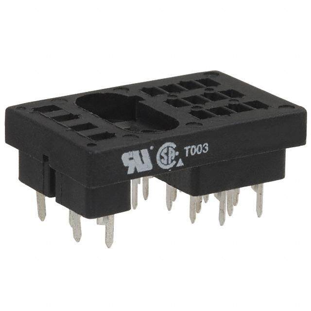
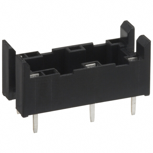
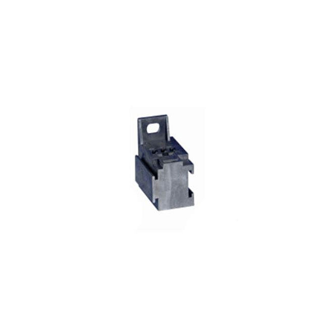
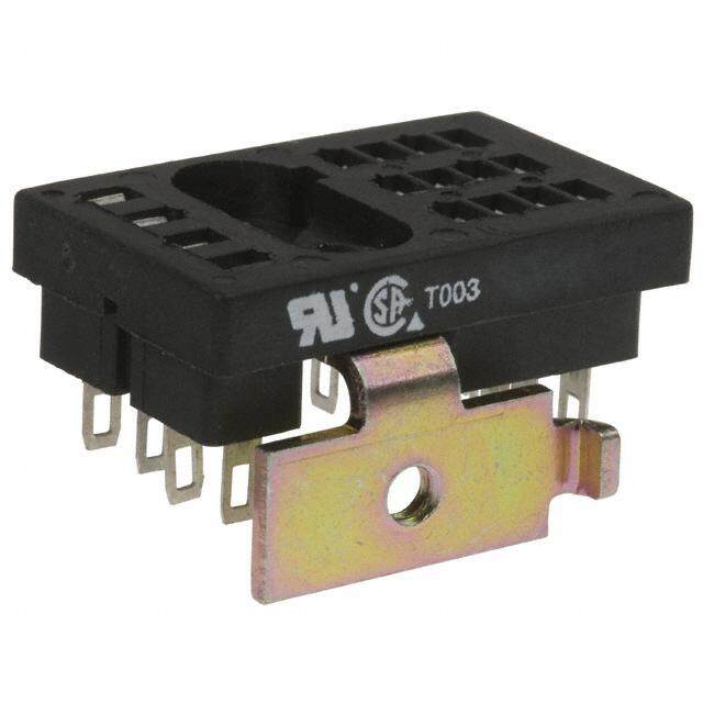
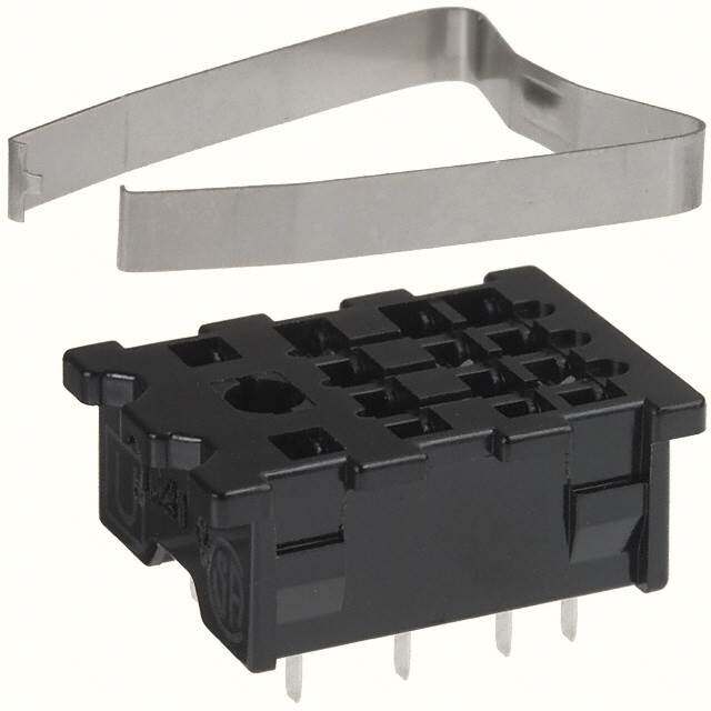
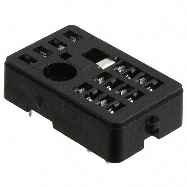
| 描述 | RELAY SOCKET PC MNT FOR G6D-ASI继电器插座与硬件 PC MT SOCKET FOR G6D |
| 产品分类 | |
| 品牌 | Omron Electronics |
| 产品手册 | |
| 产品图片 |
|
| rohs | 符合RoHS无铅 / 符合限制有害物质指令(RoHS)规范要求 |
| 产品系列 | 继电器插座与硬件,Omron Electronics P6D-04PG6D-ASI |
| 数据手册 | |
| 产品型号 | P6D-04P |
| 产品培训模块 | http://www.digikey.cn/PTM/IndividualPTM.page?site=cn&lang=zhs&ptm=25458 |
| 产品目录页面 | |
| 产品种类 | 继电器插座与硬件 |
| 其它名称 | P6D-04P-ND |
| 其它有关文件 | |
| 商标 | Omron Electronics |
| 安装类型 | 通孔 |
| 安装风格 | Socket |
| 工厂包装数量 | 25 |
| 极数 | 1 |
| 标准包装 | 25 |
| 特性 | - |
| 相关继电器系列 | G6D-1A |
| 端子类型 | PC 引脚 |
| 类型 | 插口 |
| 系列 | P6D |
| 配套使用产品/相关产品 | G6D-ASI 系列 |
| 配用 | /product-detail/zh/G6D-1A-ASI%20DC9/G6D-1A-ASIDC9-ND/1815969/product-detail/zh/G6D-1A-ASI%20DC6/G6D-1A-ASIDC6-ND/1815968/product-detail/zh/G6D-1A-ASI%20DC24/Z2244-ND/765537/product-detail/zh/G6D-1A-ASI%20DC5/Z2243-ND/765536/product-detail/zh/G6D-1A-ASI%20DC12/Z2242-ND/765535 |
| 针脚数 | 4 |
| 附件类型 | Sockets |
| 零件号别名 | 380997 9949631 P6D04PNC |


- 商务部:美国ITC正式对集成电路等产品启动337调查
- 曝三星4nm工艺存在良率问题 高通将骁龙8 Gen1或转产台积电
- 太阳诱电将投资9.5亿元在常州建新厂生产MLCC 预计2023年完工
- 英特尔发布欧洲新工厂建设计划 深化IDM 2.0 战略
- 台积电先进制程称霸业界 有大客户加持明年业绩稳了
- 达到5530亿美元!SIA预计今年全球半导体销售额将创下新高
- 英特尔拟将自动驾驶子公司Mobileye上市 估值或超500亿美元
- 三星加码芯片和SET,合并消费电子和移动部门,撤换高东真等 CEO
- 三星电子宣布重大人事变动 还合并消费电子和移动部门
- 海关总署:前11个月进口集成电路产品价值2.52万亿元 增长14.8%


PDF Datasheet 数据手册内容提取
G3DZ Solid State Relays SSR Identical to the G6D in Size with AC/DC dual-use type and DC-only Type Available for the Whole Product Line •10-μA current leakage max. between open output terminals. (cid:129)2,500-VAC dielectric strength ens ured between input and output terminals. (cid:129)With or without input resistor incorporated models available. (cid:129)Incorporated with overvoltage absorption circuit (models with AC/DC output only). (cid:129)Full-wave rectified and half-wave rectified AC current switchable (excluding G3DZ-DZ02P(G)). (cid:129)Standard models are available with UL and CSA certification. RoHS Compliant Refer to "Solid State Relays Common Precautions". ■Model Number Legend G G3DZ-@@@@@@ 3 ————— — — D 1 2 3 4 5 Z 1. Rated Load Power 2. Rated Load Current 3. Terminal Type 5. Input Resistance Supply Voltage R5: 0.5 A P: PCB terminals None: With input 1 : 125 VAC R6: 0.6 A resistance 4. Zero Cross Function (For AC/DC 2 : 240 VAC 02: 2 A G : Without input dual-use type only) DZ: 24 VDC resistance L: Not equipped with zero cross function ■List of Models •With Input Resistance Isolation Zero cross function Indicator Rated output load Rated input voltage Model Minimum packing unit 5 VDC 0.6 A 5 to 240 VAC 12 VDC G3DZ-2R6PL 5 to 100 VDC 24 VDC 5 VDC 0.5 A Photo-voltage No No 5 to 100 VAC 12 VDC G3DZ-1R5PL 25 pcs coupler 5 to 100 VDC 24 VDC 5 VDC 2.0 A 12 VDC G3DZ-DZ02P 5 to 24 VDC 24 VDC (cid:129)Without Input Resistance Isolation Zero cross function Indicator Rated output load Max. input current Model Minimum packing unit 0.5 A 3 to 125 VAC G3DZ-1R5PLG Photo-voltage No No 3 to 125 VDC 50 mA (DC input) 25 pcs coupler 2.0 A G3DZ-DZ02PG 3 to 26.4 VDC (cid:129)Connecting Socket Applicable Relay Model G3DZ-@ P6D-04P 1
G3DZ Solid State Relays ■Ratings (cid:129)With Input Resistance Item Input Output Voltage level Rated Rated load Load voltage Model voltage Operating voltage Impedance Must operate Must release voltage range Load current * Inrush current voltage voltage 5 VDC 4 to 6 VDC 830 Ω ±20% 4 VDC max. G3DZ-2R6PL 12 VDC 9.6 to 14.4 VDC 2 kΩ ±20% 9.6 VDC max. 55 ttoo 214000 VVADCC 33 ttoo 122654 VVADCC ADCC:: 11000 μ μ t oto 0 0.6.6 A A 6 A (10 ms) 24 VDC 19.2 to 28.8 VDC 4 kΩ ±20% 19.2 VDC max. 5 VDC 4 to 6 VDC 750 Ω ±20% 4 VDC max. G3DZ-1R5PL 12 VDC 9.6 to 14.4 VDC 2 kΩ ±20% 9.6 VDC max. 1 VDC min. 55 ttoo 110000 VVADCC 33 ttoo 112255 VVADCC ADCC:: 11000 μ μ t oto 0 0.5.5 A A 5 A (10 ms) 24 VDC 19.2 to 28.8 VDC 4 kΩ ±20% 19.2 VDC max. 5 VDC 4 to 6 VDC 750 Ω ±20% 4 VDC max. G3DZ-DZ02P 12 VDC 9.6 to 14.4 VDC 2 kΩ ±20% 9.6 VDC max. 5 to 24 VDC 3 to 26.4 VDC DC: 10 μ to 2.0 A 20 A (10 ms) 24 VDC 19.2 to 28.8 VDC 4 kΩ ±20% 19.2 VDC max. *The applicable output load current varies depending on the ambient temperature. Refer to reference data the "Load Current vs. Ambient Temperature" rating characteristic for details. (cid:129)Without Input Resistance Item Symbol G3DZ-1R5PLG G3DZ-DZ02PG Max. input current 50 mA max. IIN Rated current 6.25 mA (recommendation value) Must operate current IOP 4 mA max. Input Must release current IRE 0.6 mA max. Input release G voltage VR 3 V 3 Foward voltage VF 1.4 V (TYP) D Z Load voltage range 3 to 125 VAC 3 to 26.4 VDC 3 to 125 VDC Output Load current 100 μ to 0.5 A 100 μ to 2.0 A Inrush current 5 A (10 ms) 20 A (10 ms) ■Characteristics (at 25°C) Item Model G3DZ-2R6PL G3DZ-1R5PL G3DZ-1R5PLG G3DZ-DZ02P G3DZ-DZ02PG Operate time * 6 ms max. Release time * 10 ms max. Output ON-resistance * 2.4 Ω max. 3.0 Ω max. 0.15 Ω max. Leakage current at OFF state 11000 μ μAA m maaxx. .( a(at t1 22050 V VDACC)) 1500 μμAA mmaaxx.. ((aatt 112050 VVADCC)) 10 μA max. (at 26.4 VDC) Insulation resistance 100 MΩ min. (at 500 VDC) Dielectric strength 2,500 VAC, 50/60 Hz for 1 min between input and output Vibration resistance 10 to 55 to 10 Hz, 0.75-mm single amplitude (1.5-mm double amplitude) Shock resistance 1,000 m/s2 Storage temperature −30°C to 100°C (with no icing or condensation) Ambient operating temperature −30°C to 85°C (with no icing or condensation) Ambient operating humidity 45% to 85%RH Weight Approx. 3.1 g Approx. 2.8 g Approx. 2.4 g Approx. 2.6 g Approx. 2.4 g *Measurement conditions:For G3DZ-2R6PL/-1R5PL/-DZ02P, the values are under the measurement conditions whereby rated voltages are applied to the input For G3DZ-1R5PLG/-DZ02PG, the values are measured with 6.25 mA current applied to the input. 2
G3DZ Solid State Relays ■Engineering Data Note: The following data is for ambient temperature at 25°C. •Load Current vs. Ambient Temperature Characteristics G3DZ-2R6PL G3DZ-1R5PL(G) G3DZ-DZ02P(G) A) 1 A) 1 A) 3 Load current (0.8 Load current (0.8 Load current (2.5 2 0.6 0.6 1.5 0.4 0.4 1 0.2 0.2 0.5 −300 −20 0 20 40 60 80 85 100 −300 −20 0 20 40 60 80 85 100 −030 −20 0 20 40 60 80 85 100 Ambient temperature (°C) Ambient temperature (°C) Ambient temperature (°C) (cid:129)Inrush Current Resistivity Non-repetiijve (Keep the inrush current to half the rated value if it occurs repetiijvely.) G3DZ-2R6PL G3DZ-1R5PL(G) G3DZ-DZ02P(G) Inrush current (A. Peak) 1086 Inrush current (A. Peak) 1086 Inrush current (A) 322050 15 4 4 10 G 2 2 3 5 D Z 0 0 0 5 10 30 50 100 300 500 1,000 3,000 5,000 1 3 5 10 30 50 100 300 500 1 3 5 10 30 50 100 300 500 Energized time (ms) Energized time (ms) Energized time (ms) (cid:129)Input Current vs. Operate Time Characteristics G3DZ-1R5PLG G3DZ-DZ02PG 250 100 P. P. Y Y T T µs) µs) me ( 200 me ( 80 e ti e ti erat erat Op 150 Op 30 100 40 50 20 0 0 0 10 20 30 40 50 0 10 20 30 40 50 Input current (mA) Input current (mA) (cid:129)Input Current vs. Release Time Characteristics G3DZ-1R5PLG G3DZ-DZ02PG 3.20 1.2 P. P. Y Y T T µs) µs) e ( e ( m m e ti3.15 e ti1.15 erat erat p p O O 3.10 1.1 3.05 1.05 3.00 1.0 0 10 20 30 40 50 0 10 20 30 40 50 Input current (mA) Input current (mA) 3
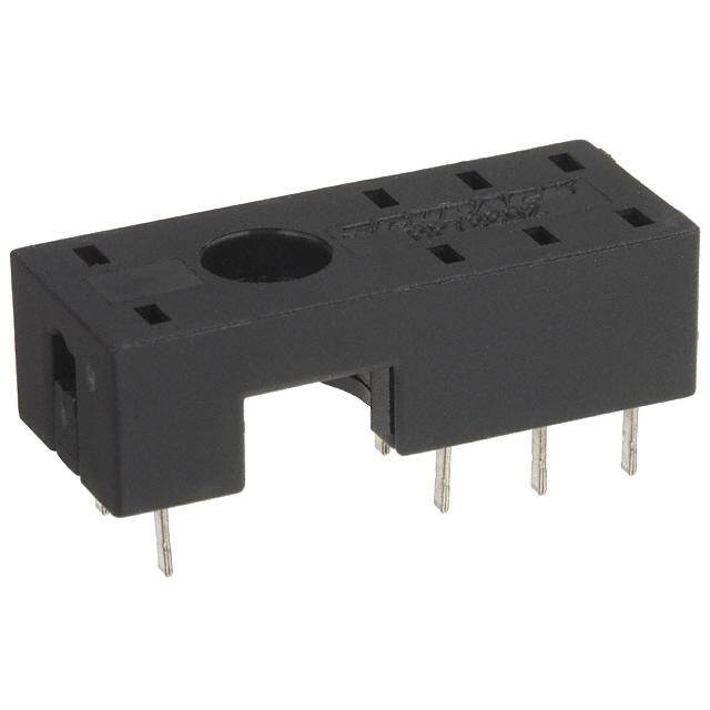
G3DZ Solid State Relays ■Dimensions (Unit: mm) G3DZ-2R6PL Mounting Holes Terminal Arrangement/ G3DZ-1R5PL(G) (BOTTOM VIEW) Internal Connections Tolerance: ±0.1 mm (BOTTOM VIEW) G3DZ-DZ02P(G) G3DZ-2R6PL/-1R5PL(G) Four, 0.5 17.5 6.5 1.1 dia. Load power (1.13) holes 2.54 supply LOAD (0.71) − 12.5 max. − 1 5 7 Input 5.08 2.54 voltage IN+PUT LOAD 13 3.5 + 0.5 0.8 0.3 15.24 G3DZ-DZ02P(G) 2.54 7.62 5.08 5.08 Load power supply LOAD The above diagram is a − − 1 −5 7+ G3DZ-2R6PL Relay. Input voltage IN+PUT LOAD 13 Note: Orientation marks are indicated as follows: + The load can be connected to either the positive or negative side. ■Socket Use the socket P6D-04P. P6D-04P Mounting Holes 19.7 max. (BOTTOM VIEW) Tolerance: ±0.1 mm Socket Mounting Hight 6.9 max. Four 1.1-dia. (2.18) holes 2.54 (0.86) 18.5 mm 6±0.1 10.8 5.08 2.54 max. G 3.6 3 15.24 D 0.65 0.3 Z 2.54 7.62 5.08 ■Safety Precautions (cid:129)Please refer to “Solid State Relays Common Precautions” for correct use. Precautions for Correct Use (cid:129)Reversed Surge Voltage (cid:129)Representative Example of Relay (cid:129)SSR Mounting (cid:120)If any reversed surge voltage is Driver Circuit (cid:120)Do not wash or solder the PCB while imposed on the input terminals, insert (For C-MOS) the SSR is mounted in the Socket. a diode in parallel to the input CC--MMOOSS ++VVCCCC terminals. Do not impose a reversed RR11 1133 55 voltage value of 3 V or more. LOAD VVFF 11 77 − 1 5 7 VVIINN VVOOLL//OOHH INPUT LOAD + 13 (For transistors) (cid:129)Terminals (cid:120)Since terminals are made of materials +VCC with high heat conduction, complete soldering (automatic or manual) with 10~100 kΩ R1 13 5 LOAD 10 seconds at a temperature of 260°C. VF 1 When fitting with a Socket, match 7 properly and push straight down VIN VOL/OH vertically. (cid:129)Calculation of Input Resistance R1 = VCC−4V~O5L0− VmFA (ON) 4
G3DZ Solid State Relays G 3 D Z (cid:129) Application examples provided in this document are for reference only. In actual applications, confirm equipment functions and safety before using the product. (cid:129) Consult your OMRON representative before using the product under conditions which are not described in the manual or applying the product to nuclear control systems, railroad systems, aviation systems, vehicles, combustion systems, medical equipment, amusement machines, safety equipment, and other systems or equipment that may have a serious influence on lives and property if used improperly. Make sure that the ratings and performance characteristics of the product provide a margin of safety for the system or equipment, and be sure to provide the system or equipment with double safety mechanisms. Note: Do not use this document to operate the Unit. OMRON Corporation Electronic and Mechanical Components Company Contact: www.omron.com/ecb Cat. No. K089-E1-07 0616(0207)(O) 5
Mouser Electronics Authorized Distributor Click to View Pricing, Inventory, Delivery & Lifecycle Information: O mron: P6D-04P