ICGOO在线商城 > 射频/IF 和 RFID > RF 天线 > P522304
- 型号: P522304
- 制造商: Ethertronics Inc
- 库位|库存: xxxx|xxxx
- 要求:
| 数量阶梯 | 香港交货 | 国内含税 |
| +xxxx | $xxxx | ¥xxxx |
查看当月历史价格
查看今年历史价格
P522304产品简介:
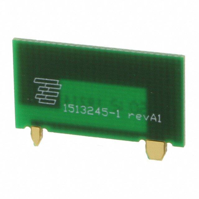
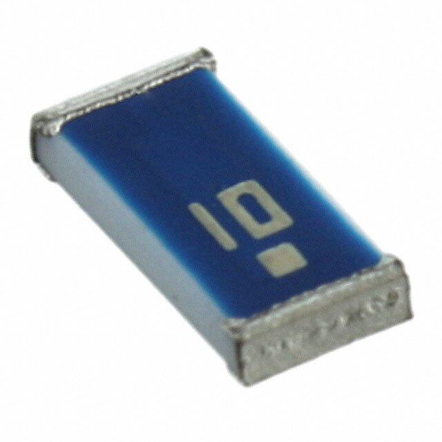
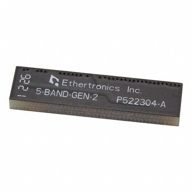
ICGOO电子元器件商城为您提供P522304由Ethertronics Inc设计生产,在icgoo商城现货销售,并且可以通过原厂、代理商等渠道进行代购。 P522304价格参考¥10.82-¥10.82。Ethertronics IncP522304封装/规格:RF 天线, 850MHz,900MHz,1.8GHz,1.9GHz,2.1GHz CDMA,DCS,GSM,PCS,UMTS,WCDMA 芯片 RF 天线 824MHz ~ 960MHz,1.71GHz ~ 2.17GHz 1.4dBi,1.2dBi,1.8dBi,1.1dBi,2.5dBi 焊接 表面贴装。您可以下载P522304参考资料、Datasheet数据手册功能说明书,资料中有P522304 详细功能的应用电路图电压和使用方法及教程。
| 参数 | 数值 |
| 产品目录 | |
| 描述 | CELL ANTENNA 5-BAND 35X9X3.2MM |
| 产品分类 | |
| 品牌 | Ethertronics Inc |
| 数据手册 | |
| 产品图片 |
|
| 产品型号 | P522304 |
| rohs | 无铅 / 符合限制有害物质指令(RoHS)规范要求 |
| 产品系列 | Prestta |
| VSWR | 2.5 |
| 其它名称 | 939-1022-1 |
| 包装 | 剪切带 (CT) |
| 增益 | 1.4dBi,1.2dBi,1.8dBi,1.1dBi,2.5dBi |
| 天线类型 | FR4 |
| 安装类型 | 表面贴装 |
| 标准包装 | 1 |
| 端接 | 表面贴装型 |
| 频带数 | 5 |
| 频率 | 850MHz,900MHz,1.8GHz,1.9GHz,2.1GHz |
| 高度(最大值) | 0.126"(3.20mm) |




- 商务部:美国ITC正式对集成电路等产品启动337调查
- 曝三星4nm工艺存在良率问题 高通将骁龙8 Gen1或转产台积电
- 太阳诱电将投资9.5亿元在常州建新厂生产MLCC 预计2023年完工
- 英特尔发布欧洲新工厂建设计划 深化IDM 2.0 战略
- 台积电先进制程称霸业界 有大客户加持明年业绩稳了
- 达到5530亿美元!SIA预计今年全球半导体销售额将创下新高
- 英特尔拟将自动驾驶子公司Mobileye上市 估值或超500亿美元
- 三星加码芯片和SET,合并消费电子和移动部门,撤换高东真等 CEO
- 三星电子宣布重大人事变动 还合并消费电子和移动部门
- 海关总署:前11个月进口集成电路产品价值2.52万亿元 增长14.8%

PDF Datasheet 数据手册内容提取
DATASHEET Part No. P522304 Product: Broadband FR4 Embedded Cellular Antenna Part No. P522304 Broadband FR4 Embedded Cellular Antenna 850 / 900 / 1800 / 1900 / 2100 MHz Supports: Broadband LTE (OCTA-BAND), LTE CAT-M, NB-IoT, SigFox, LoRa, Cellular LPWA, RPMA, Firstnet Ethertronics’ Broadband Embedded Cellular antenna utilizes Isolated Magnetic Dipole™ (IMD) technology which address the challenges facing today’s product designers. IMD’shigh performance and isolation characteristics offer better connectivity and minimal interference. Stays in Tune IMDantenna technology provides superior RFfield containment, resulting in less interaction with surrounding components. Ethertronics IMDantennas resist detuning; providing a robust radio link regardless of the usage position Broadband FR4 Embedded Cellular Antenna Ethertronics antennas use patented IMDtechnology in many antenna configurations to provide high performance. IMDantennas requires a Low Band 824 –960 MHz smaller design keep-out area, carry lower program development risk which High Band 1710 - 2170 MHz yields a quicker time-to-market, without sacrificing RFperformance. Electrical Specifications KEY BENEFITS Typical Characteristics, on 50 x 110 mm PCB Reduced Costs and Frequency 824-960 MHz 1710-2170 MHz Time-to-Market Standard antenna eliminates Efficiency 62% 55% design fees and cycle time VSWR 2.5:1max 2.7:1 max associated with a custom solution; getting products to market faster. Peak Gain 0 dBi 0.7 dBi Greater Flexibility with Unique Form Factors Polarization Linear Ethertronics’ technology helps you deliver more advanced ergonomic Power Handling 2 Watts CW designs without adverse impact Radiation Pattern Omni-directional on product performance. Reliability Feed Point Impedance 50 ohms unbalanced Comply with latest RoHS requirements Mechanical Specifications & Ordering Part Number APPLICATIONS Ordering Part# P522304 • Medical • Automotive applications • Healthcare Dimensions(mm) 35.0 x 9.0 x 3.2 • Home • Point of Sale automation • Tracking Weight (grams) 2.1 • Smart • Cellular metering • 3GSystems Mounting SMT(P&P) • M2M, Industrial devices Packaging 1,120 pcs/reel; 5,600 pcs/box • IoT • Firstnet Demo Board P522304-02 11/27/2018 Proprietary www.ethertronics.com
DATASHEET | Part No. P522304 Cellular FR4Ethertronics’ Embedded Antenna Specifications. Ethertronics produces a wide variety of standard and custom antennas to meet user needs. Antenna Dimensions Typical antenna dimensions (mm) Part Number A (mm) B (mm) C (mm) P522304 35.0 ±0.3 9.0 ±0.2 3.2 ±0.3 A B Top View C Height Pin #3 Pin #4 Pin Descriptions Pin #2 Pin# Description 1 Feed 2 Ground 3 Dummy Pad 4 Dummy Pad Pin #1 Pin #5 5 Low BandTuning Bottom View tel +(1) 858.550.3820 | fax +(1) 858.550.3821 © 2018 Ethertronics email: eth.info@avx.com 5501 OberlinDrive, Suite 100 San Diego, CA 92121 -USA
DATASHEET | Part No. P522304 Cellular FR4Ethertronics’ Embedded Antenna Specifications. Ethertronics produces a wide variety of standard and custom antennas to meet user needs. VSWR and Efficiency Plots (Off-Ground) Typical Performance on 50 x 110 mm PCB 2 50 0 - 4 0 3 2 2 5 110 P Low Band VSWR High Band VSWR Low Band Efficiency High Band Efficiency tel +(1) 858.550.3820 | fax +(1) 858.550.3821 © 2018 Ethertronics email: eth.info@avx.com 5501 OberlinDrive, Suite 100 San Diego, CA 92121 -USA
DATASHEET | Part No. P522304 Cellular FR4Ethertronics’ Embedded Antenna Specifications. Ethertronics produces a wide variety of standard and custom antennas to meet user needs. Antenna Radiation Patterns Typical Performance on 50 x 110 mm PCB Measured @ 910, 1870 MHz z H M 0 1 9 t a d e r u s a e M z H M 0 7 8 1 t a d e r u s a e M tel +(1) 858.550.3820 | fax +(1) 858.550.3821 © 2018 Ethertronics email: eth.info@avx.com 5501 OberlinDrive, Suite 100 San Diego, CA 92121 -USA
DATASHEET | Part No. P522304 Cellular FR4Ethertronics’ Embedded Antenna Specifications. Ethertronics produces a wide variety of standard and custom antennas to meet user needs. Antenna Layout (On-Ground) Typical layout dimensions (mm) Pin #2 S2 S1 P2 Pin #5 P1 Pin #1 Pin #4 Pin #3 VIAs * VIAS: Diam. 0.2mm, (no viason transmission lines). Via holes must be covered by solder mask Pin Descriptions 50Ω Transmission Pin# Description Line 1 Feed 2 Ground 3 Dummy Pad 4 Dummy Pad 5 Low BandTuning Matching & Tuning Component Values Antenna Component Value Tolerance Outline P1 3.6nH ±0.05nH S1 1.2pF ±0.05pF S2 15nH ±0.3nH P2 1.8pF ±0.05pF R1 –R7 DNI N/A Default Pi Matching Network values and (R1-R7) tuning instructions can be found under Antenna Matching Structure.. R1 R6 R4 R3 R2 R7 R5 tel +(1) 858.550.3820 | fax +(1) 858.550.3821 © 2018 Ethertronics email: eth.info@avx.com 5501 OberlinDrive, Suite 100 San Diego, CA 92121 -USA
DATASHEET | Part No. P522304 Cellular FR4Ethertronics’ Embedded Antenna Specifications. Ethertronics produces a wide variety of standard and custom antennas to meet user needs. Antenna Matching Structure Typical matching values on 50 x 110 mm PCB Demo Board Front View Demo Board Back View Pin #2 Pin #5 Pin #1 Vias Pin #4 Pin #3 Antenna Matching Low Band Tuning Tune Low Band Higher Tune Low Band Lower (Cut Bridge Trace) (Add 0Ω) [ P 2 [ S2 ] ] [ S1 ] [ P1 [ R 1 ] ] [ R2 ][ R3 ][ R4 ][ R15][ R6 ] [ R7 ] (Antenna Matching): *Cut Trace between pads shifts resonant frequency *Bridging gaps with 0 ohm resistors shifts resonant pads are directly inline with higher frequency lower the antenna feed trace. Pin Descriptions (Low Band Tuning) Pin# Description 1 Feed R1 R2 R3 R4 R5 R6 R7 2 Ground 3 Dummy Pad 1 2 3 4 5 4 Dummy Pad 5 Low BandTuning P2 P1 50ohm (Antenna Matching) S2 S1 P1 S1 S2 P2 (R1-R7) Default Matching 3.6nH 1.2pF 15nH 1.8pF DNI Tolerance ±0.05nH ±0.05pF ±0.3nH ±0.05pF N/A tel +(1) 858.550.3820 | fax +(1) 858.550.3821 © 2018 Ethertronics email: eth.info@avx.com 5501 OberlinDrive, Suite 100 San Diego, CA 92121 -USA
DATASHEET | Part No. P522304 Cellular FR4Ethertronics’ Embedded Antenna Specifications. Ethertronics produces a wide variety of standard and custom antennas to meet user needs. Antenna Demo Board Demo Board Front View/Back View Part Number A (mm) B (mm) C (mm) P522304-02 110 50.0 15.0 C Antenna Outline A P522304-02 B Front View Back View tel +(1) 858.550.3820 | fax +(1) 858.550.3821 © 2018 Ethertronics email: eth.info@avx.com 5501 OberlinDrive, Suite 100 San Diego, CA 92121 -USA
DATASHEET | Part No. P522304 Cellular FR4Ethertronics’ Embedded Antenna Specifications. Ethertronics produces a wide variety of standard and custom antennas to meet user needs. Recommended Reflow Soldering Profile The recommended method for soldering the antenna to the board is forced convection reflow soldering. The following suggestions provide information on how to optimize the reflow process for the FR4antenna: *Adjust the reflow duration to create good solder joints without raising the antenna temperature beyond the allowed maximum of 260°C. tel +(1) 858.550.3820 | fax +(1) 858.550.3821 © 2018 Ethertronics email: eth.info@avx.com 5501 OberlinDrive, Suite 100 San Diego, CA 92121 -USA
 Datasheet下载
