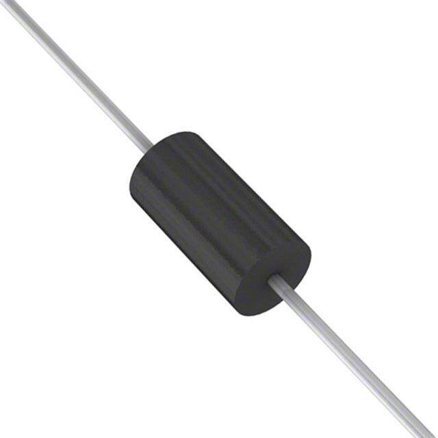
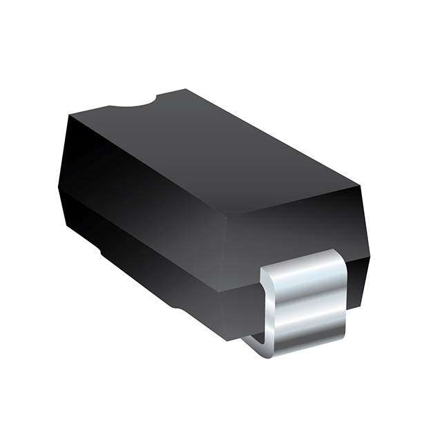
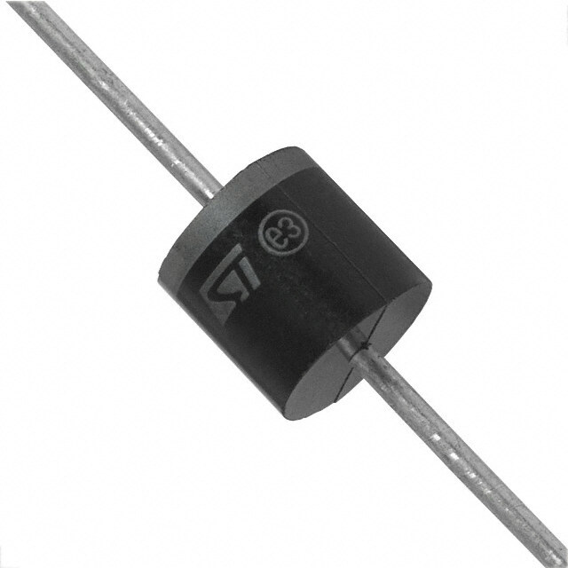
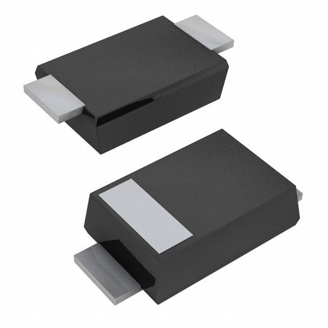
- 型号: P4SMA400A
- 制造商: Littelfuse
- 库位|库存: xxxx|xxxx
- 要求:
| 数量阶梯 | 香港交货 | 国内含税 |
| +xxxx | $xxxx | ¥xxxx |
查看当月历史价格
查看今年历史价格
P4SMA400A产品简介:
ICGOO电子元器件商城为您提供P4SMA400A由Littelfuse设计生产,在icgoo商城现货销售,并且可以通过原厂、代理商等渠道进行代购。 P4SMA400A价格参考。LittelfuseP4SMA400A封装/规格:TVS - 二极管, 。您可以下载P4SMA400A参考资料、Datasheet数据手册功能说明书,资料中有P4SMA400A 详细功能的应用电路图电压和使用方法及教程。
| 参数 | 数值 |
| 产品目录 | |
| 描述 | TVS DIODE 342VWM 548VC SMDTVS 二极管 - 瞬态电压抑制器 342Vso 380Vbr |
| 产品分类 | |
| 品牌 | Littelfuse |
| 产品手册 | |
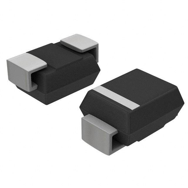
| 产品图片 |
|
| rohs | 符合RoHS不受无铅要求限制 / 符合限制有害物质指令(RoHS)规范要求 |
| 产品系列 | 二极管与整流器,TVS二极管,TVS 二极管 - 瞬态电压抑制器,Littelfuse P4SMA400AP4SMA |
| 数据手册 | |
| 产品型号 | P4SMA400A |
| 不同频率时的电容 | - |
| 产品培训模块 | http://www.digikey.cn/PTM/IndividualPTM.page?site=cn&lang=zhs&ptm=22970 |
| 产品种类 | TVS 二极管 - 瞬态电压抑制器 |
| 供应商器件封装 | DO-214AC(SMA) |
| 其它名称 | P4SMA400A-ND |
| 击穿电压 | 380 V |
| 功率-峰值脉冲 | 400W |
| 包装 | 带卷 (TR) |
| 单向通道 | 1 |
| 双向通道 | - |
| 商标 | Littelfuse |
| 安装类型 | 表面贴装 |
| 安装风格 | SMD/SMT |
| 封装 | Reel |
| 封装/外壳 | DO-214AC,SMA |
| 封装/箱体 | DO-214AC |
| 尺寸 | 2.79 mm W x 4.5 mm L x 2.29 mm H |
| 峰值浪涌电流 | 800 mA |
| 峰值脉冲功率耗散 | 400 W |
| 工作温度 | -55°C ~ 150°C |
| 工作电压 | 342 V |
| 工厂包装数量 | 5000 |
| 应用 | 通用 |
| 最大工作温度 | + 150 C |
| 最小工作温度 | - 65 C |
| 极性 | Unidirectional |
| 标准包装 | 5,000 |
| 电压-击穿(最小值) | 380V |
| 电压-反向关态(典型值) | 342V |
| 电压-箝位(最大值)@Ipp | 548V |
| 电流-峰值脉冲(10/1000µs) | 800mA |
| 电源线路保护 | 无 |
| 端接类型 | SMD/SMT |
| 类型 | 齐纳 |
| 系列 | P4SMA |
| 钳位电压 | 548 V |




- 商务部:美国ITC正式对集成电路等产品启动337调查
- 曝三星4nm工艺存在良率问题 高通将骁龙8 Gen1或转产台积电
- 太阳诱电将投资9.5亿元在常州建新厂生产MLCC 预计2023年完工
- 英特尔发布欧洲新工厂建设计划 深化IDM 2.0 战略
- 台积电先进制程称霸业界 有大客户加持明年业绩稳了
- 达到5530亿美元!SIA预计今年全球半导体销售额将创下新高
- 英特尔拟将自动驾驶子公司Mobileye上市 估值或超500亿美元
- 三星加码芯片和SET,合并消费电子和移动部门,撤换高东真等 CEO
- 三星电子宣布重大人事变动 还合并消费电子和移动部门
- 海关总署:前11个月进口集成电路产品价值2.52万亿元 增长14.8%




PDF Datasheet 数据手册内容提取
NT *RoHS VCEOARVMSIAPILOLINAASBLE Features Applications NT MPLIA n RoHS compliant* and halogen free** n IEC 61000-4-2 ESD (Min. Level 4) O HS C n Surface Mount SMA package n IEC 61000-4-4 EFT Ro * n Breakdown Voltage: 6.8 to 550 volts n IEC 61000-4-5 Surge n Peak Pulse Power: 400 watts n Typical temperature coefficient: ∆VBR = 0.1 % x VBR @ 25 °C x ∆T REE D F LEA P4SMA Transient Voltage Suppressor Diode Series General Information TiBnhoceure rmnassa irnokgfefeltysr s so mTf rapalonlerstrai eebnlleet c Vctrooolmtnaimgc euc onSmiucapptpoiornenessns,t oscLr.VoER EADomRDH SIiSF poORCNuEdOSE teMAiPnsRLIEg Af NoaTr*n sdu vrgidee aon edq EuiSpDm epnrot taercet iochna allpepnlgicinagtio tnhse, sine mcoicmopnadcutc ctohri pin pdaucsktrayg teo DdOev-e2l1o4pA C (SMA) size format. The Transient Voltage Suppressor series offers a choice of Breakdown Voltages from 6.8 V up to 550 V. Typical fast response times are less than 1.0 picosecond for unidirectional devices and less than 5.0 picoseconds for bidirectional devices. Bourns® Chip Diodes conform to JEDEC standards, are easy to handle with standard pick and place equipment and the flat configuration minimizes roll away. Maximum Ratings (@ TA = 25 °C Unless Otherwise Noted) Parameter Symbol Value Unit Peak Pulse Power Dissipation (TP = 1 ms) (Note 1,2) PPK 400 Watts Peak Forward Surge Current 8.3 ms Single Half Sine Wave Superimposed on Rated Load IFSM 40 Amps (JEDEC Method) (Note 3) Instantaneous Forward Voltage @ 25 A P4SMA6.8A ~ P4SMA200A 3.5 (For Unidirectional Units Only) P4SMA220A ~ P4SMA550A VF 5.0 Volts Operating Temperature Range TJ -55 to +150 °C Storage Temperature Range TSTG -55 to +150 °C 1. Non-repetitive current pulse, per Pulse Waveform graph and derated above TA = 25 °C per Pulse Derating Curve. 2. Mounted on 5.0 mm x 5.0 mm copper pad to each terminal. 3. 8.3 ms Single Half-Sine Wave duty cycle = 4 pulses maximum per minute (unidirectional units only). How to Order P4SMA 6.8 CA - H Asia-Pacific: Tel: +886-2 2562-4117 Series Email: asiacus@bourns.com P4SMA = SMA/DO-214AC Europe: Breakdown Voltage Tel: +36 88 520 390 6.8 to 550 = 6.8 to 550 VBD (Volts) Suffix Email: eurocus@bourns.com A = 5 % Tolerance Unidirectional Device The Americas: CA = 5 % Tolerance Bidirectional Device Tel: +1-951 781-5500 Reel Email: americus@bourns.com (blank) = 13 inch reel -H = 7 inch reel www.bourns.com * RoHS Directive 2002/95/EC Jan. 27, 2003 including annex and RoHS Recast 2011/65/EU June 8, 2011. **Bourns considers a product to be “halogen free” if (a) the Bromine (Br) content is 900 ppm or less; (b) the Chlorine (Cl) content is 900 ppm or less; and (c) the total Bromine (Br) and Chlorine (Cl) content is 1500 ppm or less. Specifications are subject to change without notice. The device characteristics and parameters in this data sheet can and do vary in different applications and actual device performance may vary over time. Users should verify actual device performance in their specific applications.
P4SMA Transient Voltage Suppressor Diode Series Electrical Characteristics (@ TA = 25 °C Unless Otherwise Noted) Working Maximum Maximum Maximum Breakdown Voltage Peak Reverse Reverse Reverse Unidirectional Device Bidirectional Device VBR (Volts) Reverse Leakage Voltage Surge Voltage @ VRWM @ IRSM Current Part No. Marking Part No. Marking Min. Max. @ IT (mA) VRWM (V) IR (μA) VRSM (V) IRSM (A) P4SMA6.8A 6V8A P4SMA6.8CA 6V8C 6.45 7.14 10 5.8 1000 10.5 39 P4SMA7.5A 7V5A P4SMA7.5CA 7V5C 7.13 7.88 10 6.4 500 11.3 36.3 P4SMA8.2A 8V2A P4SMA8.2CA 8V2C 7.79 8.61 10 7.02 200 12.1 33.9 P4SMA9.1A 9V1A P4SMA9.1CA 9V1C 8.65 9.55 1 7.78 50 13.4 30.6 P4SMA10A 10A P4SMA10CA 10C 9.5 10.5 1 8.55 10 14.5 28.3 P4SMA11A 11A P4SMA11CA 11C 10.5 11.6 1 9.4 5 15.6 26.3 P4SMA12A 12A P4SMA12CA 12C 11.4 12.6 1 10.2 5 16.7 24.6 P4SMA13A 13A P4SMA13CA 13C 12.4 13.7 1 11.1 1 18.2 22.5 P4SMA15A 15A P4SMA15CA 15C 14.3 15.8 1 12.8 1 21.2 19.3 P4SMA16A 16A P4SMA16CA 16C 15.2 16.8 1 13.6 1 22.5 18.2 P4SMA18A 18A P4SMA18CA 18C 17.1 18.9 1 15.3 1 25.5 16.1 P4SMA20A 20A P4SMA20CA 20C 19 21 1 17.1 1 27.7 14.8 P4SMA22A 22A P4SMA22CA 22C 20.9 23.1 1 18.8 1 30.6 13.4 P4SMA24A 24A P4SMA24CA 24C 22.8 25.2 1 20.5 1 33.2 12.3 P4SMA27A 27A P4SMA27CA 27C 25.7 28.4 1 23.1 1 37.5 10.9 P4SMA30A 30A P4SMA30CA 30C 28.5 31.5 1 25.6 1 41.4 9.9 P4SMA33A 33A P4SMA33CA 33C 31.4 34.7 1 28.2 1 45.7 9 P4SMA36A 36A P4SMA36CA 36C 34.2 37.8 1 30.8 1 49.9 8.2 P4SMA39A 39A P4SMA39CA 39C 37.1 41 1 33.3 1 53.9 7.6 P4SMA43A 43A P4SMA43CA 43C 40.9 45.2 1 36.8 1 59.3 6.9 P4SMA47A 47A P4SMA47CA 47C 44.7 49.4 1 40.2 1 64.8 6.3 P4SMA51A 51A P4SMA51CA 51C 48.5 53.6 1 43.6 1 70.1 5.8 P4SMA56A 56A P4SMA56CA 56C 53.2 58.8 1 47.8 1 77 5.3 P4SMA62A 62A P4SMA62CA 62C 58.9 65.1 1 53 1 85 4.8 P4SMA68A 68A P4SMA68CA 68C 64.6 71.4 1 58.1 1 92 4.5 P4SMA75A 75A P4SMA75CA 75C 71.3 78.8 1 64.1 1 103 4 P4SMA82A 82A P4SMA82CA 82C 77.9 86.1 1 70.1 1 113 3.6 P4SMA91A 91A P4SMA91CA 91C 86.5 95.5 1 77.8 1 125 3.3 P4SMA100A 100A P4SMA100CA 100C 95 105 1 85.5 1 137 3 P4SMA110A 110A P4SMA110CA 110C 105 116 1 94 1 152 2.7 P4SMA120A 120A P4SMA120CA 120C 114 126 1 102 1 165 2.5 P4SMA130A 130A P4SMA130CA 130C 124 137 1 111 1 179 2.3 P4SMA150A 150A P4SMA150CA 150C 143 158 1 128 1 207 2 P4SMA160A 160A P4SMA160CA 160C 152 168 1 136 1 219 1.9 P4SMA170A 170A P4SMA170CA 170C 162 179 1 145 1 234 1.8 P4SMA180A 180A P4SMA180CA 180C 171 189 1 154 1 246 1.7 P4SMA200A 200A P4SMA200CA 200C 190 210 1 171 1 274 1.5 P4SMA220A 220A P4SMA220CA 220C 209 231 1 185 1 328 1.3 P4SMA250A 250A P4SMA250CA 250C 237 263 1 214 1 344 1.2 P4SMA300A 300A P4SMA300CA 300C 285 315 1 256 1 414 1 P4SMA350A 350A P4SMA350CA 350C 332 368 1 300 1 482 0.9 P4SMA400A 400A P4SMA400CA 400C 380 420 1 342 1 548 0.8 P4SMA440A 440A P4SMA440CA 440C 418 462 1 376 1 602 0.7 P4SMA480A 480A P4SMA480CA 480C 456 504 1 408 1 658 0.6 P4SMA510A 510A P4SMA510CA 510C 485 535 1 434 1 698 0.6 P4SMA530A 530A P4SMA530CA 530C 503.5 556.5 1 477 1 725 0.6 P4SMA540A 540A P4SMA540CA 540C 513 567 1 486 1 740 0.5 P4SMA550A 550A P4SMA550CA 550C 522.5 577.5 1 495 1 760 0.5 Notes: 1. Suffix ‘A’ denotes a 5 % tolerance unidirectional device. 3. For bidirectional devices with a VR of 10 volts or less, the IR limit is double. 2. Suffix ‘CA’ denotes a 5 % tolerance bidirectional device. Specifications are subject to change without notice. The device characteristics and parameters in this data sheet can and do vary in different applications and actual device performance may vary over time. Users should verify actual device performance in their specific applications.
3P34S12M A- 2T rmanmsi SenMt DV oTltraimgem Siunpgp Preostseonrt iDoimodeete Sreries Rating & Characteristic Curves PulPeak Pulse Derating in Percent ofsPeak Pulse Derating in Percent ofPeak Pulse Derating in Percent ofePeak Pulse Derating in Percent ofPeak Power or CurrentPeak Power or Current DPeak Power or CurrentPeak Pulse Derating in Percent ofPeak Power or Current1Peak Pulse Derating in Percent of1e7520752011Peak Power or Current50500r505075200Peak Power or Current75200a50500505001t107520i752050500n505000g0 2C52u5r2v25e55050550075757751501000110001021525112251551050115501071575117752502000220000 MPeak Forward Surge Current (Amps)aPeak Forward Surge Current (Amps)Peak Forward Surge Current (Amps)xPeak Forward Surge Current (Amps)im432165Peak Forward Surge Current (Amps)4321650Peak Forward Surge Current (Amps)0000000000043210043216565u001000000000000m4321651432165000000000000 00N11oS2SniPinPSS2nu-guiPiPgnRlnllsuSulesg2geeSl2 eleiPlls Hs neeiPH WeunpeW g auHa H lgllWisWellfeidlaasf dee SttlleiHi St fhfddiWHh i 5tinaSW tStn 8haihle8iiif5evd.ln ni - .f3d88-St3W eeeWh St..-i m-53h3nm WiaW58na Sevsm8m.vse-aae3.ueW-v3svs Wmee ram1gavs0vse1ee0 C110u02r0r2e0n220t0 50505500 101000110000 00 2525 505A0mAbmiAeb7Anmi57met5 bnTbitee iTemn1netp 01mtT e00Tepr0emaemtrpuapert1eeur2a1r r(aet52°ut C5u(r°)erCe ( )1°(°C51C0)5)0 171575 202000 11 22 5N5uNmubmNNeubrum eomrbf 1 boeC01efry r0Coc oylfe fcC slCey ay2sctc l0 2eal6e0st0 s 6 a H0at t z6 H60z0 H Hzz5050 101000 AAmmbibeinetn Tt eTmempepreartautruer e( °(C°C)) NNumumbebre or fo Cf yCcylcelse sa ta 6t 06 0H Hzz Pulse Waveform Typical Junction Capacitance 151050115500 10010000010100000000 I - Peak Pulse Current, % II - Peak Pulse Current, % IPPMRSMPPMRSMI - Peak Pulse Current, % II - Peak Pulse Current, % IPPMRSMPPMRSM1I - Peak Pulse Current, % I115I - Peak Pulse Current, % IPPMRSM05050110PPMRSM010050050500000000001051000500000000ttddtttddtrr = tt=rt r1 d t1==0P d0 IP 1t PeI1µ PerP0atP 1µ0PP sMaIr1kI=s MPe.ek Peµ Pµ=.0eaVP1c a110sMVc ksM.ak01.eP . .eal 0IVHc00uVP clPeHuIµ.aPe.aaa Pe1easMµllkPHlau1Hfu.lesM fke0aVVcea .e Vl0.Vlacaff al.l aVHuuVlltuHaeaueat ell-ea l-ufu- t- ltI efVe I PT 2 ---VPaTP2- PMI liaI uMPmiT22PtlT2mPe2uP .tMi-Mei-.0 me 2m20-I e-1a P.T2.I1a s 0(0Pe0PT2es(0M im/P1ad 1am1m2/ Mdis1(0es(00m2TPap5.e fms0/ Pap5Tmd/00sie0ed1fsu.J1n0sie0ue) 00aJ e0n1ael TPap5t 0)e 0%TPap5as f=slk htfss0(e01as%sie0=dµ0u skeJhie0u nJe ndµ)s m0/e(0ac2 ) 0 lsd aet l1 eo %tsbc2 W= e sk%hsum/=5pekohe dbWdµ01feuyTPap55dµp eeer c o fsfeec2 y si0 c20 s rrIice0 TPap5so ou bJd.W°oRin ifusb PrW5eIpe )u 0 5n0ad. pse °ie0Ri fl u Pyte tJWPf e n rn%yns c . o= Crkh) hct 0t o aWPi M E nlr I.ditµ C rheedIt.t%°s Ri=Md.E Pkee°hRwi a Pne.t c2 ( sdµn te WP3dw Aao nt. WbP.eWv(tnChut.53c2d pehACMh Et sdvMetE fo.t ye.bhW t rudcw 5eo aepe ..we.c0)a( i. ffrI(3dyAed3d.rc0Av)r °tc Rio oafPevth iin d hrr e eI o. adte. eWds.P°y.rRinie..PeeeC h t cn0s)e MyrmE fc0 ) st WPtf tn r .dom aC hr stwhoata Mi. Ee(di ets3dhAtyer s vytrwea .ohte(m sdfe3dmtAe .se.otdvtidfheh hc0)dne fi.e.tert enoeeaoc0e)eioffefsre yroiadii nem sndstyrd he m estteddhed ofteeionfiende4d4..0440..0044.0.0 C Junction Capacitance (pF) - C Junction Capacitance (pF) J - JC Junction Capacitance (pF) C Junction Capacitance (pF) - J - JC Junction Capacitance (pF) - JC Junction Capacitance (pF) 11 - J1001100101101001000000010100100101001010000001010110110011000100010TfV001TfV 1=s J1=sJ iTfV TfV=g i1 =g=s1=sJ J.2= Ui 0 .i =g2=U=g1015 TfVn5 5 M . .n 2=5TfVU2=M0=siU0J°0 d i 5° 0 =iH5s dJ n C n 5=g5MiH1M mC i riizi=g°0m 1°0.rde dz 2= UH0He C V C. cii2=m5 VUm0 rcrnz5zptMe5 e pitni5°0V-oMVicdc -oHip°0C nptdpit p mHniriC za-oi-oemrazplpVncne l@V aptc1a@ilpt-lo0 V ip@-oV@n1RpBnRa0BVVlai diRRl@BdB1 i@rii1i0rVdede0VciRirBcrtReeBitioidccointditnriiaoioeralncne lV tacaViB ltloB = iiVo=Vndi BdB0n a i0==rii ilardeVd leVV00ci iBrUcVr 1t UeVe=VBiti no0idcc= noiUiU0ntd10itd inrii0d nanioo0ieVrar iliincneVr 0deldU@ e1tcaac@iiiUrcnr1tllo0tV e ieitni@oV@0no0idccRoinRa0ndtitVVnriilaaioo eRRral@ln cne l@V tcaaVVi tlolVR = iVo=VnR 0n a 0== la V lVV00 V =VV = 10 0 0V 10V000101000000 11 VBVRB VR-V BR -BR e1RRv0 1-e e0 -vrR sReeerevs vBeeerr sBreseare ekB adBrkoerdewaoaknwkd dVon1oow0 1Vw0l0ntoan0 lVg tVaeogo l(telVat ag()gVee )( V(V)) 10100000 VVBRBR - -R Reveevresres eB rBeraekadkodwown nV oVlotaltgaeg e(V ()V) Pulse Rating Curve Steady State Power Derating Curve 101000110000 1.01.011.0.0 P, Peak Power (KW)P, Peak Power (KW)PPP, Peak Power (KW)P, Peak Power (KW)PP101P, Peak Power (KW)101P1..01P, Peak Power (KW)..10001P1000110001....0010.00110101 10...µ11001..0s001 0µ.1.s1 µ µss1.01 .µ01s 1µ.0.s0 µ µss101 µ0s S1µS10hsShS0 ooµh hwµwsooSsnwSwnh 1h inoninP0on Pw 1 iNi0uw PnNPnuPP0n loT uN nlsoµuNT0 PuusP1nAile nslAoT1n lolseTuPi0su-sµs n-nPA0e r=WnNAle0uleerP=Wss esN -0u - eP l oWT e2r=Wpueasr=µWW 2lopTaeun Aesµ5 elve sW5neasv2WApa2pl-easat e stveer =W-i°5ev 5evvfit°aeer=Wae fCtot ei 1tee CWeoviv2 pi°vaf i°fvrtWff.t2poeeCaro5eeCivm0ooie1avmv5fervfter raro.vemoi°etmme mf0mtvi°erCorif1t vme Comfis1mr G.voefGm0r.o e rrm0sG rGamrma mrpmrpa ashG hpspGrhhar1ap0p1h mh0 1sm100s m mss RM(AV) Steady State Power Dissipation (W)M(AV) Steady State Power Dissipation (W)M(AV) Steady State Power Dissipation (W)RM(AV) Steady State Power Dissipation (W)RM(AV) Steady State Power Dissipation (W)RM(AV) Steady State Power Dissipation (W)00000100000......1.....684200000000000068420......00.....684206842000000000000.....68420.....6842000 25252255506560I0066In n H050dIHId5nn 0 zu6HzHu0d d6c 0RIcz7zRuu0tn I tei5HcncR eRivd7sHvttdsezeueiii5ezvis vu sscsR L et7eLciRitti7oss e iiv5toLvLvetit5asevai1ieeoosdivv eds 0 oiaaeeLos 1t0drdL itoro0voiovaer0r1aed 10od 0o0r0r121525112255151050115500171575117755202000220000 0.01. 1µ sµs 1.10. 0µ sµs 101 0µ sµTsPT, PP,Tu TPPlPsu1,e ,l01P s PW00ueu 0 lµisWl dsseµtei shdW Wthididthth1.10. 0m mss 101 0m mss RR 00 2525 5050TLT, LL,Te7 TLaL57Led,5 a, L TdLee eaTmade1dp m0T1 eT0e0prema0emtrpuaperteeurar r1(aet°u2t1 Cu(r52°e)r5Ce ( )°(°CC)1)51050 171575 202000 TPTP, P, Pulusles eW Widitdhth TLT,L L, eLaeda dT eTmempepreartautruer e(° (C°)C) Specifications are subject to change without notice. The device characteristics and parameters in this data sheet can and do vary in different applications and actual device performance may vary over time. Users should verify actual device performance in their specific applications.
P4S3M31A2 T -r a2n msiemn tS VMolDta Tgrei mSumpipnrge sPsootre Dnitoiodme Seeterires Product Dimensions Recommended Footprint CATHODE A A a A BAND (FOR UNIDIRECTIONAL PRODUCTS ONLY) B C B b B c C F D Dimension SMA (DO-214AC) 2.70 a (Max.) G C E (0.106) D 2.10 b (Min.) (0.083) 1.27 c (Min.) DIMENSIONS: MM F (0.050) Dimension SMA ((IDNCOHE-S2)14AC) 3.99 - 4.57 MM A DIMENSIONS: (0.157 - 0.180) (INCHES) E 2.29 - 2.92 B (0.090 - 0.115) 1.25 - 1.65 Physical Specifications C (0.049 - 0.0M6M5) DIME N4S.I8O3NS -: 5(IN.5CH9E S) Case ...........................................Molded plastic per UL Class 94V-0 D Polarity.......................Cathode band indicates unidirectional device (0.190 - 0.220) No cathode band indicates bidirectional device 0.05 - 0.203 E (0.002 - 0.008) 1.98 - 2.62 F Environmental Specifications (0.078 - 0.103) 0.76 - 1.52 Moisture Sensitivity Level ................................................................1 G (0.030 - 0.060) ESD Classification (HBM).............................................................3B MM DIMENSIONS: (INCHES) Specifications are subject to change without notice. The device characteristics and parameters in this data sheet can and do vary in different applications and actual device performance may vary over time. Users should verify actual device performance in their specific applications.
CPD4SDMFNA5 T-0ra5n0s4iNen -t TVVoSlt/aSgteee Sriunpgp Dreisosdoer ADriroadye Series Packaging Information The product will be dispensed in tape and reel format (see diagram below). P 0 P1 E T d Index Hole 120 ° F D2 W B D1 D P A C Trailer Device Leader ....... ....... ....... ....... W1 End ....... ....... ....... ....... Start MM DIMENSIONS: (INCHES) 10 pitches (min.) 10 pitches (min.) Devices are packed in accordance with EIA 481 Direction of Feed standard specifications shown here. Item Symbol SMA (DO-214AC) 7 Inch Reel 13 Inch Reel 2.90 ± 0.20 Carrier Width A (0.114 ± 0.008) 5.50 ± 0.20 Carrier Length B (0.217 ± 0.008) 2.26 ± 0.20 Carrier Depth C (0.089 ± 0.008) 1.50 ± 0.10 Sprocket Hole d (0.061 ± 0.004) 178 330 Reel Outside Diameter D (7.008) (12.992) 50.0 Reel Inner Diameter D1 (1.969) MIN. 13.0 ± 0.20 Feed Hole Diameter D2 (0.512 ± 0.008) 1.75 ± 0.10 Sprocket Hole Position E (0.069 ± 0.004) 5.50 ± 0.05 Punch Hole Position F (0.217 ± 0.002) 4.00 ± 0.10 Punch Hole Pitch P (0.157 ± 0.004) 4.00 ± 0.10 Sprocket Hole Pitch P0 (0.157 ± 0.004) 2.00 ± 0.05 Embossment Center P1 (0.079 ± 0.002) 0.30 ± 0.10 Overall Tape Thickness T (0.012 ± 0.004) 12.00 ± 0.30 Tape Width W (0.472 ± 0.012) 18.4 Reel Width W1 (0.724) MAX. Quantity per Reel -- 1000 5,000 REV. 07/17 Specifications are subject to change without notice. The device characteristics and parameters in this data sheet can and do vary in different applications and actual device performance may vary over time. Users should verify actual device performance in their specific applications.

 Datasheet下载

