ICGOO在线商城 > 传感器,变送器 > 光学传感器 - 光电晶体管 > OP550A
- 型号: OP550A
- 制造商: OPTEK
- 库位|库存: xxxx|xxxx
- 要求:
| 数量阶梯 | 香港交货 | 国内含税 |
| +xxxx | $xxxx | ¥xxxx |
查看当月历史价格
查看今年历史价格
OP550A产品简介:
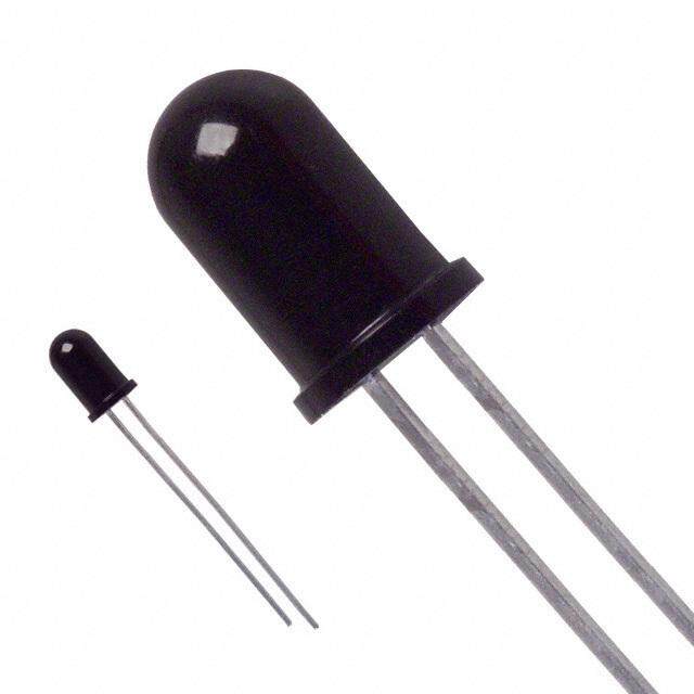
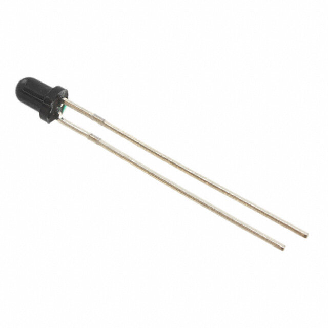
ICGOO电子元器件商城为您提供OP550A由OPTEK设计生产,在icgoo商城现货销售,并且可以通过原厂、代理商等渠道进行代购。 OP550A价格参考。OPTEKOP550A封装/规格:光学传感器 - 光电晶体管, Phototransistor 935nm Side View Radial。您可以下载OP550A参考资料、Datasheet数据手册功能说明书,资料中有OP550A 详细功能的应用电路图电压和使用方法及教程。
| 参数 | 数值 |
| 产品目录 | |
| 描述 | PHOTOTRNSISTR NPN 935NM SIDELOOK光电晶体管 PHOTOSENSOR |
| 产品分类 | |
| 品牌 | TT Electronics/Optek Technology |
| 产品手册 | |
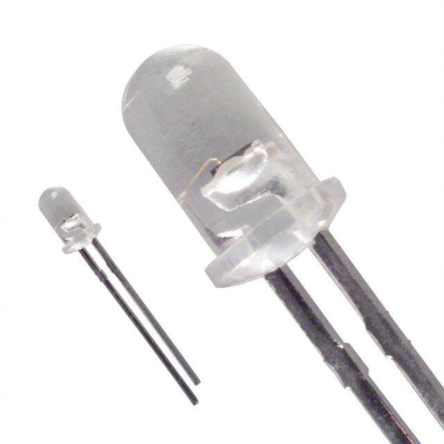
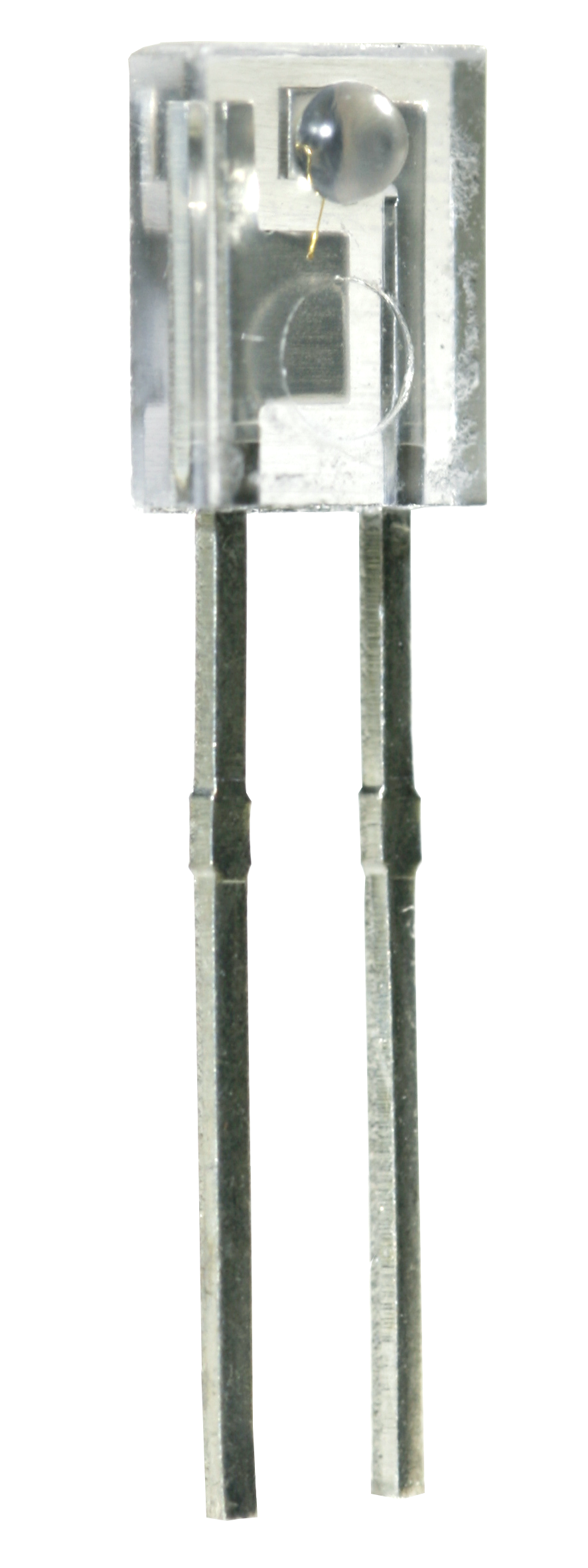
| 产品图片 |
|
| rohs | 符合RoHS无铅 / 符合限制有害物质指令(RoHS)规范要求 |
| 产品系列 | 光电晶体管,Optek / TT Electronics OP550A* |
| 数据手册 | |
| 产品型号 | OP550A |
| 产品 | Phototransistors |
| 产品目录页面 | |
| 产品种类 | 光电晶体管 |
| 其它名称 | 365-1070 |
| 功率-最大值 | 100mW |
| 商标 | Optek / TT Electronics |
| 安装类型 | 通孔 |
| 封装 | Bulk |
| 封装/外壳 | 径向 |
| 封装/箱体 | T-1 |
| 工厂包装数量 | 100 |
| 最大功率耗散 | 100 mW |
| 最大工作温度 | + 100 C |
| 最大暗电流 | 100 nA |
| 最小工作温度 | - 40 C |
| 朝向 | 侧视图 |
| 标准包装 | 100 |
| 波长 | 935nm |
| 电压-集射极击穿(最大值) | 30V |
| 电流-暗(Id)(最大值) | 100nA |
| 电流-集电极(Ic)(最大值) | 4.7mA |
| 类型 | IR Chip |
| 视角 | - |
| 集电极—发射极最大电压VCEO | 30 V |
| 集电极—射极击穿电压 | 30 V |
| 集电极—射极饱和电压 | 0.4 V |




- 商务部:美国ITC正式对集成电路等产品启动337调查
- 曝三星4nm工艺存在良率问题 高通将骁龙8 Gen1或转产台积电
- 太阳诱电将投资9.5亿元在常州建新厂生产MLCC 预计2023年完工
- 英特尔发布欧洲新工厂建设计划 深化IDM 2.0 战略
- 台积电先进制程称霸业界 有大客户加持明年业绩稳了
- 达到5530亿美元!SIA预计今年全球半导体销售额将创下新高
- 英特尔拟将自动驾驶子公司Mobileye上市 估值或超500亿美元
- 三星加码芯片和SET,合并消费电子和移动部门,撤换高东真等 CEO
- 三星电子宣布重大人事变动 还合并消费电子和移动部门
- 海关总署:前11个月进口集成电路产品价值2.52万亿元 增长14.8%


PDF Datasheet 数据手册内容提取
OP550, OP552, OP555, OP560, OP565, OP750 Series OP552 Features: OP550 OP555 Wide receiving angle OP560 OP565 Four sensitivity ranges OP750 OP770 Side-looking package Ideal for space-limited applications Ideal for PCBoard mounting Choice of clear, opaque or blue-tinted package Description: OP550, OP552, OP555, OP750, and OP770 series consists of a NPN silicon phototransistor molded in an epoxy package with a wide receiving angle that provides relatively even reception over a large area. The OP750 and OP770 have additional circuitry to enhance the operation of the device for stray light levels. OP560 and OP565 series consists of a NPN silicon photodarlington transistor molded in an epoxy package with a wide receiving angle that provides relatively even reception over a large area. The side-looking package design allows easy PCBoard mounting of slotted optical switches or optical interrupt detectors. The OP550, OP560, OP750 and OP770 devices have an external lens in a clear epoxy package. The OP552 device has an integral lens in an opaque plastic package that is optically transparent to infrared light but opaque to visible wavelengths. This feature allows the device to be used under high ambient light conditions – or anywhere external light sources could interfere with the intended sensing application (visible light immunity). The OP555 and OP565 devices have an internal lens in a blue-tinted package. The lensing effect of this package allows an acceptance half-angle of 28° when measured from the optical axis to the half-power point. These devices are 100% production tested using infrared light for close correlation with OPTEK’s GaAs and GaAIAs emitters. All of these sensors are mechanically and spectrally matched to the OP140, OP142, OP145, OP240 and OP245 series of infrared emitting diodes. Please refer to Application Bulletins 208 and 210 for additional design information and reliability (degradation) data. For custom versions please contact your OPTEK representative. Applications: OP __ __ __ __ Applications requiring 55 = Phototransistor A = Highest sensitivity level wide receiving angle 56 = Photodarlington B = Sensitivity Level with Min. Max. Applications requiring 75 = Phototransistor with R C = Middle Sensitivity Level PCBoard mounting BE Space-limited applications 77 = Phototransistor with CCE D = Lowest Sensitivity Level Optical switches 0 = Extended Lens - Clear Package Optical interrupt detectors 2 = Extended Lens - Blue Tinted Package Optical encoders 5 = Integral Lens - Blue Tinted Package Non-contact position sensing Available Part Numbers Machine automation OP550A OP552A OP555A OP560A OP565A OP750A OP755A OP770A OP775A OP550B OP552B OP555B OP560B OP565B OP750B OP755B OP770B OP775B OP550C OP552C OP555C OP560C OP565C OP750C OP755C OP770C OP775C OP550D OP552D OP555D OP750D OP755D OP770D OP775D RoHS General Note OPTEK Technology, Inc. TT Electronics reserves the right to make changes in product specification without 1645 Wallace Drive, Carrollton, TX 75006|Ph: +1 972 323 2200 notice or liability. All information is subject to TT Electronics’ own data and is www.optekinc.com | www.ttelectronics.com considered accurate at time of going to print. © TT electronics plc Issue A 08/2016 Page 1
OP550, OP552, OP555, OP560, OP565, OP750 Series OP550, OP552, OP560, OP750, OP770 (A, B, C, D) [MILLIMETERS] DIMENSIONS ARE IN: INCHES OP555, OP565 (A, B, C, D) [MILLIMETERS] DIMENSIONS ARE IN: INCHES 2 Pin # Sensor OP555 - CONTAINS POLYSULFONE To avoid stress cracking, we suggest using 1 Emitter ND Industries’ Vibra-Tite for thread-locking. 2 Collector Vibra-Tite evaporates fast without causing structural failure in OPTEK'S molded plastics. 1 Notes: 1. RMA flux is recommended. Duration can be extended to 10 seconds maximum when flow soldering. A maximum 20 grams force may be applied to the leads when soldering. 2. For OP550, OP560, OP555 and OP565, derate linearly 1.33 mW/° C above 25° C. For OP552, derate linearly 1.25 mW/° C above 25° C. 3. For all phototransistors in this series, the light source is an unfiltered GaAs LED with a peak emission wavelength of 935 nm. For OP550 and OP555 only, a radiometric intensity level that varies less than 10% over the entire lens surface of the phototransistor being tested applies. 4. To calculate typical collector dark current in µA, use the formula I =10 (0.040 T - 3.4), where T is ambient temperature in °C. CEO A A General Note OPTEK Technology, Inc. TT Electronics reserves the right to make changes in product specification without 1645 Wallace Drive, Carrollton, TX 75006|Ph: +1 972 323 2200 notice or liability. All information is subject to TT Electronics’ own data and is www.optekinc.com | www.ttelectronics.com considered accurate at time of going to print. © TT electronics plc Issue A 08/2016 Page 2
OP550, OP552, OP555, OP560, OP565, OP750 Series Electrical Specifications Absolute Maximum Ratings (T = 25° C unless otherwise noted) A Storage Temperature Range -40o C to +100o C Operating Temperature Range OP550, OP555, OP560, OP565, OP750 -40o C to +100o C OP552 -40o C to +85o C Collector-Emitter Voltage OP550, OP552, OP555, OP560, OP750 30 V OP565 15 V Emitter-Collector Voltage 5 V Lead Soldering Temperature [1/16 inch (1.6 mm) from case for 5 seconds with soldering iron] 260° C(1) Power Dissipation OP550, OP552, OP555, OP560, OP565 100 mW(2) OP750 200 mW(2) General Note OPTEK Technology, Inc. TT Electronics reserves the right to make changes in product specification without 1645 Wallace Drive, Carrollton, TX 75006|Ph: +1 972 323 2200 notice or liability. All information is subject to TT Electronics’ own data and is www.optekinc.com | www.ttelectronics.com considered accurate at time of going to print. © TT electronics plc Issue A 08/2016 Page 3
OP550, OP552, OP555, OP560, OP565, OP750 Series Electrical Specifications Electrical Characteristics (T = 25° C unless otherwise noted) A SYMBOL PARAMETER MIN TYP MAX UNITS TEST CONDITIONS On-State Collector Current OP550A, OP555A 2.55 - - OP550B, OP555B 1.30 - 4.70 V = 5.0 V, E = 1.0 mW/cm2(3) CE E OP550C, OP555C 0.25 - 2.40 OP550D, OP552D 0.25 - - OP560A 6.6 - - OP565B 3.3 - 9.8 V = 2.0 V, E = 0.1 mW/cm2(3) CE E OP560C 1.1 - - OP750A 2.25 - 7.00 OP750B 1.50 - 4.20 OP750D 0.85 - 7.00 I mA C(ON) V = 5.0 V, E = 1.0 mW/cm2(3) CE E OP770A 2.25 - 7.00 I /∆ T Relative I Charge with Temperature - 1.00 - %/°C V = 5.0 V, E = 1.0 mW/cm2 λ = 935 nm C C CE E , I Collector-Dark Current - - 100 nA V = 10.0 V, E = 0(4) CEO CE E Collector-Emitter Breakdown Voltage 30 - - I = 100 µA, E = 0(4) V OP550, OP552, OP555, OP750, OP770 C E (BR)CEO V OP560, OP565 15 - - I = 1 mA, E = 0(4) C E V Emitter-Collector Breakdown Voltage 5.0 - - V I = 100 µA (BR)ECO E Collector-Emitter Saturation Voltage - - 0.40 I = 100 µA, E = 1.0 mW/cm2(3) V OP550, OP552, OP555, OP750, OP770 C E CE(SAT) V OP560, OP565 - - 1.10 I = 0.4 mA, E = 0.1 mW/cm2(3) C E See page 2 for Notes General Note OPTEK Technology, Inc. TT Electronics reserves the right to make changes in product specification without 1645 Wallace Drive, Carrollton, TX 75006|Ph: +1 972 323 2200 notice or liability. All information is subject to TT Electronics’ own data and is www.optekinc.com | www.ttelectronics.com considered accurate at time of going to print. © TT electronics plc Issue A 08/2016 Page 4
OP550, OP552, OP555, OP560, OP565, OP750 Series Performance Switching Test Circuit I F V = 5 V CC V RL 100 R L Adjust I to obtain F OP552 - On-State Collector Current OP552 - Angular Response vs Irradiance 100 12 80 A) 10 ent (%) ) (mC(ON) 8 λ = 935 nm Curr 60 nt (I ctor Curre 6 olle or C 40 ct ative Colle 4 λ = 880 nm el e R at 20 St n- 2 O -45 -30 -15 0 15 30 45 0 0.5 1.0 1.5 2.0 2.5 3.0 3.5 Angular Displacement (Degrees) Irradiance (E ) (mW/cm2) E General Note OPTEK Technology, Inc. TT Electronics reserves the right to make changes in product specification without 1645 Wallace Drive, Carrollton, TX 75006|Ph: +1 972 323 2200 notice or liability. All information is subject to TT Electronics’ own data and is www.optekinc.com | www.ttelectronics.com considered accurate at time of going to print. © TT electronics plc Issue A 08/2016 Page 5
OP550, OP552, OP555, OP560, OP565, OP750 Series Performance OP552 - Rise and Fall Time vs OP552 - Output Vs Frequency Load Resistance 100 250 V = 5 V CC V = 1 V RL f = 100 Hz 80 200 PW = 1 ms t RL = 10 K RL = 1 K V) f %) ent ( ut ( 60 urr 150 t p C r ut or e O ect tiv oll ela 40 e C 100 R v ti a el R 20 50 1 10 100 1000 0 2 K 4 K 6 K 8 K 10 K Frequency (KHz) Load Resistance (Ohms) OP552 - Typical Spectral Response OP552 - Coupling Characteristic 100 100 Emitter: OP142 I: 20mA F V : 5V CE 80 80 %) %) ponse ( 60 onse ( 60 s p e s R e ve e R ti 40 v a ti 40 el a R el R 20 20 600 700 800 900 1000 1100 0 0.2 0.4 0.6 0.8 1.0 Wavelength (nm) Distance (inches) General Note OPTEK Technology, Inc. TT Electronics reserves the right to make changes in product specification without 1645 Wallace Drive, Carrollton, TX 75006|Ph: +1 972 323 2200 notice or liability. All information is subject to TT Electronics’ own data and is www.optekinc.com | www.ttelectronics.com considered accurate at time of going to print. © TT electronics plc Issue A 08/2016 Page 6
Mouser Electronics Authorized Distributor Click to View Pricing, Inventory, Delivery & Lifecycle Information: T T Electronics: OP550A OP550B OP550C OP550D OP555A OP555B OP555C OP555D OP560A OP560B OP560C OP565A OP565B OP565C OP750A OP750B OP750C OP750D OP755A OP755B OP755C OP755D OP775A OP775B OP775C OP775D
 Datasheet下载

