 Datasheet下载
- 型号: NTE1215MC
- 制造商: Murata
- 库位|库存: xxxx|xxxx
- 要求:
| 数量阶梯 | 香港交货 | 国内含税 |
| +xxxx | $xxxx | ¥xxxx |
查看当月历史价格
查看今年历史价格
NTE1215MC产品简介:
ICGOO电子元器件商城为您提供NTE1215MC由Murata设计生产,在icgoo商城现货销售,并且可以通过原厂、代理商等渠道进行代购。 NTE1215MC价格参考。MurataNTE1215MC封装/规格:直流转换器, 隔离模块 DC/DC 转换器 1 输出 15V 66mA 10.8V - 13.2V 输入。您可以下载NTE1215MC参考资料、Datasheet数据手册功能说明书,资料中有NTE1215MC 详细功能的应用电路图电压和使用方法及教程。
Murata Power Solutions Inc. 的NTE1215MC直流转换器是一款高效、紧凑的电源模块,广泛应用于多种工业和商业设备中。其主要应用场景包括以下几个方面:

1. 通信设备:在通信基站、路由器、交换机等设备中,NTE1215MC可以提供稳定可靠的电源转换,确保信号传输的连续性和稳定性。它能够适应不同的输入电压范围,适用于各种通信环境。

2. 工业自动化:该直流转换器常用于工业控制系统、PLC(可编程逻辑控制器)、传感器和执行器等设备中。其高效率和低噪声特性有助于提高系统的整体性能,减少能源损耗,延长设备使用寿命。

3. 医疗设备:在医疗仪器如监护仪、超声波设备、诊断设备等中,NTE1215MC提供了精确且稳定的电源输出,确保设备的准确性和安全性。其小巧的设计也便于集成到便携式医疗设备中。

4. 测试与测量仪器:在实验室和生产线上,NTE1215MC可用于为各种测试仪器和测量设备供电。其宽输入电压范围和高精度输出使得它能够在不同条件下保持稳定的性能。

5. 消费电子:在一些高端消费电子产品如智能家电、音频设备等中,NTE1215MC可以提供高效的电源管理,提升产品的用户体验和可靠性。

6. 汽车电子:随着电动汽车和智能驾驶技术的发展,NTE1215MC也被应用于车载电子系统中,如电池管理系统、导航系统等,提供可靠且高效的电源支持。

总之,NTE1215MC凭借其高效能、小体积、宽输入电压范围和高可靠性,成为众多领域中不可或缺的电源解决方案,特别适合对电源质量要求较高的应用场景。
| 参数 | 数值 |
| 产品目录 | |
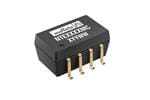
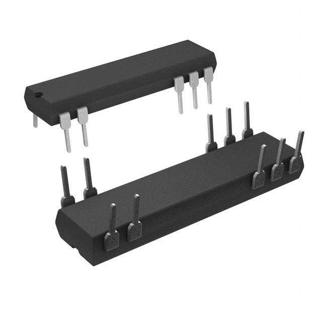
| 描述 | CONV DC/DC 1W 12VIN 15V SGL 1KV隔离式DC/DC转换器 12Vin 15Vout 66mA Isolated 1W SMT |
| 产品分类 | DC DC ConvertersDC/DC转换器 |
| 品牌 | Murata Power Solutions |
| 产品手册 | |
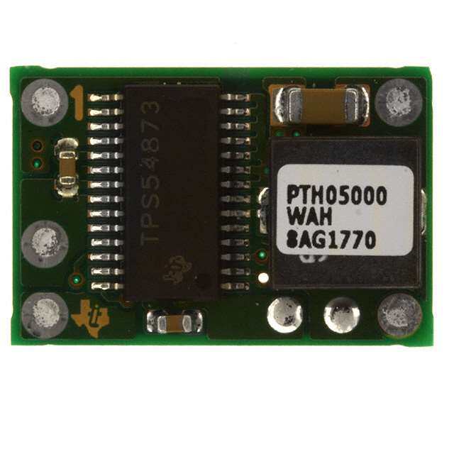
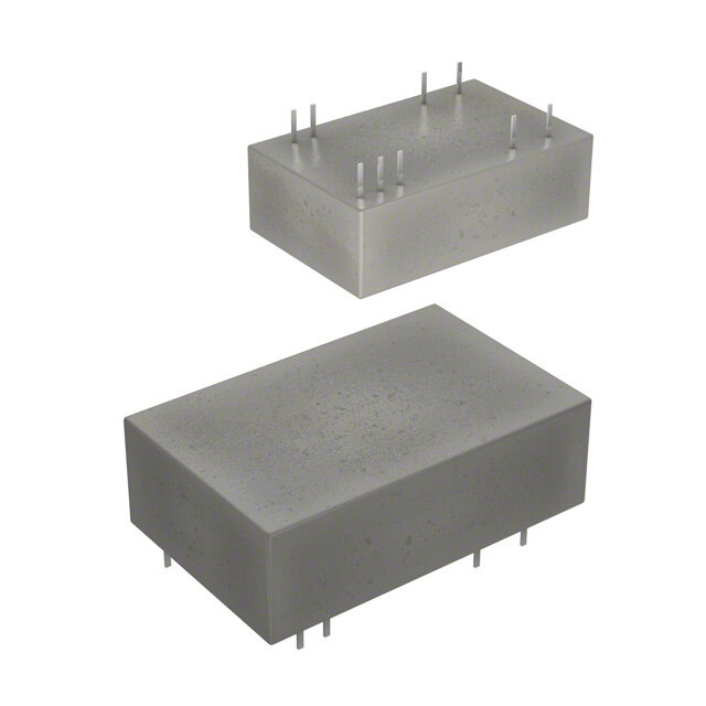
| 产品图片 |
|
| rohs | RoHS 合规性豁免无铅 / 符合限制有害物质指令(RoHS)规范要求 |
| 产品系列 | 隔离式DC/DC转换器,Murata Power Solutions NTE1215MCNTE |
| 数据手册 | |
| 产品型号 | NTE1215MC |
| 产品 | Isolated |
| 产品培训模块 | http://www.digikey.cn/PTM/IndividualPTM.page?site=cn&lang=zhs&ptm=21791 |
| 产品目录页面 | |
| 产品种类 | 隔离式DC/DC转换器 |
| 其它名称 | 811-1688-5 |
| 功率(W)-制造系列 | 1W |
| 功率(W)-最大值 | 1W |
| 包装 | 管件 |
| 商标 | Murata Power Solutions |
| 大小/尺寸 | 0.50" 长 x 0.30" 宽 x 0.26" 高(12.7mm x 7.6mm x 6.6mm) |
| 安装类型 | 表面贴装 |
| 封装 | Tube |
| 封装/外壳 | 14-SMD 模块 (8 引线) |
| 工作温度 | -40°C ~ 85°C |
| 工厂包装数量 | 35 |
| 效率 | 75% |
| 标准包装 | 35 |
| 特性 | - |
| 电压-输入(最大值) | 13.2V |
| 电压-输入(最小值) | 10.8V |
| 电压-输出1 | 15V |
| 电压-输出2 | - |
| 电压-输出3 | - |
| 电压-隔离 | 1kV(1000V) |
| 电流-输出(最大值) | 66mA |
| 类型 | 隔离模块 |
| 系列 | NTE |
| 绝缘电压 | 1 kV |
| 输入电压—公称值 | 12 V |
| 输入电压范围 | 10.8 V to 13.2 V |
| 输出功率 | 1 W |
| 输出数 | 1 |
| 输出电压—通道1 | 15 V |
| 输出电流—通道1 | 66 mA |
| 输出端数量 | 1 |


- 商务部:美国ITC正式对集成电路等产品启动337调查
- 曝三星4nm工艺存在良率问题 高通将骁龙8 Gen1或转产台积电
- 太阳诱电将投资9.5亿元在常州建新厂生产MLCC 预计2023年完工
- 英特尔发布欧洲新工厂建设计划 深化IDM 2.0 战略
- 台积电先进制程称霸业界 有大客户加持明年业绩稳了
- 达到5530亿美元!SIA预计今年全球半导体销售额将创下新高
- 英特尔拟将自动驾驶子公司Mobileye上市 估值或超500亿美元
- 三星加码芯片和SET,合并消费电子和移动部门,撤换高东真等 CEO
- 三星电子宣布重大人事变动 还合并消费电子和移动部门
- 海关总署:前11个月进口集成电路产品价值2.52万亿元 增长14.8%


PDF Datasheet 数据手册内容提取
NTE Series www.murata-ps.com Isolated 1W Single Output SM DC/DC Converters SELECTION GUIDE Nominal Input Output Output Isolation Input Current at Efficiency MTTF2 Order Code1 Voltage Current Capacitance Voltage Rated Load V V mA mA % pF kHrs NTE0303MC 3.3 3.3 303 410 73 30 5348 NTE0305MC 3.3 5 200 390 78 35 3847 NTE0309MC 3.3 9 111 400 77 31 3134 FEATURES NTE0312MC 3.3 12 83 400 77 28 3473 NTE0315MC 3.3 15 66 400 77 29 2473 (cid:132)(cid:3)RoHS compliant NTE0503MC 5 3.3 303 270 74 40 5515 (cid:132)(cid:3)Lead frame technology NTE0505MC 5 5 200 294 68 35 6857 NTE0505MEC 5 5 200 260 77 40 3933 (cid:132)(cid:3)Single isolated output NTE0506MC 5 6 167 278 72 39 6677 (cid:132)(cid:3)1kVDC Isolation NTE0509MC 5 9 111 267 75 43 5501 NTE0512MC 5 12 83 260 77 42 3957 (cid:132)(cid:3)Efficiency up to 78% NTE0515MC 5 15 66 256 78 44 2747 (cid:132)(cid:3)Power density 1.8W/cm3 NTE1205MC 12 5 200 124 67 47 4683 NTE1209MC 12 9 111 114 73 77 4008 (cid:132)(cid:3)Wide temperature performance at full NTE1212MC 12 12 83 113 74 88 3121 1 Watt load, –40°C to 85°C NTE1215MC 12 15 66 111 75 95 2316 (cid:132)(cid:3)UL 94V-0 Package material (cid:132)(cid:3)Footprint over pins 1.37cm2 INPUT CHARACTERISTICS Parameter Conditions Min. Typ. Max. Units (cid:132)(cid:3)3.3V, 5V & 12V Input Continuous operation, 3.3V input types 2.97 3.3 3.63 (cid:132)(cid:3)3.3V, 5V, 9V, 12V & 15V output Voltage range Continuous operation, 5V input types 4.5 5.0 5.5 V Continuous operation, 12V input types 10.8 12.0 13.2 (cid:132)(cid:3)No heatsink required Reflected ripple current 30 47 mA p-p (cid:132)(cid:3)Internal SMD construction ISOLATION CHARACTERISTICS (cid:132)(cid:3)Toroidal magnetics Parameter Conditions Min. Typ. Max. Units (cid:132)(cid:3)MTTF up to 6.8 million hours Isolation voltage Flash tested for 1 second 1000 VDC (cid:132)(cid:3)Custom solutions available Resistance Viso= 1000VDC 10 GΩ (cid:132)(cid:3)Multi-layer ceramic capacitors GENERAL CHARACTERISTICS Parameter Conditions Min. Typ. Max. Units PRODUCT OVERVIEW Switching frequency All output types 110 kHz The NTE series of miniature surface mounted DC/DC Converters employ leadframe technol- ABSOLUTE MAXIMUM RATINGS ogy and transfer moulding techniques to bring Internal power dissipation 600mW all of the benefits of IC style packaging to hybrid Input voltage VIN, NTE03 types 5.5V circuitry. The co-planarity of the pin positions is Input voltage VIN, NTE05 types 7V based upon IEC 191-6:1990. The devices are Input voltage VIN, NTE12 types 15V suitable for all applications where high volume 1. If components are required in tape and reel format suffix order code with -R, e.g. NTE0505MC-R. production is envisaged. 2. Calculated using MIL-HDBK-217 FN2 calculation model with nominal input voltage at full load. All specifications typical at TA=25°C, nominal input voltage and rated output current unless otherwise specified. For full details go to www.murata-ps.com/rohs www.murata-ps.com/support KDC_NTE.K05 Page 1 of 6
NTE Series Isolated 1W Single Output SM DC/DC Converters OUTPUT CHARACTERISTICS Parameter Conditions Min. Typ. Max. Units Rated power TA=-40°C to 85°C 1.0 W Voltage set point accuracy See tolerance envelope Line regulation High VIN to low VIN 1.0 1.2 %/% 10% load to rated load, 03XXMC, 0503MC, 0505MEC 10 14 10% load to rated load, 0505MC & 1205MC 12.8 15 10% load to rated load, 0506MC 9.2 10 Load regulation1 % 10% load to rated load, 0509MC & 1209MC 8.3 9.0 10% load to rated load, 0512MC & 1212MC 6.8 7.5 10% load to rated load, 0515MC & 1215MC 6.3 7.0 BW=DC to 20MHz, 03XXMC, 0503MC, 0505MEC 40 60 BW=DC to 20MHz, 0505MC & 1205MC 62 85 BW=DC to 20MHz, 0506MC 103 170 Ripple and noise mV p-p BW=DC to 20MHz, 0509MC & 1209MC 49 75 BW=DC to 20MHz, 0512MC & 1212MC 39 65 BW=DC to 20MHz, 0515MC & 1215MC 38 76 TEMPERATURE CHARACTERISTICS Parameter Conditions Min. Typ. Max. Units Specification All output types -40 85 Storage -55 125 0305MC, 0309MC, 0315MC 25 °C Case temperature rise above 0303MC, 0312MC, 0503MC, 0505MEC, 0509MC, 0512MC, 0515MC 30 ambient 0505MC, 1205MC 43 1209MC, 1212MC, 1215MC 40 Cooling Free air convection TECHNICAL NOTES ISOLATION VOLTAGE ‘Hi Pot Test’, ‘Flash Tested’, ‘Withstand Voltage’, ‘Proof Voltage’, ‘Dielectric Withstand Voltage’ & ‘Isolation Test Voltage’ are all terms that relate to the same thing, a test voltage, applied for a specified time, across a component designed to provide electrical isolation, to verify the integrity of that isolation. Murata Power Solutions NTE series of DC/DC converters are all 100% production tested at their stated isolation voltage. This is 1kVDC for 1 second. A question commonly asked is, “What is the continuous voltage that can be applied across the part in normal operation?” For a part holding no specific agency approvals, such as the NTE series, both input and output should normally be maintained within SELV limits i.e. less than 42.4V peak, or 60VDC. The isolation test voltage represents a measure of immunity to transient voltages and the part should never be used as an element of a safety isolation system. The part could be expected to function correctly with several hundred volts offset applied continuously across the isolation barrier; but then the circuitry on both sides of the barrier must be regarded as operating at an unsafe voltage and further isolation/insulation systems must form a barrier between these circuits and any user-accessible circuitry according to safety standard requirements. REPEATED HIGH-VOLTAGE ISOLATION TESTING It is well known that repeated high-voltage isolation testing of a barrier component can actually degrade isolation capability, to a lesser or greater degree depending on materials, construction and environment. The NTE series has toroidal isolation transformers, with no additional insulation between primary and secondary windings of enameled wire. While parts can be expected to withstand several times the stated test voltage, the isolation capability does depend on the wire insulation. Any material, including this enamel (typically polyurethane) is susceptible to eventual chemical degradation when subject to very high applied voltages thus implying that the number of tests should be strictly limited. We therefore strongly advise against repeated high voltage isolation testing, but if it is absolutely required, that the voltage be reduced by 20% from specified test voltage. This consideration equally applies to agency recognized parts rated for better than functional isolation where the wire enamel insulation is always supplemented by a further insulation system of physical spacing or barriers. TEMPERATURE DERATING GRAPH 1.5 er (W)1.0 85°C w Po ut 0.5 Safe Operating Area p ut O 0 -40 0 50 100 150 Ambient Temperature (°C) 1. 12V input types have typically 3% less load regulation change. www.murata-ps.com/support KDC_NTE.K05 Page 2 of 6
NTE Series Isolated 1W Single Output SM DC/DC Converters TOLERANCE ENVELOPES 3.3V output types. All other types. +9% +10% +1% Typical Load Line +1% +5% Typical Load Line +2.5% V V NOM NOM -2.5% e e ag -7% -7% ag -7.5% ut Volt -15% ut Volt p p ut ut O 10 25 50 75 100 O 10 25 50 75 100 Output Load Current (%) Output Load Current (%) The voltage tolerance envelope shows typical load regulation characteristics for this product series. The tolerance envelope is the maximum output voltage variation due to changes in output loading. RoHS COMPLIANCE, MSL AND PSL INFORMATION This series is compatible with RoHS soldering systems and is also backward compatible with Sn/Pb soldering systems. The NTE series has a process, moisture, and reflow sensitivity classification of MSL1 PSL R7F as defined in J-STD-020 and J-STD-075. This translates to: MSL1 = unlimited floor life, PSL R7F = Peak reflow temperature 245°C with a limitation on the time above liquidus (217°C) which for this series is 60sec max. The pin termination finish on this product series is Gold with a plating thickness of 0.05 microns minimum. For further information please visit www.murata-ps.com/rohs APPLICATION NOTES Minimum load The minimum load to meet datasheet specification is 10% of the full rated load across the specified input voltage range. Lower than 10% minimum loading will result in an increase in output voltage, which may rise to typically double the specified output voltage if the output load falls to less than 5%. Capacitive loading and start up Typical start up times for this series, with a typical input voltage rise time of 2.2μs and output capacitance of 10μF, are shown in the table below. The product series will start into a capacitance of 47μF with an increased start time, however, the maximum recommended output capacitance is 10μF. Typical Start-Up Wave Form Start-up time Start-up time μs μs NTE0303MC 437 NTE0506MC 7200 NTE0305MC 1359 NTE0509MC 3146 NTE0309MC 3435 NTE0512MC 4960 NTE0312MC 6590 NTE0515MC 7740 NTE0315MC 7625 NTE1205MC 895 NTE0503MC 533 NTE1209MC 2150 NTE0505MC 1368 NTE1212MC 3640 NTE0505MEC 721 NTE1215MC 7180 www.murata-ps.com/support KDC_NTE.K05 Page 3 of 6
NTE Series Isolated 1W Single Output SM DC/DC Converters APPLICATION NOTES (continued) Output Ripple Reduction By using the values of inductance and capacitance stated, the output ripple at the rated load is lowered to 5mV p-p max. Component selection Capacitor: It is required that the ESR (Equivalent Series Resistance) should be as low as possible, ceramic types are recommended. The voltage rating should be at least twice (except for 15V output), the rated output voltage of the DC/DC converter. Inductor: The rated current of the inductor should not be less than that of the output of the DC/DC converter. At the rated current, the DC resistance of the inductor should be such that the voltage drop across the inductor is <2% of the rated voltage of the DC/DC converter. The SRF (Self Resonant Frequency) should be >20MHz. L DC Power C Load Source DC Inductor Capacitor L, μH SMD Through Hole C, μF NTE0303MC 10 82103C 11R103C 4.7 NTE0305MC 47 82473C 11R103C 4.7 NTE0309MC 22 82223C 11R223C 2.2 NTE0312MC 10 82103C 11R103C 1 NTE0315MC 47 82473C 11R473C 1 NTE0503MC 10 82103C 11R103C 4.7 NTE0505MC 47 82473C 11R473C 4.7 NTE0505MEC 47 82473C 11R473C 4.7 NTE0506MC 10 82103C 11R103C 4.7 NTE0509MC 22 82223C 11R223C 2.2 NTE0512MC 47 82473C 11R473C 1 NTE0515MC 47 82473C 11R473C 1 NTE1205MC 47 82473C 11R473C 4.7 NTE1209MC 22 82223C 11R223C 2.2 NTE1212MC 47 82473C 11R473C 1 NTE1215MC 47 82473C 11R473C 1 www.murata-ps.com/support KDC_NTE.K05 Page 4 of 6
NTE Series Isolated 1W Single Output SM DC/DC Converters PACKAGE SPECIFICATIONS MECHANICAL DIMENSIONS PIN CONNECTIONS 12.7 [0.500] DETAIL A 7.62 [0.300] Pin Function 14 8 RPLEAFNEREENCE 0.50 [0.020] 1 -VIN [ ] P 3 +VIN 1110..2400 00..444019 7.70 [0.303] NTE0505MC 5 NA 1K1533 7 1.5x08 [ 0P.I0N5S9] ±5.0° 7 -VOUT 1.20 [0.047] 8 +VOUT 2.54 [0.100] 0.2 [0.008] S 10 NA 12 NA x8 [PINS ] 0.2 [0.008] S 00..7455 00..003108 14 NA (1.875 [0.074] MAX) 2.79 [0.110] MAX NA - Not available for electrical connection. [ ] [ ] 2.10 [0.083] 6.60 0.260 (6.35) (0.250) [ ] (5.95) (0.234) 5.85 0.230 S 0.30 0.012 0.20 0.008 [ ] SEATING PLANE 0.25 0.010 x8 PINS 0.10 0.004 DETAIL A 0.10 [0.004] S All dimensions in mm ±0.25mm (inches ±0.01). All pins on a 2.54 (0.1) pitch and within ± 0.25 (0.01) of true position. Weight: 1.21g RECOMMENDED FOOTPRINT DETAILS TUBE OUTLINE DIMENSIONS 7.62 [0.300] 0.60±0.15 (0.024±0.006) 2.10 (0.083) x8 PLACES 2.30 [0.091] 9.40 [0.370] 14.35 (0.565) 9.40 (0.370) x8 PLACES 1.00 [0.039] 2.54 [0.100] 6.70 (0.264) All pins on a 2.54mm pitch. Unless otherwise stated all dimensions in mm±0.5mm (inches ±0.02). Unless otherwise stated all dimensions in mm (inches) ±0.5mm. Tube length : 475±2.0 (18.70±0.07). Tube Quantity : 35 www.murata-ps.com/support KDC_NTE.K05 Page 5 of 6
NTE Series Isolated 1W Single Output SM DC/DC Converters TAPE & REEL SPECIFICATIONS REEL OUTLINE DIMENSIONS TAPE OUTLINE DIMENSIONS 330 (12.99) MAX 13.20 (0.52) 0.60 (0.02) MAX 100 Ø (3.94) MIN +0.004 (+0.10) 1.50 (Ø0.06) -0.00 (-0.00) G N 2.00(+0.08)(AT HUB SECTION)24.40 (0.96)-0.00 (0.00) Ø 1(03..5010±±00..02059) 30.40 (1.20) MAX ((0240....00010806) ) (101.DIRECTION OF UNREELI.4660) 16.00 (0.63) 1.75(0.07) 6.60 11.50 (0.26) (0.45) 24.00±0.30 (0.94±0.04) REEL PACKAGING DETAILS XYYWWNTE0505MC XYYWWNTE0505MC XYYWWNTE0505MC TRAILER SECTION GOODS ENCLOSURE CARRIER TAPE START 160 (6.30) MIN SECTION 100 (3.94) MIN Product Orientation Pin 1, located nearest to LEADER SECTION carrier drive sprocket. 400 (15.75) MIN Reel Quantity : 500 This product is subject to the following operating requirements Murata Power Solutions, Inc. and the Life and Safety Critical Application Sales Policy: 11 Cabot Boulevard, Mansfield, MA 02048-1151 U.S.A. Refer to: http://www.murata-ps.com/requirements/ ISO 9001 and 14001 REGISTERED Murata Power Solutions, Inc. makes no representation that the use of its products in the circuits described herein, or the use of other technical information contained herein, will not infringe upon existing or future patent rights. The descriptions contained herein do not imply the granting of licenses to make, use, or sell equipment constructed in accordance therewith. Specifications are subject to change without notice. © 2015 Murata Power Solutions, Inc. www.murata-ps.com/support KDC_NTE.K05 Page 6 of 6
Mouser Electronics Authorized Distributor Click to View Pricing, Inventory, Delivery & Lifecycle Information: M urata: NTE0303M NTE0305M NTE0503M NTE0505M NTE0512M NTE0515M NTE1205M NTE1212M NTE1215M NTE0509M NTE1209M NTE0505ME NTE1205MC NTE0505MC NTE0515MC NTE1215MC NTE0303MC-R NTE0305MC-R NTE0309MC NTE0309MC-R NTE0312MC NTE0312MC-R NTE0315MC NTE0315MC-R NTE0503MC-R NTE0505MC-R NTE0505MEC NTE0505MEC-R NTE0509MC-R NTE0512MC-R NTE0515MC-R NTE1205MC-R NTE1209MC NTE1209MC-R NTE1212MC-R NTE1215MC-R NTE0506MC NTE0512MC NTE1212MC NTE0303MC NTE0305MC NTE0503MC NTE0509MC NTE0506MC-R