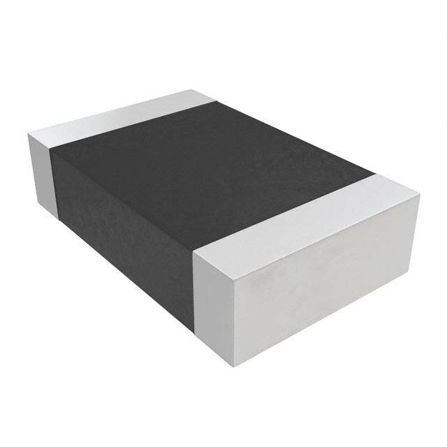
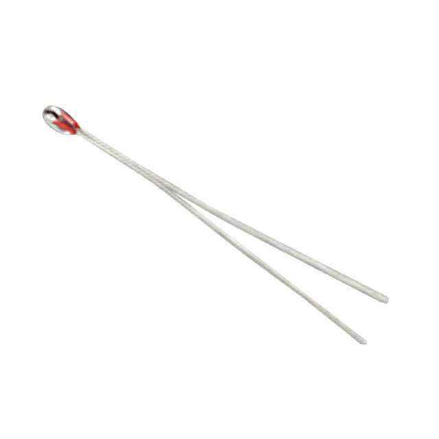
ICGOO在线商城 > 传感器,变送器 > 温度传感器 - NTC 热敏电阻器 > NTCSMELFE3104JT
- 型号: NTCSMELFE3104JT
- 制造商: Vishay
- 库位|库存: xxxx|xxxx
- 要求:
| 数量阶梯 | 香港交货 | 国内含税 |
| +xxxx | $xxxx | ¥xxxx |
查看当月历史价格
查看今年历史价格
NTCSMELFE3104JT产品简介:
ICGOO电子元器件商城为您提供NTCSMELFE3104JT由Vishay设计生产,在icgoo商城现货销售,并且可以通过原厂、代理商等渠道进行代购。 NTCSMELFE3104JT价格参考¥2.37-¥2.54。VishayNTCSMELFE3104JT封装/规格:温度传感器 - NTC 热敏电阻器, NTC Thermistor 100k DO-213AC, MINI-MELF, SOD-80。您可以下载NTCSMELFE3104JT参考资料、Datasheet数据手册功能说明书,资料中有NTCSMELFE3104JT 详细功能的应用电路图电压和使用方法及教程。
| 参数 | 数值 |
| 25°C时欧姆阻值 | 100k |
| B0/50 | - |
| B25/100 | - |
| B25/50 | - |
| B25/75 | - |
| B25/85 | 3997K |
| B值容差 | ±1.3% |
| 产品目录 | |
| 描述 | THERMISTOR NTC 100K 5% MELF热敏电阻 - NTC 100Kohms 5% |
| 产品分类 | 热敏电阻 - NTC热敏电阻 - NTC |
| 品牌 | Vishay BC ComponentsVishay / BC Components |
| 产品手册 | |
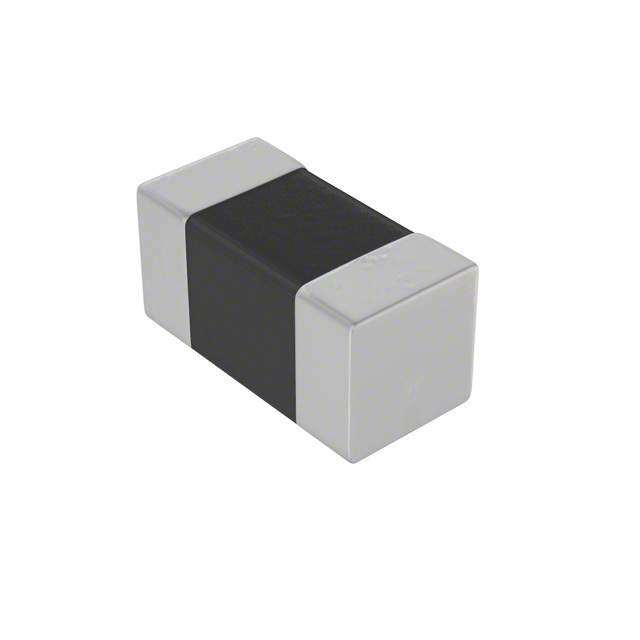
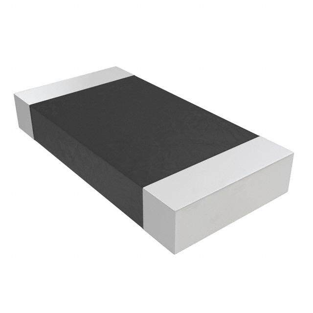
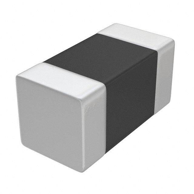
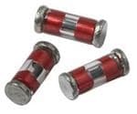
| 产品图片 |
|
| rohs | RoHS 合规性豁免无铅 / 符合限制有害物质指令(RoHS)规范要求 |
| 产品系列 | Vishay / BC Components NTCSMELFE3104JT2381 |
| 数据手册 | http://www.vishay.com/doc?29119 |
| 产品型号 | NTCSMELFE3104JTNTCSMELFE3104JT |
| 产品培训模块 | http://www.digikey.cn/PTM/IndividualPTM.page?site=cn&lang=zhs&ptm=30307 |
| 产品种类 | 热敏电阻 - NTC |
| 其它名称 | BC2545DKR |
| 功率-最大值 | 100mW |
| 功率额定值 | 100 mW |
| 包装 | Digi-Reel® |
| 商标 | Vishay / BC Components |
| 安装类型 | 表面贴装 |
| 容差 | 5 % |
| 封装 | Reel |
| 封装/外壳 | SOD-80 |
| 封装/箱体 | MELF |
| 尺寸 | 1.55 mm Dia. x 3.5 mm L |
| 工作温度 | -40°C ~ 150°C |
| 工作温度范围 | - 40 C to + 150 C |
| 工厂包装数量 | 2500 |
| 标准包装 | 1 |
| 特色产品 | http://www.digikey.cn/product-highlights/zh/ntcs-series-thermistors/52838 |
| 电阻 | 100 kOhms |
| 电阻容差 | ±5% |
| 端接类型 | Melf |
| 类型 | NTC |
| 系列 | NTCSxxxxE3..T |
| 长度-引线 | - |
| 零件号别名 | 2381-633-53104 |


- 商务部:美国ITC正式对集成电路等产品启动337调查
- 曝三星4nm工艺存在良率问题 高通将骁龙8 Gen1或转产台积电
- 太阳诱电将投资9.5亿元在常州建新厂生产MLCC 预计2023年完工
- 英特尔发布欧洲新工厂建设计划 深化IDM 2.0 战略
- 台积电先进制程称霸业界 有大客户加持明年业绩稳了
- 达到5530亿美元!SIA预计今年全球半导体销售额将创下新高
- 英特尔拟将自动驾驶子公司Mobileye上市 估值或超500亿美元
- 三星加码芯片和SET,合并消费电子和移动部门,撤换高东真等 CEO
- 三星电子宣布重大人事变动 还合并消费电子和移动部门
- 海关总署:前11个月进口集成电路产品价值2.52万亿元 增长14.8%

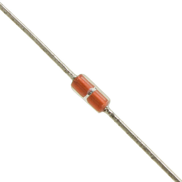
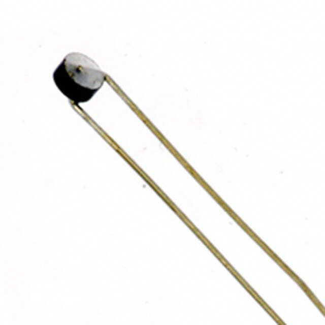
PDF Datasheet 数据手册内容提取
NTCSMELFE3 www.vishay.com Vishay BCcomponents SMD MELF SOD80, Glass Encapsulated NTC Thermistors FEATURES • Small diameter down to 1.7 mm • Quick response time down to 0.9 s • Resistant to corrosive atmospheres and harsh environments • Wide temperature range from -40 °C to +150 °C • Available on tape • Material categorization: for definitions of compliance please see www.vishay.com/doc?99912 QUICK REFERENCE DATA APPLICATIONS PARAMETER VALUE UNIT Temperature measurement, sensing and control: Resistance value at 25 °C 10K to 100K • Domestic appliances Tolerance on R25-value ± 5 % • Industrial process control B -value 3977 K 25/85 DESCRIPTION Tolerance on B -value ± 1.3 % 25/85 These thermistors consist of a micro chip clamped between Operating temperature range -40 to +150 °C Dumet electrodes in a glass sealing with tin plated Maximum power dissipation 100 mW terminations. Only available in tape and reel packaging. at 55 °C Dissipation factor 2.5 mW/K DESIGN-IN SUPPORT Response time 0.9 s For complete curve computation, please visit: www.vishay.com/thermistors/ntc-curve-list/ Thermal time constant 6 s Weight 0.03 g MOUNTING By soldering. Not intended for potting or automotive applications. ELECTRICAL DATA AND ORDERING INFORMATION R R -TOL. B B -TOL. SAP MATERIAL AND 25 25 25/85 25/85 () (± %) (K) (± %) ORDERING NUMBER 10 000 5 3 977 1.3 NTCSMELFE3103JT 20 000 5 3 977 1.3 NTCSMELFE3203JT 30 000 5 3 977 1.3 NTCSMELFE3303JT 100 000 5 3 977 1.3 NTCSMELFE3104JT DIMENSIONS in millimeters ØD D L L 2 2 L 1 L L ØD 1 2 3.5 ± 0.35 0.35 ± 0.1 1.55 ± 0.15 Revision: 24-Aug-17 1 Document Number: 29119 For technical questions, contact: nlr@vishay.com THIS DOCUMENT IS SUBJECT TO CHANGE WITHOUT NOTICE. THE PRODUCTS DESCRIBED HEREIN AND THIS DOCUMENT ARE SUBJECT TO SPECIFIC DISCLAIMERS, SET FORTH AT www.vishay.com/doc?91000
NTCSMELFE3 www.vishay.com Vishay BCcomponents PACKAGING BLISTER TAPE ON REEL Packed in an 8 mm wide blister tape on a 180 mm reel, according to IEC 60286-3 K0 D0 P0 T P2 E F W B0 B0 T2 A D1 0 P DIMENSIONS in millimeters PARAMETER VALUE A 2.1 + 0.3 / - 0.0 0 B min. 3.8 0 K 2.1 + 0.3 / - 0.0 0 W 8 ± 0.2 F 3.5 ± 0.1 E 1.75 ± 0.1 P 4.0 ± 0.1 P 4.0 ± 0.1 0 P 2.0 ± 0.05 2 D 1.5 ± 0.1 0 D 1.0 ± 0.1 1 T max. 0.4 T max. 0.5 2 STABILITY CHARACTERISTICS Stability of glass encapsulated NTCs in thermal shock test (200 000 cycles -40 °C / +200 °C). Tested on non-soldered parts. 0.8 0 R T R (K) (%) T (at 25 °C) 0.6 - 0.1 T (at 85 °C) R /R 85 85 0.4 - 0.2 R /R 25 25 0.2 - 0.3 0 - 0.4 103 104 105 Cycles 106 Revision: 24-Aug-17 2 Document Number: 29119 For technical questions, contact: nlr@vishay.com THIS DOCUMENT IS SUBJECT TO CHANGE WITHOUT NOTICE. THE PRODUCTS DESCRIBED HEREIN AND THIS DOCUMENT ARE SUBJECT TO SPECIFIC DISCLAIMERS, SET FORTH AT www.vishay.com/doc?91000
NTCSMELFE3 www.vishay.com Vishay BCcomponents DERATING Power derating curve P (%) 100 0 -40 0 55 85 150 T (°C) amb Note • Zero power is considered as measuring power max. 1 % of max. power For complete curve computation, visit: www.vishay.com/thermistors/ntc-curve-list/. RESISTANCE VALUES AT INTERMEDIATE TEMPERATURES FOR NTCSMELFE3 TEMPERATURE R-TOL. T-TOL. (°C) RT/R25 R for 10 k R for 20 k R for 30 k R for 100 k (± %) (%/K) (± °C) -40 33.21 332 094 664 187 996 281 3 320 936 10.08 -6.62 1.52 -35 23.99 239 900 479 799 719 699 2 398 996 9.59 -6.39 1.50 -30 17.52 175 200 350 399 525 599 1 751 996 9.12 -6.18 1.48 -25 12.93 129 287 258 574 387 861 1 292 869 8.67 -5.98 1.45 -20 9.636 96 358 192 716 289 074 963 582 8.24 -5.78 1.42 -15 7.250 72 500 145 001 217 501 725 004 7.82 -5.60 1.40 -10 5.505 55 046 110 092 165 138 550 459 7.42 -5.42 1.37 -5 4.216 42 157 84 314 126 471 421 570 7.04 -5.25 1.34 0 3.255 32 554 65 108 97 663 325 542 6.67 -5.09 1.31 5 2.534 25 339 50 677 76 016 253 386 6.31 -4.93 1.28 10 1.987 19 872 39 744 59 617 198 722 5.96 -4.79 1.25 15 1.570 15 698 31 397 47 095 156 985 5.63 -4.64 1.21 20 1.249 12 488 24 975 37 463 124 877 5.31 -4.51 1.18 25 1.000 10 000 20 000 30 000 100 000 5.00 -4.38 1.14 30 0.8059 8059 16118 24 177 80 591 5.30 -4.25 1.25 35 0.6535 6535 13069 19 604 65 347 5.59 -4.13 1.35 40 0.5330 5330 10660 15 990 53 299 5.87 -4.02 1.46 45 0.4372 4372 8743 13 115 43 717 6.14 -3.91 1.57 50 0.3605 3605 7211 10 816 36 053 6.41 -3.80 1.69 55 0.2989 2989 5977 8966 29887 6.66 -3.70 1.80 60 0.2490 2490 4980 7470 24900 6.91 -3.60 1.92 65 0.2084 2084 4169 6253 20844 7.15 -3.51 2.04 70 0.1753 1753 3506 5259 17530 7.39 -3.42 2.16 75 0.1481 1481 2962 4443 14809 7.61 -3.33 2.29 80 0.1256 1256 2513 3769 12564 7.84 -3.25 2.41 85 0.1070 1070 2141 3211 10703 8.05 -3.17 2.54 90 0.09154 915.4 1831 2746 9154 8.26 -3.09 2.67 95 0.07860 786.0 1572 2358 7860 8.46 -3.01 2.81 100 0.06773 677.3 1355 2032 6773 8.66 -2.94 2.95 105 0.05857 585.7 1171 1757 5857 8.85 -2.87 3.08 110 0.05083 508.3 1017 1525 5083 9.04 -2.80 3.23 115 0.04426 442.6 885.2 1328 4426 9.22 -2.74 3.37 120 0.03866 386.6 773.2 1160 3866 9.40 -2.67 3.52 125 0.03387 338.7 677.5 1016 3387 9.57 -2.61 3.66 130 0.02977 297.7 595.4 893.1 2977 9.74 -2.55 3.81 135 0.02624 262.4 524.8 787.2 2624 9.91 -2.50 3.97 140 0.02319 231.9 463.8 695.7 2319 10.07 -2.44 4.12 145 0.02055 205.5 411.1 616.6 2055 10.23 -2.39 4.28 150 0.01826 182.6 365.3 547.9 1826 10.38 -2.34 4.44 Revision: 24-Aug-17 3 Document Number: 29119 For technical questions, contact: nlr@vishay.com THIS DOCUMENT IS SUBJECT TO CHANGE WITHOUT NOTICE. THE PRODUCTS DESCRIBED HEREIN AND THIS DOCUMENT ARE SUBJECT TO SPECIFIC DISCLAIMERS, SET FORTH AT www.vishay.com/doc?91000
Legal Disclaimer Notice www.vishay.com Vishay Disclaimer ALL PRODUCT, PRODUCT SPECIFICATIONS AND DATA ARE SUBJECT TO CHANGE WITHOUT NOTICE TO IMPROVE RELIABILITY, FUNCTION OR DESIGN OR OTHERWISE. Vishay Intertechnology, Inc., its affiliates, agents, and employees, and all persons acting on its or their behalf (collectively, “Vishay”), disclaim any and all liability for any errors, inaccuracies or incompleteness contained in any datasheet or in any other disclosure relating to any product. Vishay makes no warranty, representation or guarantee regarding the suitability of the products for any particular purpose or the continuing production of any product. To the maximum extent permitted by applicable law, Vishay disclaims (i) any and all liability arising out of the application or use of any product, (ii) any and all liability, including without limitation special, consequential or incidental damages, and (iii) any and all implied warranties, including warranties of fitness for particular purpose, non-infringement and merchantability. Statements regarding the suitability of products for certain types of applications are based on Vishay’s knowledge of typical requirements that are often placed on Vishay products in generic applications. Such statements are not binding statements about the suitability of products for a particular application. It is the customer’s responsibility to validate that a particular product with the properties described in the product specification is suitable for use in a particular application. Parameters provided in datasheets and / or specifications may vary in different applications and performance may vary over time. All operating parameters, including typical parameters, must be validated for each customer application by the customer’s technical experts. Product specifications do not expand or otherwise modify Vishay’s terms and conditions of purchase, including but not limited to the warranty expressed therein. Except as expressly indicated in writing, Vishay products are not designed for use in medical, life-saving, or life-sustaining applications or for any other application in which the failure of the Vishay product could result in personal injury or death. Customers using or selling Vishay products not expressly indicated for use in such applications do so at their own risk. Please contact authorized Vishay personnel to obtain written terms and conditions regarding products designed for such applications. No license, express or implied, by estoppel or otherwise, to any intellectual property rights is granted by this document or by any conduct of Vishay. Product names and markings noted herein may be trademarks of their respective owners. © 2017 VISHAY INTERTECHNOLOGY, INC. ALL RIGHTS RESERVED Revision: 08-Feb-17 1 Document Number: 91000
Mouser Electronics Authorized Distributor Click to View Pricing, Inventory, Delivery & Lifecycle Information: V ishay: NTCSMELFE3103JT NTCSMELFXX103JT 2381-633-53104 NTCSMELFE3104JT NTCSMELFE3203JT NTCSMELFE3303JT
 Datasheet下载

