
 Datasheet下载
- 型号: NPH10S2412EIC
- 制造商: Murata
- 库位|库存: xxxx|xxxx
- 要求:
| 数量阶梯 | 香港交货 | 国内含税 |
| +xxxx | $xxxx | ¥xxxx |
查看当月历史价格
查看今年历史价格
NPH10S2412EIC产品简介:
ICGOO电子元器件商城为您提供NPH10S2412EIC由Murata设计生产,在icgoo商城现货销售,并且可以通过原厂、代理商等渠道进行代购。 NPH10S2412EIC价格参考。MurataNPH10S2412EIC封装/规格:直流转换器, 隔离模块 DC/DC 转换器 1 输出 12.1V 830mA 18V - 36V 输入。您可以下载NPH10S2412EIC参考资料、Datasheet数据手册功能说明书,资料中有NPH10S2412EIC 详细功能的应用电路图电压和使用方法及教程。
| 参数 | 数值 |
| 产品目录 | |
| 描述 | CONV DC/DC 10W24VIN 12.1VOUT DIP隔离式DC/DC转换器 24Vin 12.1Vout 0.83A Isolated 10W |
| 产品分类 | DC DC ConvertersDC/DC转换器 |
| 品牌 | Murata Power Solutions |
| 产品手册 | |
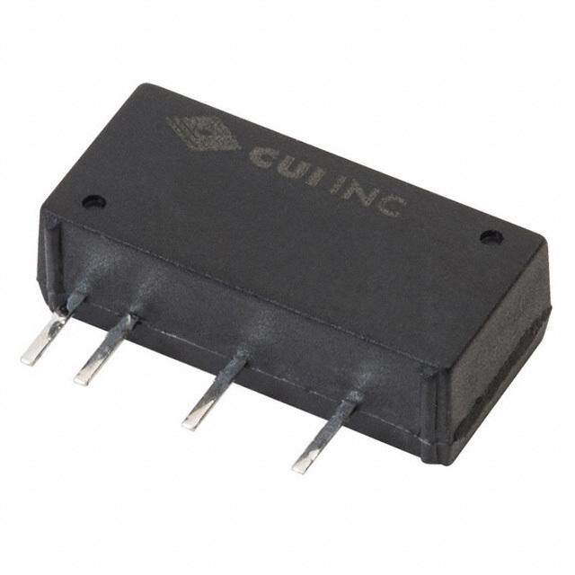
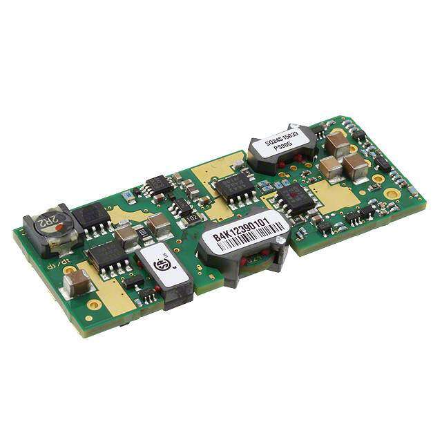
| 产品图片 |
|
| rohs | RoHS 合规性豁免无铅 / 符合限制有害物质指令(RoHS)规范要求 |
| 产品系列 | 隔离式DC/DC转换器,Murata Power Solutions NPH10S2412EICNPH10S |
| 数据手册 | |
| 产品型号 | NPH10S2412EIC |
| 产品 | Isolated |
| 产品培训模块 | http://www.digikey.cn/PTM/IndividualPTM.page?site=cn&lang=zhs&ptm=21792 |
| 产品目录页面 | |
| 产品种类 | 隔离式DC/DC转换器 |
| 其它名称 | 811-1627-5 |
| 功率(W)-制造系列 | 10W |
| 功率(W)-最大值 | 10W |
| 包装 | 管件 |
| 商标 | Murata Power Solutions |
| 大小/尺寸 | 1.26" 长 x 0.98" 宽 x 0.39" 高(32.0mm x 24.9mm x 9.9mm) |
| 安装类型 | 通孔 |
| 安装风格 | Through Hole |
| 宽度 | 1.26 in |
| 封装 | Tube |
| 封装/外壳 | 6-DIP 模块 |
| 封装/箱体尺寸 | DIP |
| 尺寸 | 0.98 in x 1.26 in x 0.39 in |
| 工作温度 | -40°C ~ 110°C |
| 工厂包装数量 | 15 |
| 效率 | 86% |
| 标准包装 | 15 |
| 特性 | - |
| 电压-输入(最大值) | 36V |
| 电压-输入(最小值) | 18V |
| 电压-输出1 | 12.1V |
| 电压-输出2 | - |
| 电压-输出3 | - |
| 电压-隔离 | 1.5kV(1500V) |
| 电流-输出(最大值) | 830mA |
| 类型 | 隔离模块 |
| 系列 | NPH10S |
| 绝缘电压 | 1.5 kV |
| 输入电压—公称值 | 24 V |
| 输入电压范围 | 18 V to 36 V |
| 输出功率 | 10 W |
| 输出数 | 1 |
| 输出电压—通道1 | 12.1 V |
| 输出电流—通道1 | 0.83 A |
| 输出端数量 | 1 |
| 长度 | 0.98 in |
| 高度 | 0.39 in |


- 商务部:美国ITC正式对集成电路等产品启动337调查
- 曝三星4nm工艺存在良率问题 高通将骁龙8 Gen1或转产台积电
- 太阳诱电将投资9.5亿元在常州建新厂生产MLCC 预计2023年完工
- 英特尔发布欧洲新工厂建设计划 深化IDM 2.0 战略
- 台积电先进制程称霸业界 有大客户加持明年业绩稳了
- 达到5530亿美元!SIA预计今年全球半导体销售额将创下新高
- 英特尔拟将自动驾驶子公司Mobileye上市 估值或超500亿美元
- 三星加码芯片和SET,合并消费电子和移动部门,撤换高东真等 CEO
- 三星电子宣布重大人事变动 还合并消费电子和移动部门
- 海关总署:前11个月进口集成电路产品价值2.52万亿元 增长14.8%


PDF Datasheet 数据手册内容提取
NPH10S Series www.murata-ps.com Isolated 10W Single Output DC-DC Converters SELECTION GUIDE Order Code1 Nominal Input Voltage Output Voltage Output Current LimCiut r2r e(Tnytp .) Efficiency Max. LoadCapaci-tance MTTF 3 V V A A % μF kHrs NPH10S2403EiC 24 3.4 2.94 4.3 79 470 279 FEATURES NPH10S2403iC 24 3.4 2.94 4.3 79 470 279 NPH10S2405EiC 24 5.1 1.96 3.1 83 470 275 (cid:132)(cid:3)RoHS compliant NPH10S2405iC 24 5.1 1.96 3.1 83 470 275 (cid:132)(cid:3)High efficiency to 87% NPH10S2412EiC 24 12.1 0.83 1.2 86 100 259 NPH10S2412iC 24 12.1 0.83 1.2 86 100 259 (cid:132)(cid:3)Power density up to 1.5Wcm3 NPH10S2415EiC 24 15.1 0.67 1.1 86 47 243 (cid:132)(cid:3)UL1950 recognized NPH10S2415iC 24 15.1 0.67 1.1 86 47 243 (cid:132)(cid:3)Industry standard pinout NPH10S4803EiC 48 3.4 2.94 4.1 80 470 317 NPH10S4803iC 48 3.4 2.94 4.1 80 470 317 (cid:132)(cid:3)Surge rating to 12W NPH10S4805EiC 48 5.1 1.96 2.8 83 470 312 (cid:132)(cid:3)Non latching current limit NPH10S4805iC 48 5.1 1.96 2.8 83 470 312 Recommended (cid:132)(cid:3)1.5kV input to output isolation Alternative (cid:132)(cid:3)Versatile control options NPH10S4812EiC 48 12.1 0.83 1.3 86 56 291 UEI15-120-Q48P-C NPH10S4812iC 48 12.1 0.83 1.3 86 56 291 UEI15-120-Q48P-C (cid:132)(cid:3)Continuous rating to 10W at 72ºC without NPH10S4815EiC 48 15.1 0.67 1.0 87 22 272 UEI15-150-Q48P-C heatsink NPH10S4815iC 48 15.1 0.67 1.0 87 22 272 UEI15-150-Q48P-C (cid:132)(cid:3)Operation to zero load INPUT CHARACTERISTICS (cid:132)(cid:3)Protected against load faults Parameter Conditions Min. Typ. Max. Units (cid:132)(cid:3)Internal over temperature protection Continuous operation, 24V input types 18 24 36 Voltage range V Continuous operation, 48V input types4 36 48 75 (cid:132)(cid:3)Uses no electrolytic capacitors (cid:132)(cid:3)Fixed frequency OUTPUT CHARACTERISTICS (cid:132)(cid:3)No external components required Parameter Conditions Min. Typ. Max. Units Voltage set point error 50% load after 30 mins at nominal sup- 0.5 % ply voltage DESCRIPTION Case temperature -40ºC to 110ºC The NPH10S series of DC-DC converters combines Overall voltage error Load 0% - 100% 1 2.5 % ease of application with versatility. The pin pattern Input specified range is based on the popular industry standard, but two Temperature coefficient of Over any 10ºC span within the specified additional pins may optionally be fitted to provide 50 250 ppmºC output voltage (slope) temperature range a variety of features not commonly found on units Deviation of output voltage Specified over temperature MIN-MAX 0.5 1 % of this type. High efficiency enables full rating to Line regulation Operating voltage range, 50% load 0.05 0.1 % be achieved in a small package without heat- Load Regulation 0% - 100% rated load5 0.5 % sinking. Thermally protected against sustained Ripple rms 70 mV overload. The copper case achieves efficient heat transfer and screening. The product range has ABSOLUTE MAXIMUM RATINGS been recognised by Underwriters Laboratory (UL) Input voltage, 24V input types -0.5V to 40V 6 to UL 1950 for operational insulation, file number E151252 applies. Input voltage, 48V input types -0.5V to 80V 6 Output voltage -0.3V to controlled output voltage (operating or non-operating) Output trim control -1V to +30V Synchronisation/shutdown control ±15V relative to input return 1. Parts ending with EiC have optional TRIM and SS pins fitted. 2. Current is quoted when output is 95% of regulated voltage. 3. Calculated using MIL-HDBK-217F with nominal input voltage at full load. 4. For applications requiring UL 1950 recognition, input voltage must not exceed 60VDC. 5. A minimum load of 10% of rating is recommended for typical applications. For full details go to 6. Absolute maximum value for 30 seconds. Prolonged application may damage the product. www.murata-ps.com/rohs All specifications typical at TA=25°C, nominal input voltage and rated output current unless otherwise specified. www.murata-ps.com/support KDC_NPH10SC.J05 Page 1 of 8
NPH10S Series Isolated 10W Single Output DC-DC Converters CONTROL CHARACTERISTICS Parameter Conditions Min. Typ. Max. Units Voltage trimming range1 At rated load, trim control at either output ±10 % Remote switch input (voltage relative to For shutdown -15 0 1.5 V input negative)1 Operating, open circuit voltage 9 10 11 Time from application of valid input voltage to output being in specifi- Start delay 25 ms cation Synchronisation1 Specified drive signal 320 440 kHz Switching frequency 330 350 395 kHz ISOLATION CHARACTERISTICS Parameter Conditions Min. Typ. Max. Units Isolation test voltage Flash tested for 1 second 1500 VDC Resistance VISO = 500VDC 1 GΩ 3.3V and 5V output 50 Capacitance pF 12V and 15V output 90 TEMPERATURE CHARACTERISTICS Parameter Conditions Min. Typ. Max. Units Case temperature Full load -40 110 ºC Storage Absolute Max. internal temperature -40 125 Relative humidity Non condensing 85ºC 85 % Thermal protection Operates at case temperature 110 ºC THERMAL CHARACTERISTICS Max. power rating with case temperature maintained by external means (e.g. forced air cooling). Case Temperature Part Number Units 100ºC 105ºC 110ºC NPH20S2403XXX 10 7.0 2.3 NPH10S2405XXX 10 8.2 3.0 W NPH10S2412XXX 10 9.5 4.0 NPH10S2415XXX 12 9.5 4.0 NPH10S4803XXX 10 7.0 1.0 NPH10S4805XXX 10 4.7 1.0 W NPH10S4812XXX 12 8.0 0 NPH10S4815XXX 12 7.5 0 THERMAL PERFORMANCE 24V Input 48V Input (cid:18)(cid:22) (cid:18)(cid:22) (cid:19)(cid:21)(cid:18)(cid:22) (cid:19)(cid:21)(cid:17)(cid:22) (cid:18)(cid:17) (cid:18)(cid:17) (cid:56)(cid:10) (cid:56)(cid:10) (cid:21)(cid:25)(cid:18)(cid:22) (cid:88)(cid:70)(cid:83)(cid:1)(cid:9) (cid:19)(cid:21)(cid:18)(cid:19) (cid:88)(cid:70)(cid:83)(cid:1)(cid:9) (cid:21)(cid:25)(cid:17)(cid:22) (cid:48)(cid:86)(cid:85)(cid:81)(cid:86)(cid:85)(cid:1)(cid:49)(cid:80) (cid:22) (cid:19)(cid:21)(cid:17)(cid:20) (cid:48)(cid:86)(cid:85)(cid:81)(cid:86)(cid:85)(cid:1)(cid:49)(cid:80) (cid:22) (cid:21)(cid:25)(cid:17)(cid:20) (cid:21)(cid:25)(cid:18)(cid:19) (cid:17) (cid:17) (cid:14)(cid:21)(cid:17) (cid:14)(cid:19)(cid:17) (cid:17) (cid:19)(cid:17) (cid:21)(cid:17) (cid:23)(cid:17) (cid:25)(cid:17) (cid:18)(cid:17)(cid:17) (cid:18)(cid:19)(cid:17) (cid:14)(cid:21)(cid:17) (cid:14)(cid:19)(cid:17) (cid:17) (cid:19)(cid:17) (cid:21)(cid:17) (cid:23)(cid:17) (cid:25)(cid:17) (cid:18)(cid:17)(cid:17) (cid:18)(cid:19)(cid:17) (cid:34)(cid:78)(cid:67)(cid:74)(cid:70)(cid:79)(cid:85)(cid:1)(cid:53)(cid:70)(cid:78)(cid:81)(cid:70)(cid:83)(cid:66)(cid:85)(cid:86)(cid:83)(cid:70)(cid:1)(cid:9)(cid:161)(cid:36)(cid:10) (cid:34)(cid:78)(cid:67)(cid:74)(cid:70)(cid:79)(cid:85)(cid:1)(cid:53)(cid:70)(cid:78)(cid:81)(cid:70)(cid:83)(cid:66)(cid:85)(cid:86)(cid:83)(cid:70)(cid:1)(cid:9)(cid:161)(cid:36)(cid:10) 1. Optional - where fitted. www.murata-ps.com/support KDC_NPH10SC.J05 Page 2 of 8
NPH10S Series Isolated 10W Single Output DC-DC Converters APPLICATION NOTES OUTPUT VOLTAGE ADJUSTMENT The trim resistor equations are: VNOM 3.4 5.1 12.1 15.1 Rup = (R/Vup) - S kΩ S 22.2973 20.59761 28.79096 39.95902 Rdown = (L x T ) - T - S kΩ T 10.1351 9.36255 15.42373 20.77869 Vdown R 17.9994 24.49487 94.9661 147.7314 L -1.6241 -2.48374 -5.942857 -7.990244 TRIM UP TRIM DOWN +VIN +VOUT +VIN +VOUT TRIM RDOWN NPH10S NPH10S RUP TRIM -VOUT -VOUT When the output voltage is trimmed up, output current must be derated so that the maximum output power 10W is not exceeded. ( ) Example to decrease output voltage of NPH10S4805EiC by 0.1V: RDOWN = -2.48374 x 9.36255 - 9.36255 - 20.59761 = 203.18kΩ -0.1 SET VOLTAGE The output voltage of all units is set to 100mV above nominal, to offset resistive losses and thus assist with worst case error calculations. For the EiC versions, this allowance can be altered with a single fixed resistor, connected from the trimming pin to one of the output pins. SHUTDOWN FREQUENCY CONTROL When the shutdown pin (SS) is shorted to the negative input, the converter will If the primary side dc control voltage is pulled away from its open circuit stop. Its current consumption will then be less than 1mA at nominal supply volt- voltage, the converter frequency will be changed, approximately in proportion age. The voltage must be less than 1.5V to ensure that the unit stops, and must to the voltage. With +8.5VDC voltage to SS pin, the typical switching frequency be able to sink at least 1mA. will be 300kHz. If this is raised to 15VDC, the switching frequency will typically The unit will restart if the control pin is left open circuit or raised to a value be 510kHz. The frequency may thus be moved away from a sensitive value or close to its normal open circuit voltage. This is typically 10V. Note however, that into a safe area. Deviation of at least –10% to 30% is achievable, though the the unit will not meet specification while a significant current drain from this pin efficiency will decline with significant changes. Also note that if the frequency remains. is lowered, the switching frequency component of output ripple will increase. If the shutdown pin is to be connected to a long wire, it is recommended that a Since the design uses no large electrolytic capacitors, any use of a lower capacitor decouples the pin to the supply common in order to avoid the risk of frequency must allow for the effects of increased ripple. Additional external injecting noise into the converter circuit. A series resistor may also be helpful. filtering may be required. Values of 10nF and 1kΩ may be used. Many NPH series converters may be switched together simply by linking the primary control pins. The primary common pins must also be linked. www.murata-ps.com/support KDC_NPH10SC.J05 Page 3 of 8
NPH10S Series Isolated 10W Single Output DC-DC Converters APPLICATION NOTES (continued) SYNCHRONISATION The converter frequency may be synchronised to an external frequency by connecting a negative going pulse to the SS pin. The drive signal is typically 8V to 12V amplitude and 100ns to 200ns duration. A suitable circuit consists of a CMOS timer (TLC555) connected as an oscillator or as a pulse shaper. Its logic output (not the discharge output) should be connected via a 4.7nF capacitor to the converter pin. The synchronised frequency is above the free running value. However, the free running frequency can be lowered, so that synchronisation may include frequencies near or below the natural value. An example of a practical circuit is shown below, which uses a zener diode to lower the natural frequency. Several converters of this family may be synchronised from the same reference provided the waveform can be maintained by the use of an adequate driver circuit. If the rise time is more than 20ns, for example, synchronisation may not be achieved over the specified frequency range. For best efficiency, set the frequency within the specified range of its natural state. (cid:12)(cid:18)(cid:17)(cid:55) (cid:52)(cid:70)(cid:85)(cid:1)(cid:39)(cid:83)(cid:70)(cid:82)(cid:86)(cid:70)(cid:79)(cid:68)(cid:90) (cid:21) (cid:24) (cid:25) (cid:36)(cid:20)(cid:1)(cid:9)(cid:21)(cid:15)(cid:24)(cid:79)(cid:39)(cid:13)(cid:1)(cid:19)(cid:22)(cid:55)(cid:10) (cid:51)(cid:19) (cid:55)(cid:51)(cid:18) (cid:51)(cid:18) (cid:20) (cid:52)(cid:52) (cid:9)(cid:22)(cid:76)(cid:23)(cid:10) (cid:9)(cid:25)(cid:76)(cid:19)(cid:10) (cid:9)(cid:21)(cid:24)(cid:17)(cid:51)(cid:10) (cid:36)(cid:21) (cid:37)(cid:18)(cid:1)(cid:9)(cid:18)(cid:47)(cid:21)(cid:18)(cid:21)(cid:25)(cid:10) (cid:19) (cid:9)(cid:21)(cid:24)(cid:17)(cid:79)(cid:39)(cid:13)(cid:1)(cid:18)(cid:23)(cid:55)(cid:10) (cid:23)(cid:22) (cid:18) (cid:36)(cid:18) (cid:36)(cid:19) (cid:59)(cid:37)(cid:18)(cid:9)(cid:35)(cid:59)(cid:57)(cid:22)(cid:22)(cid:36)(cid:25)(cid:55)(cid:19)(cid:10) (cid:9)(cid:18)(cid:17)(cid:17)(cid:81)(cid:39)(cid:13)(cid:1)(cid:18)(cid:23)(cid:55)(cid:10) (cid:9)(cid:18)(cid:17)(cid:79)(cid:39)(cid:13)(cid:1)(cid:18)(cid:23)(cid:55)(cid:10) (cid:48)(cid:55) (cid:48)(cid:55) TECHNICAL NOTES ISOLATION VOLTAGE ‘Hi Pot Test’, ‘Flash Tested’, ‘Withstand Voltage’, ‘Proof Voltage’, ‘Dielectric Withstand Voltage’ & ‘Isolation Test Voltage’ are all terms that relate to the same thing, a test voltage, applied for a specified time, across a component designed to provide electrical isolation, to verify the integrity of that isolation. Murata Power Solutions NPH10S series of DC-DC converters are all 100% production tested at their stated isolation voltage. This is 1500V DC for 1 second. A question commonly asked is, “What is the continuous voltage that can be applied across the part in normal operation?” The NPH10S series has been recognized by Underwriters Laboratory, both input and output should normally be maintained within SELV limits i.e. less than 42.4V peak, or 60VDC. The isolation test voltage represents a measure of immunity to transient voltages and the part should never be used as an element of a safety isolation system. The part could be expected to function correctly with several hundred volts offset applied continuously across the isolation barrier; but then the circuitry on both sides of the barrier must be regarded as operating at an unsafe voltage and further isolation/insulation systems must form a barrier between these circuits and any user-accessible circuitry according to safety standard requirements. REPEATED HIGH-VOLTAGE ISOLATION TESTING It is well known that repeated high-voltage isolation testing of a barrier component can actually degrade isolation capability, to a lesser or greater degree depending on materi- als, construction and environment. While manufactured parts can withstand several times the stated test voltage, the isolation capability does depend on the wire insulation. Any material, including this enamel (typically polyurethane) is susceptible to eventual chemical degradation when subject to very high applied voltages thus implying that the number of tests should be strictly limited. We therefore strongly advise against repeated high voltage isolation testing, but if it is absolutely required, that the voltage be reduced by 20% from specified test voltage. www.murata-ps.com/support KDC_NPH10SC.J05 Page 4 of 8
NPH10S Series Isolated 10W Single Output DC-DC Converters EMC FILTERING AND SPECTRA FILTERING The module includes a basic level of filtering, sufficient for many applications. Where lower noise levels are desired, filters can easily be added to achieve any required noise performance. A DC-DC converter generates noise in two principle forms: that which is radiated from its body and that conducted on its external connections. There are three separate modes of conducted noise: input differential, output differential and input-output. This last appears as common mode at the input and the output, and cannot therefore be removed by filtering at the input or output alone. The first level of filtering is to connect a capacitor between input and output returns, to reduce this form of noise. It typically contains high harmonics of the switching frequency, which tend to appear as spikes on surrounding circuits. The voltage rating of this capacitor must match the required isolation voltage. (Due to the great variety in isolation voltage and required noise performance, this capacitor has not been included within the converter.) Input ripple is a voltage developed across the internal Input decoupling capacitor. It is therefore measured with a defined supply source impedance. Although simple series inductance will provide filtering, on its own it can degrade the stability. A shunt capacitor is therefore recommended across the converter input terminals, so that it is fed from a low impedance. If no filtering is required, the inductance of long supply wiring could also cause a problem, requiring an input decoupling capacitor for stability. An electrolytic will perform well in these situations. The input-output filtering is performed by the common-mode choke on the primary. This could be placed on the output, but would then degrade the regulation and produce less benefit for a given size, cost, and power loss. Radiated noise is present in magnetic and electrostatic forms. The latter is suppressed by the metal case, which is connected to the output return, typically a zero-volt point. Thanks to the small size of these units, neither form of noise will be radiated “efficiently”, so will not normally cause a problem. Any question of this kind usually better repays attention to conducted signals. EMC FILTER AND VALUES TO OBTAIN SPECTRA AS SHOWN (cid:45)(cid:18) (cid:45)(cid:20) (cid:37)(cid:36) (cid:36)(cid:18) (cid:36)(cid:19) (cid:36)(cid:20) (cid:36)(cid:21) (cid:37)(cid:36) (cid:18)(cid:78)(cid:41) (cid:45)(cid:19) (cid:19)(cid:34) (cid:18)(cid:17)(cid:79)(cid:39)(cid:13)(cid:1)(cid:19)(cid:22)(cid:17)(cid:1)(cid:55)(cid:34)(cid:36)(cid:1)(cid:58)(cid:1)(cid:83)(cid:66)(cid:85)(cid:70)(cid:69) (cid:18)(cid:17)(cid:79)(cid:39)(cid:13)(cid:1)(cid:19)(cid:22)(cid:17)(cid:1)(cid:55)(cid:34)(cid:36)(cid:1)(cid:58)(cid:1)(cid:83)(cid:66)(cid:85)(cid:70)(cid:69) Component reference C1 C2 C3 C4 L1 L2 L3 MPS 18R333C MPS 18R472C NPH10S2403 10μF 100V 47μF 63V 2.2μF 63V 10μF 25V 33μH 2A 4.7μH 5.35A MPS 18R333C MPS 18R103C NPH10S2405 10μF 100V 47μF 63V 2.2μF 63V 10μF 25V 33μH 2A 10μH 3.45A MPS 18R333C MPS 18R333C NPH10S2412 10μF 100V Not required 470nF 63V 10μF 25V 33μH 2A 33μH 2.00A MPS 18R473C MPS 18R333C NPH10S2415 10μF 100V 10μF 63V Not required 10μF 25V 47μH 1.65A 33μH 2.00A MPS 18R104C MPS 18R472C NPH10S4803 10μF 100V 47μF 100V 220nF 100V 10μF 25V 100μH 1.2A 4.7μH 5.35A MPS 18R104C MPS 18R103C NPH10S4805 10μF 100V 47μF 100V 220nF 100V 10μF 25V 100μH 1.2A 10μH 3.45A MPS 18R104C MPS 18R333C NPH10S4812 10μF 100V Not required 470nF 100V 10μF 25V 100μH 1.2A 33μH 2.00A MPS 18R104C MPS 18R333C NPH10S4815 10μF 100V Not required 470nF 100V 10μF 25V 100μH 1.2A 33μH 2.00A C1, C2 & C4 : Electrolytic capacitors C3 : Polyester or ceramic capacitor EMC Spectra red limit line is EN 55022 curve B Quasi-peak average limit. www.murata-ps.com/support KDC_NPH10SC.J05 Page 5 of 8
NPH10S Series Isolated 10W Single Output DC-DC Converters EMC FILTERING AND SPECTRA (continued) NPH10S2403 NPH10S2405 (cid:24)(cid:17) (cid:24)(cid:17) (cid:23)(cid:17) (cid:23)(cid:17) (cid:86)(cid:55)(cid:10) (cid:86)(cid:55)(cid:10) (cid:36)(cid:80)(cid:79)(cid:69)(cid:86)(cid:68)(cid:85)(cid:70)(cid:69)(cid:1)(cid:38)(cid:78)(cid:74)(cid:84)(cid:84)(cid:74)(cid:80)(cid:79)(cid:84)(cid:1)(cid:9)(cid:69)(cid:35)(cid:20)(cid:21)(cid:22)(cid:17)(cid:17)(cid:17) (cid:36)(cid:80)(cid:79)(cid:69)(cid:86)(cid:68)(cid:85)(cid:70)(cid:69)(cid:1)(cid:38)(cid:78)(cid:74)(cid:84)(cid:84)(cid:74)(cid:80)(cid:79)(cid:84)(cid:1)(cid:9)(cid:69)(cid:35)(cid:20)(cid:21)(cid:22)(cid:17)(cid:17)(cid:17) (cid:19)(cid:17) (cid:19)(cid:17) (cid:18)(cid:17) (cid:18)(cid:17) (cid:17) (cid:17) (cid:18)(cid:17)(cid:17)(cid:17)(cid:17)(cid:17) (cid:18)(cid:17)(cid:17)(cid:17)(cid:17)(cid:17)(cid:17) (cid:18)(cid:17)(cid:17)(cid:17)(cid:17)(cid:17)(cid:17)(cid:17) (cid:18)(cid:17)(cid:17)(cid:17)(cid:17)(cid:17)(cid:17)(cid:17)(cid:17) (cid:18)(cid:17)(cid:17)(cid:17)(cid:17)(cid:17) (cid:18)(cid:17)(cid:17)(cid:17)(cid:17)(cid:17)(cid:17) (cid:18)(cid:17)(cid:17)(cid:17)(cid:17)(cid:17)(cid:17)(cid:17) (cid:18)(cid:17)(cid:17)(cid:17)(cid:17)(cid:17)(cid:17)(cid:17)(cid:17) (cid:39)(cid:83)(cid:70)(cid:82)(cid:86)(cid:70)(cid:79)(cid:68)(cid:90)(cid:1)(cid:9)(cid:41)(cid:91)(cid:10) (cid:39)(cid:83)(cid:70)(cid:82)(cid:86)(cid:70)(cid:79)(cid:68)(cid:90)(cid:1)(cid:9)(cid:41)(cid:91)(cid:10) NPH10S2412 NPH10S2415 (cid:24)(cid:17) (cid:24)(cid:17) (cid:23)(cid:17) (cid:23)(cid:17) (cid:36)(cid:80)(cid:79)(cid:69)(cid:86)(cid:68)(cid:85)(cid:70)(cid:69)(cid:1)(cid:38)(cid:78)(cid:74)(cid:84)(cid:84)(cid:74)(cid:80)(cid:79)(cid:84)(cid:1)(cid:9)(cid:69)(cid:35)(cid:86)(cid:55)(cid:10)(cid:20)(cid:21)(cid:22)(cid:17)(cid:17)(cid:17) (cid:80)(cid:79)(cid:69)(cid:86)(cid:68)(cid:85)(cid:70)(cid:69)(cid:1)(cid:38)(cid:78)(cid:74)(cid:84)(cid:84)(cid:74)(cid:80)(cid:79)(cid:84)(cid:1)(cid:9)(cid:69)(cid:35)(cid:86)(cid:55)(cid:10)(cid:20)(cid:21)(cid:22)(cid:17)(cid:17)(cid:17) (cid:36) (cid:19)(cid:17) (cid:19)(cid:17) (cid:18)(cid:17) (cid:18)(cid:17) (cid:17) (cid:18)(cid:17)(cid:17)(cid:17)(cid:17)(cid:17) (cid:18)(cid:17)(cid:17)(cid:17)(cid:17)(cid:17)(cid:17) (cid:39)(cid:83)(cid:70)(cid:82)(cid:86)(cid:70)(cid:79)(cid:68)(cid:90)(cid:1)(cid:9)(cid:41)(cid:91)(cid:10) (cid:18)(cid:17)(cid:17)(cid:17)(cid:17)(cid:17)(cid:17)(cid:17) (cid:18)(cid:17)(cid:17)(cid:17)(cid:17)(cid:17)(cid:17)(cid:17)(cid:17) (cid:18)(cid:17)(cid:17)(cid:17)(cid:17)(cid:17)(cid:17) (cid:18)(cid:17)(cid:17)(cid:17)(cid:17)(cid:17)(cid:17) (cid:18)(cid:17)(cid:17)(cid:17)(cid:17)(cid:17)(cid:17)(cid:17) (cid:18)(cid:17)(cid:17)(cid:17)(cid:17)(cid:17)(cid:17)(cid:17)(cid:17) (cid:39)(cid:83)(cid:70)(cid:82)(cid:86)(cid:70)(cid:79)(cid:68)(cid:90)(cid:1)(cid:9)(cid:41)(cid:91)(cid:10) NPH10S4803 NPH10S4805 (cid:24)(cid:17) (cid:24)(cid:17) (cid:23)(cid:17) (cid:86)(cid:55)(cid:10) (cid:23)(cid:17) (cid:86)(cid:55)(cid:10) (cid:80)(cid:79)(cid:69)(cid:86)(cid:68)(cid:85)(cid:70)(cid:69)(cid:1)(cid:38)(cid:78)(cid:74)(cid:84)(cid:84)(cid:74)(cid:80)(cid:79)(cid:84)(cid:1)(cid:9)(cid:69)(cid:35) (cid:20)(cid:21)(cid:22)(cid:17)(cid:17)(cid:17) (cid:36)(cid:80)(cid:79)(cid:69)(cid:86)(cid:68)(cid:85)(cid:70)(cid:69)(cid:1)(cid:38)(cid:78)(cid:74)(cid:84)(cid:84)(cid:74)(cid:80)(cid:79)(cid:84)(cid:1)(cid:9)(cid:69)(cid:35)(cid:20)(cid:21)(cid:22)(cid:17)(cid:17)(cid:17) (cid:36) (cid:19)(cid:17) (cid:19)(cid:17) (cid:18)(cid:17) (cid:18)(cid:17) (cid:18)(cid:17)(cid:17)(cid:17)(cid:17)(cid:17)(cid:17) (cid:18)(cid:17)(cid:17)(cid:17)(cid:17)(cid:17)(cid:17) (cid:39)(cid:83)(cid:70)(cid:82)(cid:86)(cid:70)(cid:79)(cid:68)(cid:90)(cid:1)(cid:9)(cid:41)(cid:91)(cid:10)(cid:18)(cid:17)(cid:17)(cid:17)(cid:17)(cid:17)(cid:17)(cid:17) (cid:18)(cid:17)(cid:17)(cid:17)(cid:17)(cid:17)(cid:17)(cid:17)(cid:17) (cid:18)(cid:17)(cid:17)(cid:17)(cid:17)(cid:17)(cid:17) (cid:18)(cid:17)(cid:17)(cid:17)(cid:17)(cid:17)(cid:17) (cid:39)(cid:83)(cid:70)(cid:82)(cid:86)(cid:70)(cid:79)(cid:68)(cid:90)(cid:1)(cid:9)(cid:41)(cid:91)(cid:10) (cid:18)(cid:17)(cid:17)(cid:17)(cid:17)(cid:17)(cid:17)(cid:17) (cid:18)(cid:17)(cid:17)(cid:17)(cid:17)(cid:17)(cid:17)(cid:17)(cid:17) www.murata-ps.com/support KDC_NPH10SC.J05 Page 6 of 8
NPH10S Series Isolated 10W Single Output DC-DC Converters EMC FILTERING AND SPECTRA (continued) NPH10S4812 NPH10S4815 (cid:24)(cid:17) (cid:24)(cid:17) (cid:23)(cid:17) (cid:23)(cid:17) (cid:78)(cid:74)(cid:84)(cid:84)(cid:74)(cid:80)(cid:79)(cid:84)(cid:1)(cid:9)(cid:69)(cid:35)(cid:86)(cid:55)(cid:10)(cid:21)(cid:22)(cid:17)(cid:17) (cid:78)(cid:74)(cid:84)(cid:84)(cid:74)(cid:80)(cid:79)(cid:84)(cid:1)(cid:9)(cid:69)(cid:35)(cid:86)(cid:55)(cid:10)(cid:21)(cid:22)(cid:17)(cid:17) (cid:36)(cid:80)(cid:79)(cid:69)(cid:86)(cid:68)(cid:85)(cid:70)(cid:69)(cid:1)(cid:38)(cid:20)(cid:17) (cid:36)(cid:80)(cid:79)(cid:69)(cid:86)(cid:68)(cid:85)(cid:70)(cid:69)(cid:1)(cid:38)(cid:20)(cid:17) (cid:19)(cid:17) (cid:19)(cid:17) (cid:18)(cid:17) (cid:18)(cid:17) (cid:17) (cid:17) (cid:18)(cid:17)(cid:17)(cid:17)(cid:17)(cid:17) (cid:18)(cid:17)(cid:17)(cid:17)(cid:17)(cid:17)(cid:17) (cid:18)(cid:17)(cid:17)(cid:17)(cid:17)(cid:17)(cid:17)(cid:17) (cid:18)(cid:17)(cid:17)(cid:17)(cid:17)(cid:17)(cid:17)(cid:17)(cid:17) (cid:18)(cid:17)(cid:17)(cid:17)(cid:17)(cid:17) (cid:18)(cid:17)(cid:17)(cid:17)(cid:17)(cid:17)(cid:17) (cid:18)(cid:17)(cid:17)(cid:17)(cid:17)(cid:17)(cid:17)(cid:17) (cid:18)(cid:17)(cid:17)(cid:17)(cid:17)(cid:17)(cid:17)(cid:17)(cid:17) (cid:39)(cid:83)(cid:70)(cid:82)(cid:86)(cid:70)(cid:79)(cid:68)(cid:90)(cid:1)(cid:9)(cid:41)(cid:91)(cid:10) (cid:39)(cid:83)(cid:70)(cid:82)(cid:86)(cid:70)(cid:79)(cid:68)(cid:90)(cid:1)(cid:9)(cid:41)(cid:91)(cid:10) RoHS COMPLIANCE INFORMATION This series is compatible with RoHS soldering systems with a peak wave solder temperature of 260ºC for 10 seconds. The pin termination finish on this product series is a Gold flash (0.05-0.10 micron) over Nickel Preplate. The series is backward compatible with Sn/Pb soldering systems. For further information, please visit www.murata-ps.com/rohs www.murata-ps.com/support KDC_NPH10SC.J05 Page 7 of 8
NPH10S Series Isolated 10W Single Output DC-DC Converters PACKAGE SPECIFICATIONS MECHANICAL DIMENSIONS PIN CONNECTIONS 1.26 (32.00) Pin Function 1 -VIN 0.98 (25.00) NPH10SXXXXEiC 2 +VIN 3* SS XYYWW 4 +VOUT 5* TRIM 6 -VOUT 0.394 0.177 (4.50) * Optional pins (10.00) 0.146 (3.70) RECOMMENDED FOOTPRINT DETAILS 0.041 (1.04) Ø 0.035 (0.90) (cid:17)(cid:15)(cid:17)(cid:23)(cid:26)(cid:1)(cid:9)(cid:18)(cid:15)(cid:24)(cid:22)(cid:10) 0.2 (5.08) * 3 4 (cid:17)(cid:15)(cid:18)(cid:1)(cid:9)(cid:19)(cid:15)(cid:22)(cid:21)(cid:10) (cid:141)(cid:17)(cid:15)(cid:17)(cid:23)(cid:20)(cid:1)(cid:9)(cid:18)(cid:15)(cid:23)(cid:17)(cid:10) (cid:23)(cid:1)(cid:41)(cid:48)(cid:45)(cid:38)(cid:52) 2 0.80 (cid:17)(cid:15)(cid:17)(cid:17)(cid:20)(cid:26)(cid:21)(cid:1)(cid:9)(cid:17)(cid:15)(cid:18)(cid:10) (20.32) 1 5* 0.392 (9.96) (cid:11) 6 (cid:11) (cid:17)(cid:15)(cid:18)(cid:1)(cid:9)(cid:19)(cid:15)(cid:22)(cid:21)(cid:10) 0.23 (5.84) 0.8 (20.32) Weight: 22g All dimensions in inches ±0.01 (mm ±0.25mm) All pins on a 0.10 (2.54) pitch and within ±0.01 (0.254) of true position * Optional control pins The copper case is connected to the output (-VOUT) pin. Care is needed in the design of this circuit board on which the converter is mounted. Top side tracks must not contact the edge of the case on the underside of the unit. All dimensions in inches ±0.01 (mm ±0.25mm) Please note that from 2010 onwards you may receive either a blue or a black case finish. * Optional control pins TUBE OUTLINE DIMENSIONS (cid:18)(cid:15)(cid:20)(cid:23)(cid:19)(cid:1)(cid:9)(cid:20)(cid:21)(cid:15)(cid:23)(cid:17)(cid:10) (cid:156)(cid:17)(cid:15)(cid:22)(cid:17)(cid:10) (cid:156)(cid:17)(cid:15)(cid:17)(cid:19)(cid:17)(cid:1)(cid:9)(cid:23)(cid:15)(cid:17)(cid:17) (cid:17)(cid:15)(cid:19)(cid:20)(cid:23) (cid:17)(cid:15)(cid:24)(cid:20)(cid:19)(cid:1)(cid:9)(cid:18)(cid:25)(cid:15)(cid:23)(cid:17)(cid:10) (cid:17)(cid:15)(cid:21)(cid:25)(cid:25)(cid:1)(cid:9)(cid:18)(cid:19)(cid:15)(cid:21)(cid:17)(cid:10) (cid:17)(cid:15)(cid:17)(cid:20)(cid:18)(cid:156)(cid:17)(cid:15)(cid:17)(cid:17)(cid:23)(cid:1)(cid:9)(cid:17)(cid:15)(cid:25)(cid:17)(cid:156)(cid:17)(cid:15)(cid:18)(cid:22)(cid:10) All dimensions in inches ±0.01 (mm ±0.25mm) Tube length: 20.866 (530) ±2 (0.079) Tube material: Antistatic coated clear PVC Tube Quantity: 15 This product is subject to the following operating requirements and the Life and Safety Critical Application Sales Policy: Refer to: http://www.murata-ps.com/requirements/ Murata Power Solutions, Inc. makes no representation that the use of its products in the circuits described herein, or the use of other technical information contained herein, will not infringe upon existing or future patent rights. The descriptions contained herein do not imply the granting of licenses to make, use, or sell equipment constructed in accordance therewith. Specifications are subject to change without notice. ©2018 Murata Power Solutions, Inc. www.murata-ps.com/support KDC_NPH10SC.J05 Page 8 of 8
Mouser Electronics Authorized Distributor Click to View Pricing, Inventory, Delivery & Lifecycle Information: M urata: NPH10S2403EIC NPH10S2412EIC NPH10S2415EIC NPH10S2415IC NPH10S4803IC NPH10S4803EIC NPH10S2405EIC NPH10S2405IC NPH10S2412IC NPH10S4805EIC NPH10S4805IC NPH10S2403IC