 Datasheet下载
- 型号: NMT0572SC
- 制造商: Murata
- 库位|库存: xxxx|xxxx
- 要求:
| 数量阶梯 | 香港交货 | 国内含税 |
| +xxxx | $xxxx | ¥xxxx |
查看当月历史价格
查看今年历史价格
NMT0572SC产品简介:
ICGOO电子元器件商城为您提供NMT0572SC由Murata设计生产,在icgoo商城现货销售,并且可以通过原厂、代理商等渠道进行代购。 NMT0572SC价格参考。MurataNMT0572SC封装/规格:直流转换器, 隔离模块 DC/DC 转换器 3 输出 -24V -48V -72V 42mA, 21mA, 14mA 4.5V - 5.5V 输入。您可以下载NMT0572SC参考资料、Datasheet数据手册功能说明书,资料中有NMT0572SC 详细功能的应用电路图电压和使用方法及教程。
| 参数 | 数值 |
| 产品目录 | |
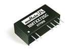
| 描述 | CONV DC/DC 3W 5VIN 24-48-72VOUT隔离式DC/DC转换器 3W 5V - -24/-48/-72V Triple Output |
| 产品分类 | DC DC ConvertersDC/DC转换器 |
| 品牌 | Murata Power Solutions |
| 产品手册 | |
| 产品图片 |
|
| rohs | RoHS 合规性豁免无铅 / 符合限制有害物质指令(RoHS)规范要求 |
| 产品系列 | 隔离式DC/DC转换器,Murata Power Solutions NMT0572SCNMT |
| 数据手册 | |
| 产品型号 | NMT0572SC |
| 产品 | Isolated |
| 产品培训模块 | http://www.digikey.cn/PTM/IndividualPTM.page?site=cn&lang=zhs&ptm=21791 |
| 产品目录页面 | |
| 产品种类 | 隔离式DC/DC转换器 |
| 其它名称 | 811-1583-5 |
| 功率(W)-制造系列 | 3W |
| 功率(W)-最大值 | 3W |
| 包装 | 管件 |
| 商标 | Murata Power Solutions |
| 大小/尺寸 | 0.86" 长 x 0.30" 宽 x 0.44" 高(21.8mm x 7.6mm x 11.2mm) |
| 安装类型 | 通孔 |
| 封装 | Tube |
| 封装/外壳 | 8-SIP 模块(6 引线) |
| 封装/箱体尺寸 | SIP |
| 工作温度 | -40°C ~ 85°C |
| 工厂包装数量 | 23 |
| 效率 | 85% |
| 标准包装 | 23 |
| 特性 | - |
| 电压-输入(最大值) | 5.5V |
| 电压-输入(最小值) | 4.5V |
| 电压-输出1 | -24V |
| 电压-输出2 | -48V |
| 电压-输出3 | -72V |
| 电压-隔离 | 1kV(1000V) |
| 电流-输出(最大值) | 42mA,21A,14A |
| 类型 | 隔离模块 |
| 系列 | NMT |
| 绝缘电压 | 1 kV |
| 输入电压—公称值 | 5 V |
| 输入电压范围 | 4.5 V to 5.5 V |
| 输出功率 | 3 W |
| 输出数 | 3 |
| 输出电压—通道1 | - 24 V |
| 输出电压—通道2 | 48 V |
| 输出电压—通道3 | - 72 V |
| 输出电流—通道 | 14 mA |
| 输出电流—通道1 | 0.042 A |
| 输出电流—通道2 | 126 mA |
| 输出端数量 | 3 |


- 商务部:美国ITC正式对集成电路等产品启动337调查
- 曝三星4nm工艺存在良率问题 高通将骁龙8 Gen1或转产台积电
- 太阳诱电将投资9.5亿元在常州建新厂生产MLCC 预计2023年完工
- 英特尔发布欧洲新工厂建设计划 深化IDM 2.0 战略
- 台积电先进制程称霸业界 有大客户加持明年业绩稳了
- 达到5530亿美元!SIA预计今年全球半导体销售额将创下新高
- 英特尔拟将自动驾驶子公司Mobileye上市 估值或超500亿美元
- 三星加码芯片和SET,合并消费电子和移动部门,撤换高东真等 CEO
- 三星电子宣布重大人事变动 还合并消费电子和移动部门
- 海关总署:前11个月进口集成电路产品价值2.52万亿元 增长14.8%


PDF Datasheet 数据手册内容提取
NMT Series www.murata-ps.com Triple Output 3W DC/DC Converters SELECTION GUIDE Nominal Nominal Output Current1 Output Current2 Input Output MTTF3 Order Code Output Min. Load Full Load Min. Load Full Load Voltage Voltage V V mA mA mA mA kHrs -VOUT1 -24 1.4 42 4.2 126 NMT0572SC 5 -VOUT2 -48 0.7 21 2.1 63 145 -VOUT3 -72 0.5 14 1.4 42 -VOUT1 -24 1.4 42 4.2 126 NMT1272SC 12 -VOUT2 -48 0.7 21 2.1 63 145 -VOUT3 -72 0.5 14 1.4 42 FEATURES When operated with additional external load capacitance the rise time of the input voltage will determine the maximum external capacitance value for guaranteed start up. The slower the rise time of the input voltage the greater the maximum value of the (cid:132)(cid:3)RoHS compliant additional external capacitance for reliable start up. (cid:132)(cid:3)Triple outputs (-24V, -48V & -72V) INPUT CHARACTERISTICS (cid:132)(cid:3)Input/output isolation 1kVDC Parameter Conditions Min. Typ. Max. Units NMT0572SC 4.5 5.0 5.5 (cid:132)(cid:3)Power sharing on outputs Voltage range V NMT1272SC 10.8 12 13.2 (cid:132)(cid:3)Industrial temperature range NMT0572SC 85 Ripple current (IRIPPLE) mA NMT1272SC 66 (cid:132)(cid:3)UL 94V-0 package material Zero load input current NMT0572SC, 0% output load 50 80 mA (cid:132)(cid:3)Internal SMD construction (ICCZL) NMT1272SC, 0% output load 27.5 50 (cid:132)(cid:3)Toroidal magnetics OUTPUT CHARACTERISTICS (cid:132)(cid:3)No external components required Parameter Conditions Min. Typ. Max. Units (cid:132)(cid:3)Power density 1.65W/cm3 Total Rated Power (POUT) Total of all outputs or any single output 0.1 3.0 W Single Channel Voltage Set POUT = 100mW 0 10 % DESCRIPTION Point Accuracy POUT = 3W -7.5 2.5 The NMT series is a range of DC/DC convert- Output Voltage - VOUT1 POUT = 100mW 24 26.4 ers offering three output voltages of -24V, -48V POUT = 3W 22.2 24.6 and -72V from a single isolated 5V or 12V input Output Voltage - VOUT2 POUT = 100mW 48 52.8 V voltage. The product is designed for use with POUT = 3W 44.4 49.2 telecommunications circuits requiring an on board Output Voltage - VOUT3 POUT = 100mW 72 79.2 supply for the -72V RING-TIP connection service POUT = 3W 66.6 73.8 generated from a nominal 5V or 12V DC input Line regulation VIN = 90% to 110% of nominal 1.01 1.2 % supply rail. The device also offers battery level Load regulation POUT = 100mW to 3W 8 15 voltages of -24V and -48V for access control and Ripple & Noise DC to 20MHz single channel (24V) 220 400 mV data pump IC’s. The product is packaged in an 8 pin SIP case for minimum PCB footprint. The ISOLATION CHARACTERISTICS rated power may be shared or drawn from any Parameter Conditions Min. Typ. Max. Units one output providing the total output load does not Isolation test voltage Flash tested for 1 second 1000 VDC exceed 3W. NMT0572SC, 1MHz, 1V 65 Isolation Capacitance pF NMT1272SC, 1MHz, 1V 130 Insulation Resistance 1000VDC 1 10 GΩ ABSOLUTE MAXIMUM RATINGS Short-circuit protection4 1 second Lead temperature 1.5mm from case for 10 seconds 300°C Input Voltage VIN, NMT0572SC 7V Input voltage VIN, NMT1272SC 15V 1. Assuming all 3 channels are equally loaded. 2. Assuming only 1 channel is loaded. 3. Calculated using MIL-HDBK-217F with nominal input voltage at full load. For full details go to 4. Supply voltage must be disconnected at the end of the short circuit duration. www.murata-ps.com/rohs All specifications typical at TA=25°C, nominal input voltage and rated output current unless otherwise specified. www.murata-ps.com/support KDC_NMT.E04 Page 1 of 4
NMT Series Triple Output 3W DC/DC Converters GENERAL CHARACTERISTICS Parameter Conditions Min. Typ. Max. Units Efficiency All channels or any single channel 75 85 % Switching frequency 85 kHz TEMPERATURE CHARACTERISTICS Parameter Conditions Min. Typ. Max. Units Operating temperature -40 85 Storage -50 125 °C Case temperature rise above 1 litre static air chamber 27 ambient OUTPUT VOLTAGE CONFIGURATION Although the output is described for negative rails, the input and output circuits are iternally isolated hence positive rails can also be generated, or a mixture of positive and negative. The output +VOUT rail reference can be taken from any of the output terminals to give the range of outputs as described in the Output Voltage Configura- tions table below. Channel Name Standard Ref Option 1 Option 2 Option 3 +VOUT OV +24V +48V +72V -VOUT1 -24V OV +24V +48V -VOUT2 -48V -24V OV +24V -VOUT3 -72V -48V -24V OV POWER SHARING The 3W total power delivery can be taken from either a single channel, or from any combination of all three channels. This allows an enormous amount of flexibility, especially when combined with the selectable output OV reference. For example, using the option 2 output configuration; -24V at 0.5W, +24V at 1W and +48V at 1.5W power supplies are available from a single NMT device. PERFORMANCE CHARACTERISTICS NMT0572SC - Channel -VOUT1 (24V NOM) NMT1272SC - Channel -VOUT1 (24V NOM) (cid:18)(cid:17)(cid:17) (cid:21)(cid:17) (cid:18)(cid:17)(cid:17) (cid:21)(cid:17) (cid:25)(cid:17) (cid:20)(cid:23) (cid:25)(cid:17) (cid:20)(cid:23) (cid:38)(cid:71)(cid:109)(cid:68)(cid:74)(cid:70)(cid:79)(cid:68)(cid:90)(cid:1)(cid:9)(cid:6)(cid:10) (cid:23)(cid:21)(cid:19)(cid:17)(cid:17)(cid:17) (cid:48)(cid:86)(cid:85)(cid:81)(cid:86)(cid:85)(cid:1)(cid:55)(cid:80)(cid:77)(cid:85)(cid:66)(cid:72)(cid:70)(cid:1)(cid:9)(cid:55)(cid:10) (cid:20)(cid:19)(cid:19)(cid:19)(cid:25)(cid:21) (cid:38)(cid:71)(cid:109)(cid:68)(cid:74)(cid:70)(cid:79)(cid:68)(cid:90)(cid:1)(cid:9)(cid:6)(cid:10) (cid:23)(cid:21)(cid:19)(cid:17)(cid:17)(cid:17) (cid:48)(cid:86)(cid:85)(cid:81)(cid:86)(cid:85)(cid:1)(cid:55)(cid:80)(cid:77)(cid:85)(cid:66)(cid:72)(cid:70)(cid:1)(cid:9)(cid:55)(cid:10) (cid:20)(cid:19)(cid:19)(cid:19)(cid:25)(cid:21) (cid:17)(cid:17) (cid:17)(cid:15)(cid:22) (cid:18)(cid:15)(cid:17) (cid:18)(cid:15)(cid:22) (cid:19)(cid:15)(cid:17) (cid:19)(cid:15)(cid:22) (cid:20)(cid:15)(cid:17) (cid:19)(cid:17)(cid:17) (cid:17)(cid:15)(cid:22) (cid:18)(cid:15)(cid:17) (cid:18)(cid:15)(cid:22) (cid:19)(cid:15)(cid:17) (cid:19)(cid:15)(cid:22) (cid:20)(cid:15)(cid:17) (cid:17)(cid:17) (cid:17)(cid:15)(cid:22) (cid:18)(cid:15)(cid:17) (cid:18)(cid:15)(cid:22) (cid:19)(cid:15)(cid:17) (cid:19)(cid:15)(cid:22) (cid:20)(cid:15)(cid:17) (cid:19)(cid:17)(cid:17) (cid:17)(cid:15)(cid:22) (cid:18)(cid:15)(cid:17) (cid:18)(cid:15)(cid:22) (cid:19)(cid:15)(cid:17) (cid:19)(cid:15)(cid:22) (cid:20)(cid:15)(cid:17) (cid:48)(cid:86)(cid:85)(cid:81)(cid:86)(cid:85)(cid:1)(cid:49)(cid:80)(cid:88)(cid:70)(cid:83)(cid:1)(cid:9)(cid:56)(cid:10) (cid:48)(cid:86)(cid:85)(cid:81)(cid:86)(cid:85)(cid:1)(cid:49)(cid:80)(cid:88)(cid:70)(cid:83)(cid:1)(cid:9)(cid:56)(cid:10) (cid:48)(cid:86)(cid:85)(cid:81)(cid:86)(cid:85)(cid:1)(cid:49)(cid:80)(cid:88)(cid:70)(cid:83)(cid:1)(cid:9)(cid:56)(cid:10) (cid:48)(cid:86)(cid:85)(cid:81)(cid:86)(cid:85)(cid:1)(cid:49)(cid:80)(cid:88)(cid:70)(cid:83)(cid:1)(cid:9)(cid:56)(cid:10) NMT0572SC - Channel -VOUT2 (48V NOM) NMT1272SC - Channel -VOUT2 (48V NOM) (cid:18)(cid:17)(cid:17) (cid:25)(cid:17) (cid:18)(cid:17)(cid:17) (cid:25)(cid:17) (cid:25)(cid:17) (cid:24)(cid:19) (cid:25)(cid:17) (cid:24)(cid:19) (cid:38)(cid:71)(cid:109)(cid:68)(cid:74)(cid:70)(cid:79)(cid:68)(cid:90)(cid:1)(cid:9)(cid:6)(cid:10) (cid:23)(cid:21)(cid:17)(cid:17) (cid:48)(cid:86)(cid:85)(cid:81)(cid:86)(cid:85)(cid:1)(cid:55)(cid:80)(cid:77)(cid:85)(cid:66)(cid:72)(cid:70)(cid:1)(cid:9)(cid:55)(cid:10) (cid:23)(cid:22)(cid:21)(cid:23) (cid:38)(cid:71)(cid:109)(cid:68)(cid:74)(cid:70)(cid:79)(cid:68)(cid:90)(cid:1)(cid:9)(cid:6)(cid:10) (cid:23)(cid:21)(cid:17)(cid:17) (cid:48)(cid:86)(cid:85)(cid:81)(cid:86)(cid:85)(cid:1)(cid:55)(cid:80)(cid:77)(cid:85)(cid:66)(cid:72)(cid:70)(cid:1)(cid:9)(cid:55)(cid:10) (cid:23)(cid:22)(cid:21)(cid:23) (cid:19)(cid:17) (cid:21)(cid:25) (cid:19)(cid:17) (cid:21)(cid:25) (cid:17) (cid:21)(cid:17) (cid:17) (cid:21)(cid:17) (cid:17) (cid:17)(cid:15)(cid:22) (cid:18)(cid:15)(cid:17) (cid:18)(cid:15)(cid:22) (cid:19)(cid:15)(cid:17) (cid:19)(cid:15)(cid:22) (cid:20)(cid:15)(cid:17) (cid:17) (cid:17)(cid:15)(cid:22) (cid:18)(cid:15)(cid:17) (cid:18)(cid:15)(cid:22) (cid:19)(cid:15)(cid:17) (cid:19)(cid:15)(cid:22) (cid:20)(cid:15)(cid:17) (cid:17) (cid:17)(cid:15)(cid:22) (cid:18)(cid:15)(cid:17) (cid:18)(cid:15)(cid:22) (cid:19)(cid:15)(cid:17) (cid:19)(cid:15)(cid:22) (cid:20)(cid:15)(cid:17) (cid:17) (cid:17)(cid:15)(cid:22) (cid:18)(cid:15)(cid:17) (cid:18)(cid:15)(cid:22) (cid:19)(cid:15)(cid:17) (cid:19)(cid:15)(cid:22) (cid:20)(cid:15)(cid:17) (cid:48)(cid:86)(cid:85)(cid:81)(cid:86)(cid:85)(cid:1)(cid:49)(cid:80)(cid:88)(cid:70)(cid:83)(cid:1)(cid:9)(cid:56)(cid:10) (cid:48)(cid:86)(cid:85)(cid:81)(cid:86)(cid:85)(cid:1)(cid:49)(cid:80)(cid:88)(cid:70)(cid:83)(cid:1)(cid:9)(cid:56)(cid:10) (cid:48)(cid:86)(cid:85)(cid:81)(cid:86)(cid:85)(cid:1)(cid:49)(cid:80)(cid:88)(cid:70)(cid:83)(cid:1)(cid:9)(cid:56)(cid:10) (cid:48)(cid:86)(cid:85)(cid:81)(cid:86)(cid:85)(cid:1)(cid:49)(cid:80)(cid:88)(cid:70)(cid:83)(cid:1)(cid:9)(cid:56)(cid:10) NMT0572SC - Channel -VOUT3 (72V NOM) NMT1272SC - Channel -VOUT3 (72V NOM) (cid:18)(cid:17)(cid:17) (cid:18)(cid:19)(cid:17) (cid:18)(cid:17)(cid:17) (cid:18)(cid:19)(cid:17) (cid:25)(cid:17) (cid:18)(cid:17)(cid:25) (cid:25)(cid:17) (cid:18)(cid:17)(cid:25) (cid:38)(cid:71)(cid:109)(cid:68)(cid:74)(cid:70)(cid:79)(cid:68)(cid:90)(cid:1)(cid:9)(cid:6)(cid:10) (cid:23)(cid:21)(cid:19)(cid:17)(cid:17)(cid:17) (cid:48)(cid:86)(cid:85)(cid:81)(cid:86)(cid:85)(cid:1)(cid:55)(cid:80)(cid:77)(cid:85)(cid:66)(cid:72)(cid:70)(cid:1)(cid:9)(cid:55)(cid:10) (cid:26)(cid:25)(cid:24)(cid:23)(cid:21)(cid:19) (cid:38)(cid:71)(cid:109)(cid:68)(cid:74)(cid:70)(cid:79)(cid:68)(cid:90)(cid:1)(cid:9)(cid:6)(cid:10) (cid:23)(cid:21)(cid:19)(cid:17)(cid:17)(cid:17) (cid:48)(cid:86)(cid:85)(cid:81)(cid:86)(cid:85)(cid:1)(cid:55)(cid:80)(cid:77)(cid:85)(cid:66)(cid:72)(cid:70)(cid:1)(cid:9)(cid:55)(cid:10) (cid:26)(cid:25)(cid:24)(cid:23)(cid:21)(cid:19) (cid:17) (cid:23)(cid:17) (cid:17) (cid:23)(cid:17) (cid:17) (cid:17)(cid:15)(cid:22) (cid:18)(cid:15)(cid:17) (cid:18)(cid:15)(cid:22) (cid:19)(cid:15)(cid:17) (cid:19)(cid:15)(cid:22) (cid:20)(cid:15)(cid:17) (cid:17) (cid:17)(cid:15)(cid:22) (cid:18)(cid:15)(cid:17) (cid:18)(cid:15)(cid:22) (cid:19)(cid:15)(cid:17) (cid:19)(cid:15)(cid:22) (cid:20)(cid:15)(cid:17) (cid:17) (cid:17)(cid:15)(cid:22) (cid:18)(cid:15)(cid:17) (cid:18)(cid:15)(cid:22) (cid:19)(cid:15)(cid:17) (cid:19)(cid:15)(cid:22) (cid:20)(cid:15)(cid:17) (cid:17) (cid:17)(cid:15)(cid:22) (cid:18)(cid:15)(cid:17) (cid:18)(cid:15)(cid:22) (cid:19)(cid:15)(cid:17) (cid:19)(cid:15)(cid:22) (cid:20)(cid:15)(cid:17) (cid:48)(cid:86)(cid:85)(cid:81)(cid:86)(cid:85)(cid:1)(cid:49)(cid:80)(cid:88)(cid:70)(cid:83)(cid:1)(cid:9)(cid:56)(cid:10) (cid:48)(cid:86)(cid:85)(cid:81)(cid:86)(cid:85)(cid:1)(cid:49)(cid:80)(cid:88)(cid:70)(cid:83)(cid:1)(cid:9)(cid:56)(cid:10) (cid:48)(cid:86)(cid:85)(cid:81)(cid:86)(cid:85)(cid:1)(cid:49)(cid:80)(cid:88)(cid:70)(cid:83)(cid:1)(cid:9)(cid:56)(cid:10) (cid:48)(cid:86)(cid:85)(cid:81)(cid:86)(cid:85)(cid:1)(cid:49)(cid:80)(cid:88)(cid:70)(cid:83)(cid:1)(cid:9)(cid:56)(cid:10) www.murata-ps.com/support KDC_NMT.E04 Page 2 of 4
NMT Series Triple Output 3W DC/DC Converters APPLICATION NOTES RIPPLE SPECIFICATION The output ripple for the NMT series is higher than standard for a Murata Power Solutions DC/DC converter. This is due to using low value ceramic capacitors internally for longer life perfomance of the component and the superimposition of ripples between each output channel. Consequently with a maximum 400mV ripple per output channel, at -72V the ripple is potentially three times this value (1.2V). The ripple will always be additively superimposed since the output windings are synchronized. To reduce ripple, external capacitors are recommended with a value of 1μF per channel (see figure 1). This typically reduces the ripple to 50mV per channel. Further ripple reduction can be achieved by use of series inductors on each output channel plus additional external capacitors to form a pi-filter with the internal capaci- tors of the device. SLIC CIRCUITS The primary application for the NMT series is in subscriber line interface circuits (SLIC’s), particularly for the Figure 1. VOUT3 Output Ripple Integrated Services Digital Network (ISDN). The NMT can also be used in standard telecommunications circuits Top: No external capacitors where a local power source is preferred to the telephone system power due to either the power quality of the Bottom: 1μF per channel external capacitors telecommunications system power supply or to avoid potential power line disturbances, such as lightening sAtnrioktehse ra anpdp alicccaetisosn s awreitac hisin ign, fiwbhriec-hin w-tihlle e-flfoeocpt (tFhIeT Lta) rogre rta cdirioc-uiint -ftuhnec-tloioonp. (RITL) interfacing via a standard tele- (cid:12)(cid:55)(cid:42)(cid:47) (cid:47)(cid:46)(cid:53)(cid:17)(cid:37)(cid:22)(cid:36)(cid:24)(cid:19)(cid:14)(cid:52)(cid:55)(cid:48)(cid:36)(cid:54)(cid:53)(cid:20)(cid:14)(cid:24)(cid:19)(cid:55) (cid:34)(cid:55)(cid:35)(cid:46)(cid:34)(cid:53)(cid:18)(cid:37)(cid:1)(cid:9)(cid:34)(cid:78)(cid:24)(cid:26)(cid:51)(cid:24)(cid:26)(cid:10)(cid:34) (cid:53)(cid:42)(cid:49) communication SLIC, where the usual telecommunication battery voltage is not available due to the transmis- (cid:14)(cid:55)(cid:48)(cid:54)(cid:53)(cid:19)(cid:14)(cid:21)(cid:25)(cid:55) (cid:55)(cid:35)(cid:34)(cid:53)(cid:19) sbiooons mt ceirdciau iitns uansed (afitb erxec ohra rnagdeios )b. Ient wpeaertnic tuhlaer ,fi FbIrTeL/r/aRdITioL ainntde rwfaicree sm deidreiac.tly on PC cards, in local monitor and (cid:14)(cid:55)(cid:42)(cid:47) (cid:37)(cid:36) (cid:14)(cid:55)(cid:48)(cid:54)(cid:53)(cid:18)(cid:14)(cid:48)(cid:19)(cid:55)(cid:21)(cid:55) (cid:55)(cid:47)(cid:38)(cid:40) (cid:35)(cid:40)(cid:47)(cid:37) (cid:35) (cid:51)(cid:42)(cid:47)(cid:40) The supply rails can be used for ringing generators as well as SLIC circuits or where both are combined, such as in the AMD AM79R79 Ringing SLIC device (see figure 2). The -72V rail is used primarily for the generation of the Figure 2. Supply for Ringing SLIC Device ringing signal (VBAT1), the -48V rail is used to supply in line access circuitry (VBAT2) and the -24V supply for the on-chip regulator for the logic interface (VNEG). Alternative devices from other manufacturers could use the -24V output for their internal circuit supply and -72V for ringing. TECHNICAL NOTES ISOLATION VOLTAGE ‘Hi Pot Test’, ‘Flash Tested’, ‘Withstand Voltage’, ‘Proof Voltage’, ‘Dielectric Withstand Voltage’ & ‘Isolation Test Voltage’ are all terms that relate to the same thing, a test voltage, applied for a specified time, across a component designed to provide electrical isolation, to verify the integrity of that isolation. Murata Power Solutions NMT series of DC/DC converters are all 100% production tested at their stated isolation voltage. This is 1kVDC for 1 second. A question commonly asked is, “What is the continuous voltage that can be applied across the part in normal operation?” For a part holding no specific agency approvals, such as the NMT series, both input and output should normally be maintained within SELV limits i.e. less than 42.4V peak, or 60VDC. The isolation test voltage represents a measure of immunity to transient voltages and the part should never be used as an element of a safety isolation system. The part could be expected to function correctly with several hundred volts offset applied continuously across the isolation barrier; but then the circuitry on both sides of the barrier must be regarded as operating at an unsafe voltage and further isolation/insulation systems must form a barrier between these circuits and any user-accessible circuitry according to safety standard requirements. REPEATED HIGH-VOLTAGE ISOLATION TESTING It is well known that repeated high-voltage isolation testing of a barrier component can actually degrade isolation capability, to a lesser or greater degree depending on materials, construction and environment. The NMT series has toroidal isolation transformers, with no additional insulation between primary and secondary windings of enameled wire. While parts can be expected to withstand several times the stated test voltage, the isolation capability does depend on the wire insulation. Any material, including this enamel (typically polyurethane) is susceptible to eventual chemical degradation when subject to very high applied voltages thus implying that the number of tests should be strictly limited. We therefore strongly advise against repeated high voltage isolation testing, but if it is absolutely required, that the voltage be reduced by 20% from specified test voltage. This consideration equally applies to agency recognized parts rated for better than functional isolation where the wire enamel insulation is always supplemented by a further insulation system of physical spacing or barriers. www.murata-ps.com/support KDC_NMT.E04 Page 3 of 4
NMT Series Triple Output 3W DC/DC Converters PACKAGE SPECIFICATIONS MECHANICAL DIMENSIONS PIN CONNECTIONS - 8 PIN SIP 0.858 Pin Function (21.80) 1 +VIN 2 -VIN 0.295 (7.50) 5 +VOUT 6 -VOUT1 7 -VOUT2 8 -VOUT3 0.437 (11.10) NMT0572SC 0.022 (0.55) TUBE OUTLINE DIMENSIONS XYYWW 0.018 (0.45) (cid:17)(cid:15)(cid:19)(cid:20)(cid:23)(cid:1) (cid:17)(cid:15)(cid:22)(cid:22)(cid:26)(cid:1)(cid:9)(cid:18)(cid:21)(cid:15)(cid:19)(cid:17)(cid:10) (cid:9)(cid:23)(cid:15)(cid:17)(cid:17)(cid:10) 1 2 5 6 7 8 0.022 (0.55) 0.181 (4.60) 0.018 (0.45) 0.142 (3.60) (cid:17)(cid:15)(cid:18)(cid:26)(cid:24)(cid:1)(cid:9)(cid:22)(cid:15)(cid:17)(cid:17)(cid:10) 0.046 0.0118 (0.30) (cid:17)(cid:15)(cid:19)(cid:17)(cid:22)(cid:1)(cid:9)(cid:22)(cid:15)(cid:19)(cid:17)(cid:10) (1.17) 0.0078 (0.20) (cid:17)(cid:15)(cid:17)(cid:22)(cid:26)(cid:1)(cid:9)(cid:18)(cid:15)(cid:22)(cid:17)(cid:10) 0.083 (2.10) (cid:17)(cid:15)(cid:17)(cid:19)(cid:21)(cid:156)(cid:17)(cid:15)(cid:17)(cid:17)(cid:23)(cid:1) (cid:9)(cid:17)(cid:15)(cid:23)(cid:17)(cid:156)(cid:17)(cid:15)(cid:18)(cid:22)(cid:10) All dimensions in inches ±0.01 (mm ±0.25mm). All pins on a 0.1 (2.54) pitch and within Unless otherwise stated all dimensions in inches ±0.02 (mm ±0.5mm). ±0.01 (0.25) of true position. Weight: 3.85g Tube length : 20.47±0.079 (520mm±2mm). Tube Quantity : 23 RECOMMENDED FOOTPRINT DETAILS` RoHS COMPLIANT INFORMATION (cid:17)(cid:15)(cid:17)(cid:21)(cid:22)(cid:1)(cid:9)(cid:18)(cid:15)(cid:18)(cid:22)(cid:10) (cid:140) (cid:17)(cid:15)(cid:17)(cid:20)(cid:26)(cid:1)(cid:9)(cid:18)(cid:15)(cid:17)(cid:17)(cid:10) (cid:23)(cid:1)(cid:41)(cid:48)(cid:45)(cid:38)(cid:52) This series is compatible with RoHS soldering systems with a peak wave solder temperature (cid:17)(cid:15)(cid:17)(cid:17)(cid:20)(cid:26)(cid:21)(cid:1)(cid:9)(cid:17)(cid:15)(cid:18)(cid:10) of 300ºC for 10 seconds. The pin termination finish on this product series is Tin Plate, Hot Dipped over Matte Tin with Nickel Preplate. The series is backward compatible with Sn/Pb (cid:1)(cid:17)(cid:15)(cid:18)(cid:1)(cid:9)(cid:19)(cid:15)(cid:22)(cid:21)(cid:10) soldering systems. For further information, please visit www.murata-ps.com/rohs (cid:1)(cid:17)(cid:15)(cid:18)(cid:1)(cid:9)(cid:19)(cid:15)(cid:22)(cid:21)(cid:10) Unless otherwise stated all dimensions in inches ±0.02 (mm ±0.5mm). This product is subject to the following operating requirements Murata Power Solutions, Inc. and the Life and Safety Critical Application Sales Policy: 11 Cabot Boulevard, Mansfield, MA 02048-1151 U.S.A. Refer to: http://www.murata-ps.com/requirements/ ISO 9001 and 14001 REGISTERED Murata Power Solutions, Inc. makes no representation that the use of its products in the circuits described herein, or the use of other technical information contained herein, will not infringe upon existing or future patent rights. The descriptions contained herein do not imply the granting of licenses to make, use, or sell equipment constructed in accordance therewith. Specifications are subject to change without notice. © 2012 Murata Power Solutions, Inc. www.murata-ps.com/support KDC_NMT.E04 Page 4 of 4
Mouser Electronics Authorized Distributor Click to View Pricing, Inventory, Delivery & Lifecycle Information: M urata: NMT1272SC NMT0572SC NMT0572SZC