 Datasheet下载
- 型号: NM485SLC
- 制造商: Murata
- 库位|库存: xxxx|xxxx
- 要求:
| 数量阶梯 | 香港交货 | 国内含税 |
| +xxxx | $xxxx | ¥xxxx |
查看当月历史价格
查看今年历史价格
NM485SLC产品简介:
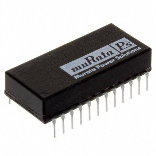
ICGOO电子元器件商城为您提供NM485SLC由Murata设计生产,在icgoo商城现货销售,并且可以通过原厂、代理商等渠道进行代购。 NM485SLC价格参考。MurataNM485SLC封装/规格:数字隔离器, 通用 数字隔离器 1000Vrms 2 通道 2.5Mbps 24-DIP(0.667",16.95mm)。您可以下载NM485SLC参考资料、Datasheet数据手册功能说明书,资料中有NM485SLC 详细功能的应用电路图电压和使用方法及教程。
| 参数 | 数值 |
| 产品目录 | 集成电路 (IC)半导体 |
| 描述 | ISOLATED INTERFACE LP EIA-485RS-485接口IC Iso Dual EIA-485 Driver and Receiver |
| 产品分类 | |
| 品牌 | Murata Power Solutions |
| 产品手册 | |
| 产品图片 |
|
| rohs | RoHS 合规性豁免无铅 / 符合限制有害物质指令(RoHS)规范要求 |
| 产品系列 | 接口 IC,RS-485接口IC,Murata Power Solutions NM485SLCIsoLoop® |
| 数据手册 | |
| 产品型号 | NM485SLC |
| 产品目录页面 | |
| 产品种类 | RS-485接口IC |
| 传播延迟时间ns | 150 ns, 80 ns |
| 供应商器件封装 | 24-DIL |
| 关闭 | Yes |
| 其它名称 | 811-1446-5 |
| 功能 | Transceiver |
| 包装 | 管件 |
| 协议 | RS485 |
| 双工 | 半 |
| 商标 | Murata Power Solutions |
| 安装类型 | 通孔 |
| 安装风格 | Through Hole |
| 封装 | Tube |
| 封装/外壳 | 24-DIP(0.667",16.95mm) |
| 封装/箱体 | DIL-24 |
| 工作温度 | 0°C ~ 60°C |
| 工作温度范围 | 0 C to + 70 C |
| 工作电源电压 | 5 V |
| 工厂包装数量 | 15 |
| 接收器滞后 | 50mV |
| 接收机数量 | 2 Receiver |
| 数据速率 | 2.5 Mb/s |
| 最大功率耗散 | 1 W |
| 最大工作温度 | + 70 C |
| 最小工作温度 | 0 C |
| 标准包装 | 15 |
| 激励器数量 | 2 Driver |
| 电压-电源 | 4.75 V ~ 5.25 V |
| 电源电流 | 25 mA |
| 类型 | 收发器,隔离式 |
| 系列 | NM485SLC |
| 输入电压 | 5 V |
| 驱动器/接收器数 | 1/1 |


- 商务部:美国ITC正式对集成电路等产品启动337调查
- 曝三星4nm工艺存在良率问题 高通将骁龙8 Gen1或转产台积电
- 太阳诱电将投资9.5亿元在常州建新厂生产MLCC 预计2023年完工
- 英特尔发布欧洲新工厂建设计划 深化IDM 2.0 战略
- 台积电先进制程称霸业界 有大客户加持明年业绩稳了
- 达到5530亿美元!SIA预计今年全球半导体销售额将创下新高
- 英特尔拟将自动驾驶子公司Mobileye上市 估值或超500亿美元
- 三星加码芯片和SET,合并消费电子和移动部门,撤换高东真等 CEO
- 三星电子宣布重大人事变动 还合并消费电子和移动部门
- 海关总署:前11个月进口集成电路产品价值2.52万亿元 增长14.8%

PDF Datasheet 数据手册内容提取
NM485SLC www.murata-ps.com Low Power Isolated EIA-485 Driver and Receiver ELECTRICAL CHARACTERISTICS Parameter Test conditions Min. Typ. Max. Units Supply voltage, VCC 4.75 5.0 5.25 V Isolated reference voltage, VREF 5.0 +VREF Current RL=54Ω 25 mA High level input voltage, VIH 2.8 V D ENABLE, R ENABLE and DIN Low level input voltage, VIL 0.8 V Common mode output voltage, VOC -7.0 12 V High level output current IOH Driver -60 mA Low level output current, IOL 60 mA Common mode input voltage, VIC ±12 V FEATURES Differential input voltage, VID Receiver ±12 V High level output current, IOH -5.0 mA (cid:132)(cid:3)RoHS compliant Low level output current, IOL 25 mA (cid:132)(cid:3)Site compatible with NM485D RECEIVER ELECTRICAL CHARACTERISTICS (cid:132)(cid:3)Single 5V supply Parameter Test conditions Min. Typ. Max. Units (cid:132)(cid:3)Thermal shutdown protection High threshold differential input, VTH VO=2.7V, IO=-0.4mA 0.2 V Low threshold differential input, VTL VO=0.5V, IO=16mA -0.2 V (cid:132)(cid:3)EIA-485 and CCITT V.10 & V.11 compatible Input hysteresis, ΔVT 70 mV (cid:132)(cid:3)Differential driver and receiver High level output voltage, VOH VID=200mV, IOH=-5.0mA 2.7 V Low level output voltage, VOL VID=-200mV, IOL=25mA 0.8 V (cid:132)(cid:3)Driver tri-state outputs active high enable Other input at 0V, VI=12V 1.0 (cid:132)(cid:3)Low Profile 24 pin DIL package style Line input current, II Other input at 0V, VI=-7.0V -0.8 mA (cid:132)(cid:3)1kVrms Isolation Short circuit output current, IOS 85 mA Input resistance, RI 12 KΩ (cid:132)(cid:3)Thermal shutdown protection RECEIVER SWITCHING CHARACTERISTICS DESCRIPTION Parameter Test conditions Min. Typ. Max. Units Propagation delay time L to H, TPLH VID=-1.5V to 1.5V, CL=15pF 150 180 ns The NM485SLC is a low power electrically iso- Propagation delay time H to L, TPHL 130 150 ns lated differential driver and receiver designed for bi-directional data communication or multipoint Output disable time from high level CL=15pF 90 150 ns bus transmission at rates up to 2.5Mbits per Output disable time from low level CL=15pF 90 150 ns second. The device combines a tri-state dif- Output enable time to high level CL=15pF 130 150 ns ferential line driver and a differential input line Output enable time to low level CL=15pF 80 150 ns receiver. The driver and receiver have active high RECEIVER FUNCTION TABLE and active low enables, respectively, which can be connected together to function as direction Differential inputs A-B R ENABLE ROUT control. The receiver features a high output state VID≥0.2V Low level High level when the inputs are left open. Thermal shutdown -0.2V<VID<+0.2V Low level Undefined protection forces the driver into a high imped- VID≤-0.2V Low level Low level ance state, under line fault conditions. No external Irrelevant High level High level components are needed as a single 5V supply ISOLATION CHARACTERISTICS powers all functions either side of the isolation Parameter Conditions Min. Typ. Max. Units boundary. The device is supplied in a low profile 24 pin plastic package. Isolation test voltage Flash tested for 1 second 1000 Vrms Isolation capacitance 40 pF ABSOLUTE MAXIMUM RATINGS Supply voltage VCC with respect to pin 11 7V Input voltage D ENABLE, R ENABLE and DIN 7V Receiver differential input voltage range -14V to +14V Output voltage range, driver -14V to +14V Power dissipation 1000mW Data transmission rate 2.5Mbps Lead temperature 1.5mm from case for 10 seconds 300ºC For full details go to www.murata-ps.com/rohs All data taken at TA=25°C, VCC=5V. www.murata-ps.com/support KDC_NM485SLC.A05 Page 1 of 5
NM485SLC Low Power Isolated EIA-485 Driver and Receiver DRIVER ELECTRICAL CHARACTERISTICS Parameter Test conditions Min. Typ. Max. Units High level output voltage, VOH IOH=-25mA 3.7 V Low level output voltage, VOL IOH=25mA 1.1 V Differential output voltage, VOD1 IO=0 1.5 6.0 V RL=100Ω 2.0 V Differential output voltage, VOD2 RL=54Ω 1.5 5.0 V Change in magnitude of differential output voltage, ΔVOD ±0.2 V Common mode output voltage, ΔVOC RL=54Ω or 100Ω -1.0 3.0 V Change in magnitude of common mode output voltage, ΔVOC ±0.2 V Output current power off, IO VCC=0, VO=-7.0V to 12V ±100 μA High level input current, IIH VIH=4.0V 2.0 20 μA Low level input current, IIL VIL=0.8V -8.0 -15 mA Short circuit output current, IOS VO=-7.0V1 -250 mA VO=12V1 250 mA DRIVER SWITCHING CHARACTERISTICS Parameter Test conditions Min. Typ. Max. Units Differential output delay time, TDD RL=54Ω, CL=50pF 20 25 ns Output disable time from high level, TPHZ RL=110Ω, CL=50pF 70 120 ns Output disable time from low level, TPLZ RL=110Ω, CL=50pF 60 120 ns Propagation delay time L to H, TPLH 80 150 ns RL=27Ω, CL=50pF Propagation delay time H to L, TPHL 80 150 ns Differential output transition time, TTD RL=54Ω, CL=50pF 150 300 ns Output enable time to high level, TPZH RL=110Ω, CL=50pF 80 120 ns Output enable time to low level, TPZL RL=110Ω, CL=50pF 80 120 ns DRIVER FUNCTION TABLE DIN D ENABLE DY Output DZ Output High level High level High level Low level Low level High level Low level High level Irrelevant Low level High impedance High impedance TEMPERATURE CHARACTERISTICS Parameter Min. Typ. Max. Units Operating free-air temperature range 0 70 ºC Storage temperature range -40 125 ºC RoHS COMPLIANCE INFORMATION This series is compatible with RoHS soldering systems with a peak wave solder temperature of 300ºC for 10 seconds. The pin termination finish on this product series is Matte Tin over Nickel Preplate. The series is backward compatible with Sn/Pb soldering systems. For further information, please visit www.murata-ps.com/rohs 1. Duration of short circuit should not exceed 1 second. www.murata-ps.com/support KDC_NM485SLC.A05 Page 2 of 5
NM485SLC Low Power Isolated EIA-485 Driver and Receiver APPLICATION NOTES The increased use of balanced data transmission lines, (distributing data to several system components and peripherals over relatively long lines) has brought about the need for multiple driver/receiver combinations on a single twisted pair line. This resulted in an upgraded version of EIA RS-422, named EIA-485. EIA-485 takes into account EIA RS-422 requirements for balanced line data transmission, and allows for multiple drivers and receivers. The NM485SLC is a low power isolated differential interface providing EIA-485 compatibility. The use of a differential communications interface such as the NM485SLC allows data transmission at high rates and over long distances to be accomplished. This is because effects of external noise sources and cross talk are much less pronounced on the data signal. Any external noise source coupling onto the differential lines will appear as an extra common mode voltage which the receiver is insensitive to. The difference between the signal levels on the two lines will therefore remain the same. Similarly a change in the local ground potential at one end of the line will appear as just another change in the common mode voltage level of the signals. Twisted pair cable is commonly used for differential communications since its twisted nature tends to cause cancellation of the magnetic fields generated by the current flowing through each wire, thus reducing the effective inductance of the pair. Computer and industrial serial interfacing are areas where noise can seriously affect the integrity of data transfer, and a proven route to improve noise performance for any interface system is galvanic isolation. Galvanic isolation removes the ground loop currents from data lines and hence the impressed noise voltage which affects the signal is also eliminated. The isolation feature of the NM485SLC also means that common mode noise effects are removed and many forms of radiated noise are reduced to negligible limits. The NM485SLC has driver thermal shutdown protection which protects the device from line fault conditions. If the outputs of the driver are accidently shorted to a power supply or low impedance source, up to 250mA can flow through the part. The thermal shutdown circuit disables the driver output when the internal temperature of the I.C. reaches 150ºC and turns it back on when the temperature cools to 130ºC. If two or more NM485SLCs are used and drivers are shorted directly, the driver outputs can not supply enough current to activate the thermal shutdown. Thus the internal shutdown circuit will not prevent contention faults when two drivers are active on the same bus at the same time. Figure 1 demonstrates how the differential lines of the NM485SLC can be connected to form a transceiver. Data direction is controlled by the driver enable and receiver enable pins. This means the device can receive when the receiver enable is low and transmit when the driver enable is high. As the driver is active high, to reduce the power dissipation even further, it is advisable to disable the driver when not transmitting data. Some data encoding schemes require the output of the receiver to maintain a known state, usually a logic 1, when the data transmission is complete and all drivers are forced into three-state, high impedance. The NM485SLC receiver has a fail safe feature which guarantees the output to be in a logic 1 state when the receiver inputs are left floating (open circuit). However, when the cable is terminated with 120Ω, the differential inputs to the receiver are shorted together, not left floating. Since the receiver has about 70mV hysteresis, the output will maintain the last bit received. Implementing an isolated LONWORKS (™) network using the NM485SLC The Echleon LONWORKS (Local Operating Network) network is designed to be used in industrial applications in which other electrical equipment is operated. Often the LON(R) will be the method of controlling machinery or sensing machine activity. The environment is therefore likely to be electrically noisy and to reduce the possibility of data corruption, an isolated network communications system is a preferred method of data transfer. The EIA-485 standard provides a method of achieving multi-point (multi-drop) data transmission over balanced twisted pair transmission lines. The standard is a differential scheme offering a large degree of common mode immunity compared to single ended schemes. The isolated differential method offers the highest common mode and line noise immunity for wire based systems. The NM485SLC is a fully isolated EIA-485 standard driver and receiver, which requires only a single 5V supply. The device offers full data direction programming and can hence be configured as a transceiver. The NM485SLC can be operated at transmitting or receiving data rates of up to 2.5Mbps, hence is fully compatible with the LONTALK (™) transmission rate standards. Configuring the NM485SLC as a transceiver The NM485SLC is configured as a transceiver simply by connecting the inverting RB receive to the inverting DZ drive and the non-inverting RA receive to the non-inverting DY drive. The data direction is determined by the driver enable pins (D ENABLE and R ENABLE), the transceiver acting as a transmitter when the enable pin is high and a receiver when the enable pin is low. Figure 1 (cid:46)(cid:36)(cid:23)(cid:25)(cid:18)(cid:26)(cid:22) (cid:47)(cid:46)(cid:21)(cid:25)(cid:22)(cid:52)(cid:45)(cid:36) (cid:12)(cid:22)(cid:55) (cid:20)(cid:55)(cid:36)(cid:36) (cid:51)(cid:18)(cid:35)(cid:1)(cid:1)(cid:1)(cid:19)(cid:21) (cid:51)(cid:18)(cid:34)(cid:1)(cid:1)(cid:1)(cid:19)(cid:20) (cid:51)(cid:37)(cid:34)(cid:53)(cid:34)(cid:18) (cid:19)(cid:25) (cid:18)(cid:51)(cid:18)(cid:48)(cid:54)(cid:53) (cid:57)(cid:38)(cid:47)(cid:18) (cid:19)(cid:24) (cid:22)(cid:37)(cid:1)(cid:38)(cid:47)(cid:34)(cid:35)(cid:45)(cid:38) (cid:57)(cid:37)(cid:34)(cid:53)(cid:34)(cid:18)(cid:19)(cid:22) (cid:23)(cid:37)(cid:42)(cid:47) (cid:19)(cid:51)(cid:1)(cid:38)(cid:47)(cid:34)(cid:35)(cid:45)(cid:38) (cid:37)(cid:18)(cid:58)(cid:1)(cid:1)(cid:1)(cid:1)(cid:19)(cid:17) (cid:18)(cid:18)(cid:40)(cid:47)(cid:37) (cid:37)(cid:18)(cid:59)(cid:1)(cid:1)(cid:1)(cid:18)(cid:26) (cid:48)(cid:55) (cid:42)(cid:52)(cid:48)(cid:1)(cid:40)(cid:47)(cid:37)(cid:1)(cid:1)(cid:18)(cid:23) (cid:42)(cid:84)(cid:80)(cid:77)(cid:66)(cid:85)(cid:74)(cid:80)(cid:79)(cid:1)(cid:35)(cid:66)(cid:83)(cid:83)(cid:74)(cid:70)(cid:83) www.murata-ps.com/support KDC_NM485SLC.A05 Page 3 of 5
NM485SLC Low Power Isolated EIA-485 Driver and Receiver APPLICATION NOTES (continued) System Performance The EIA-485 standard allows a maximum of 32 unit loads to be connected to the network, this is less than the LONWORKS standard of 64 nodes. A unit load is any single driver, receiver or transceiver in the EIA-485 standard, or any single node under the LONWORKS scheme. Similarly the EIA-485 standard specifies a maximum data rate standard of 10Mbps, whereas the maximum LONWORKS data rate standard is 1.25Mbps. The resultant maximum system performance for the LONWORKS EIA-485 con- figuration is therefore 32 nodes at 1.25Mbps. The NM485SLC isolated serial interface device supports this configuration, as well as any lower specified system. The EIA-485 standard defines the maximum line length as a function of data rate (in Mbps). This implies that the user must choose between the line length of the network and its maximum data transmission rate. The isolated interface has been used in previous configurations (e.g. NM232D) to increase the available line length as isolated data lines are much less susceptible to ground currents and variations in local supplies. The feature of isolation in a LON environment is intended to be used primarily to improve noise susceptibility, therefore, unless the line length improvements can be reliably demonstrated by the user, the EIA-485 recommendations on maximum cable length are assumed to apply. The complete hardware implementation for the LONWORKS EIA-485 network is relatively straight forward (see figure 2). There is a minimum of components required, only 1 interface part and one resistor, and the complete LONTALK transmission protocols are supported. The isolation barrier of 1000Vrms offers improved noise immunity compared to a non-isolated system and eliminates node-to-node supply voltage mismatch and possible ground current loops. Figure 2 Figure 3 (cid:38)(cid:42)(cid:34)(cid:14)(cid:21)(cid:25)(cid:22)(cid:1)(cid:47)(cid:38)(cid:53)(cid:56)(cid:48)(cid:51)(cid:44) (cid:18)(cid:17)(cid:17)(cid:17)(cid:17) (cid:12)(cid:22)(cid:55) (cid:12)(cid:22)(cid:55) (cid:47)(cid:38)(cid:54)(cid:51)(cid:48)(cid:47) (cid:47)(cid:46)(cid:21)(cid:25)(cid:22)(cid:52)(cid:45)(cid:36) (cid:18)(cid:19)(cid:17)(cid:251) (cid:18)(cid:17)(cid:17)(cid:17) (cid:18)(cid:44)(cid:251) (cid:20) (cid:55)(cid:36)(cid:36) (cid:36)(cid:66)(cid:67)(cid:77)(cid:70)(cid:1)(cid:77)(cid:70)(cid:79)(cid:72)(cid:85)(cid:73)(cid:1)(cid:9)(cid:78)(cid:70)(cid:85)(cid:83)(cid:70)(cid:84)(cid:10) (cid:18)(cid:17)(cid:17) (cid:37)(cid:14)(cid:1)(cid:67)(cid:66)(cid:74)(cid:85)(cid:85)(cid:66)(cid:84)(cid:1)(cid:16)(cid:52)(cid:84)(cid:74)(cid:70)(cid:72)(cid:68)(cid:79)(cid:80)(cid:66)(cid:79)(cid:77)(cid:77)(cid:69)(cid:74)(cid:79)(cid:72)(cid:1)(cid:51)(cid:66)(cid:85)(cid:70)(cid:1) (cid:36)(cid:49)(cid:15)(cid:21) (cid:36)(cid:49)(cid:15)(cid:17)(cid:1)(cid:1)(cid:51)(cid:57) (cid:19)(cid:18)(cid:51)(cid:51)(cid:1)(cid:48)(cid:38)(cid:54)(cid:47)(cid:53)(cid:34)(cid:35)(cid:45)(cid:51)(cid:38)(cid:70)(cid:68)(cid:70)(cid:74)(cid:87)(cid:70)(cid:83) (cid:51)(cid:51)(cid:34)(cid:35)(cid:1)(cid:1)(cid:1)(cid:1)(cid:1)(cid:1)(cid:1)(cid:1)(cid:19)(cid:19)(cid:20)(cid:21) (cid:46)(cid:66)(cid:89)(cid:74)(cid:78)(cid:86)(cid:78)(cid:1)(cid:35)(cid:66)(cid:86)(cid:69)(cid:1)(cid:51)(cid:66)(cid:85)(cid:70) (cid:36)(cid:49)(cid:15)(cid:19)(cid:1)(cid:1)(cid:53)(cid:38) (cid:22) (cid:37)(cid:1)(cid:38)(cid:47)(cid:34)(cid:35)(cid:45)(cid:38) (cid:18)(cid:17) (cid:18)(cid:17)(cid:17)(cid:17)(cid:17) (cid:18)(cid:17)(cid:17)(cid:17)(cid:17)(cid:17) (cid:18)(cid:17)(cid:17)(cid:17)(cid:17)(cid:17)(cid:17) (cid:18)(cid:17)(cid:17)(cid:17)(cid:17)(cid:17)(cid:17)(cid:17) (cid:37)(cid:66)(cid:85)(cid:66)(cid:1)(cid:83)(cid:66)(cid:85)(cid:70) (cid:36)(cid:49)(cid:15)(cid:18)(cid:1)(cid:1)(cid:53)(cid:57) (cid:23) (cid:37)(cid:42)(cid:47) (cid:37)(cid:83)(cid:74)(cid:87)(cid:70)(cid:83) (cid:37)(cid:58)(cid:1)(cid:1)(cid:1)(cid:1)(cid:19)(cid:17) (cid:37)(cid:59)(cid:1)(cid:1)(cid:1)(cid:1)(cid:18)(cid:26) (cid:18)(cid:18) (cid:40)(cid:47)(cid:37) (cid:42)(cid:52)(cid:48)(cid:1)(cid:40)(cid:47)(cid:37)(cid:1)(cid:1)(cid:18)(cid:23) (cid:48)(cid:55) (cid:18)(cid:19)(cid:17)(cid:251) TECHNICAL NOTES ISOLATION VOLTAGE ‘Hi Pot Test’, ‘Flash Tested’, ‘Withstand Voltage’, ‘Proof Voltage’, ‘Dielectric Withstand Voltage’ & ‘Isolation Test Voltage’ are all terms that relate to the same thing, a test voltage, applied for a specified time, across a component designed to provide electrical isolation, to verify the integrity of that isolation. Murata Power Solutions NM485SLC series of DC/DC converters are all 100% production tested at their stated isolation voltage. This is 1000Vrms for 1 second. A question commonly asked is, “What is the continuous voltage that can be applied across the part in normal operation?” For a part holding no specific agency approvals, such as the NM485SLC series, both input and output should normally be maintained within SELV limits i.e. less than 42.4V peak, or 60VDC. The isolation test voltage represents a measure of immunity to transient voltages and the part should never be used as an element of a safety isolation system. The part could be expected to function correctly with several hundred volts offset applied continuously across the isolation barrier; but then the circuitry on both sides of the barrier must be regarded as operating at an unsafe voltage and further isolation/insulation systems must form a barrier between these circuits and any user-accessible circuitry according to safety standard requirements. REPEATED HIGH-VOLTAGE ISOLATION TESTING It is well known that repeated high-voltage isolation testing of a barrier component can actually degrade isolation capability, to a lesser or greater degree depending on materials, construction and environment. The NM485SLC series has toroidal isolation transformers, with no additional insulation between primary and secondary windings of enameled wire. While parts can be expected to withstand several times the stated test voltage, the isolation capability does depend on the wire insulation. Any material, including this enamel (typically polyurethane) is susceptible to eventual chemical degradation when subject to very high applied voltages thus implying that the number of tests should be strictly limited. We therefore strongly advise against repeated high voltage isolation testing, but if it is absolutely required, that the voltage be reduced by 20% from specified test voltage. This consideration equally applies to agency recognized parts rated for better than functional isolation where the wire enamel insulation is always supplemented by a further insulation system of physical spacing or barriers. www.murata-ps.com/support KDC_NM485SLC.A05 Page 4 of 5
NM485SLC Low Power Isolated EIA-485 Driver and Receiver PACKAGE SPECIFICATIONS MECHANICAL DIMENSIONS 1.28 (32.60) MAX (cid:18) (cid:19)(cid:21) NM485SLC (cid:19) (cid:19)(cid:20) 0.58 XYYWW (cid:20) (cid:19)(cid:19) (14.72) (cid:21) (cid:19)(cid:18) (cid:22) (cid:19)(cid:17) (cid:23) (cid:18)(cid:26) 0.3 (7.60) MAX (cid:24)(cid:25) (cid:18)(cid:18)(cid:25)(cid:24) (cid:26) (cid:18)(cid:23) 0.16 (4.10) (cid:18)(cid:17) (cid:18)(cid:22) 0.1 (2.54) 00..0520 ((00..000025)) 00..001028 ((00..3200)) (cid:18)(cid:18) (cid:18)(cid:21) Weight: 5.0g 1.1 (27.94) (160.9.656) 7M3A X (cid:18)(cid:19) (cid:18)(cid:20) All pins on a 0.1 (2.54) pitch. All dimensions are in inches ±0.01 (mm ±0.25). PIN CONNECTIONS RECOMMENDED FOOTPRINT Pin Function Description (cid:17)(cid:15)(cid:18)(cid:1)(cid:9)(cid:19)(cid:15)(cid:22)(cid:21)(cid:10) (cid:141)(cid:17)(cid:17)(cid:15)(cid:17)(cid:15)(cid:17)(cid:21)(cid:21)(cid:22)(cid:1)(cid:1)(cid:9)(cid:9)(cid:18)(cid:18)(cid:15)(cid:15)(cid:17)(cid:18)(cid:17)(cid:22)(cid:10)(cid:10) 1 ROUT Receiver number output TTL logic (cid:17)(cid:15)(cid:17)(cid:17)(cid:21)(cid:1)(cid:9)(cid:17)(cid:15)(cid:18)(cid:10) 2 R ENABLE Receiver ENABLE (low) 3 VCC +5V supply 4 NC No Internal Connection 5 D ENABLE Driver ENABLE (High) (cid:17)(cid:15)(cid:18)(cid:1)(cid:9)(cid:19)(cid:15)(cid:22)(cid:21)(cid:10) 6 DIN Driver input TTL logic 7-10 NC No Internal Connection 11 GND Ground 12-13 NC No Internal Connection 14 VREF Isolated +5V output All dimensions are in inches ±0.01 (mm ±0.25) 15 NC No Internal Connection 16 ISO GND Isolated ground TUBE OUTLINE DIMENSIONS 17-18 NC No Internal Connection (cid:17)(cid:15)(cid:25)(cid:18)(cid:22)(cid:156)(cid:17)(cid:15)(cid:17)(cid:19)(cid:19)(cid:1)(cid:9)(cid:19)(cid:17)(cid:15)(cid:24)(cid:17)(cid:156)(cid:17)(cid:15)(cid:22)(cid:22)(cid:10) 19 DZ Driver differential inverting output (cid:17)(cid:15)(cid:23)(cid:22)(cid:24)(cid:156)(cid:17)(cid:15)(cid:17)(cid:19)(cid:19)(cid:1)(cid:9)(cid:18)(cid:23)(cid:15)(cid:24)(cid:17)(cid:156)(cid:17)(cid:15)(cid:22)(cid:22)(cid:10) 20 DY Driver differential non-inverting output 21-22 NC No Internal Connection 2234 RRBA RReecceeiivveerr ddiiffffeerreennttiiaall ninovne-ritninvge ritninpgu tinput (cid:17)(cid:15)(cid:21)(cid:23)(cid:18)(cid:156)(cid:17)(cid:15)(cid:17)(cid:20)(cid:18)(cid:1)(cid:9)(cid:18)(cid:18)(cid:15)(cid:24)(cid:17)(cid:156)(cid:17)(cid:15)(cid:25)(cid:17)(cid:10)(cid:1) (cid:17)(cid:15)(cid:19)(cid:18)(cid:24)(cid:156)(cid:17)(cid:15)(cid:17)(cid:18)(cid:17)(cid:1)(cid:9)(cid:22)(cid:15)(cid:22)(cid:17)(cid:156)(cid:17)(cid:15)(cid:19)(cid:22)(cid:10) (cid:17)(cid:15)(cid:23)(cid:22)(cid:24)(cid:156)(cid:17)(cid:15)(cid:17)(cid:20)(cid:18)(cid:1)(cid:9)(cid:18)(cid:23)(cid:15)(cid:24)(cid:17)(cid:156)(cid:17)(cid:15)(cid:25)(cid:17)(cid:10) (cid:17)(cid:15)(cid:19)(cid:23)(cid:25)(cid:156)(cid:17)(cid:15)(cid:17)(cid:19)(cid:19)(cid:1)(cid:9)(cid:23)(cid:15)(cid:25)(cid:17)(cid:156)(cid:17)(cid:15)(cid:22)(cid:22)(cid:10) (cid:17)(cid:15)(cid:17)(cid:19)(cid:21)(cid:156)(cid:17)(cid:15)(cid:17)(cid:17)(cid:23) (cid:9)(cid:17)(cid:15)(cid:23)(cid:17)(cid:156)(cid:17)(cid:15)(cid:18)(cid:22)(cid:10) All dimensions are in inches ±0.01 (mm ±0.25) Tube Quantity : 15 This product is subject to the following operating requirements Murata Power Solutions, Inc. and the Life and Safety Critical Application Sales Policy: 11 Cabot Boulevard, Mansfield, MA 02048-1151 U.S.A. Refer to: http://www.murata-ps.com/requirements/ ISO 9001 and 14001 REGISTERED Murata Power Solutions, Inc. makes no representation that the use of its products in the circuits described herein, or the use of other technical information contained herein, will not infringe upon existing or future patent rights. The descriptions contained herein do not imply the granting of licenses to make, use, or sell equipment constructed in accordance therewith. Specifications are subject to change without notice. © 2017 Murata Power Solutions, Inc. www.murata-ps.com/support KDC_NM485SLC.A05 Page 5 of 5