ICGOO在线商城 > 电感器,线圈,扼流圈 > 固定值电感器 > NLFC453232T-331K-PF
- 型号: NLFC453232T-331K-PF
- 制造商: TDK
- 库位|库存: xxxx|xxxx
- 要求:
| 数量阶梯 | 香港交货 | 国内含税 |
| +xxxx | $xxxx | ¥xxxx |
查看当月历史价格
查看今年历史价格
NLFC453232T-331K-PF产品简介:
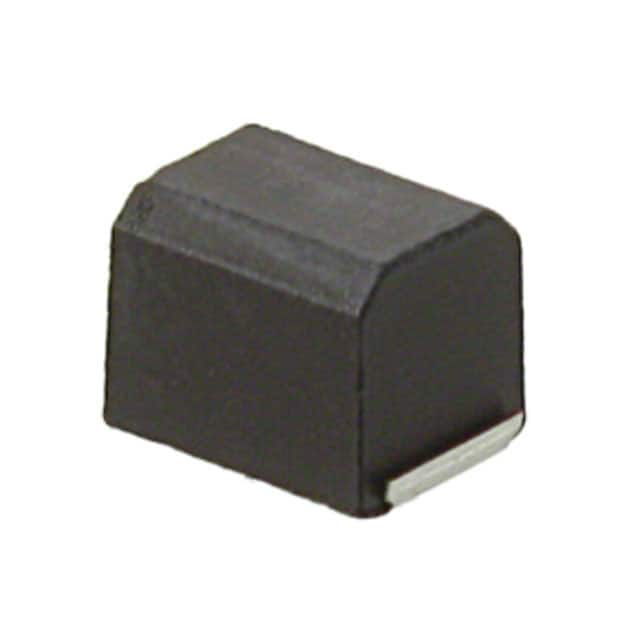
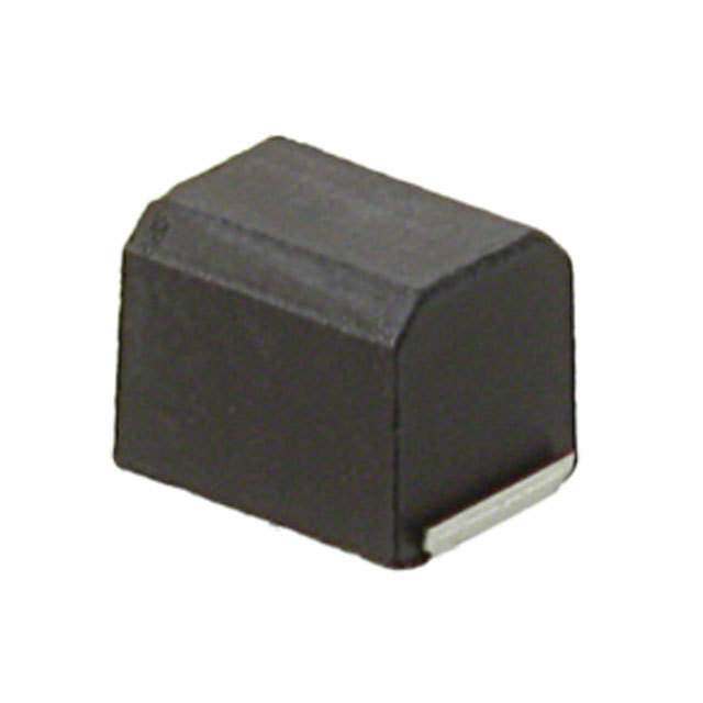
ICGOO电子元器件商城为您提供NLFC453232T-331K-PF由TDK设计生产,在icgoo商城现货销售,并且可以通过原厂、代理商等渠道进行代购。 NLFC453232T-331K-PF价格参考¥2.36-¥4.94。TDKNLFC453232T-331K-PF封装/规格:固定值电感器, 330µH 屏蔽 绕线 电感器 45mA 6 欧姆 1812(4532 公制) 。您可以下载NLFC453232T-331K-PF参考资料、Datasheet数据手册功能说明书,资料中有NLFC453232T-331K-PF 详细功能的应用电路图电压和使用方法及教程。
| 参数 | 数值 |
| 产品目录 | |
| DC电阻(DCR) | 6 欧姆 |
| 描述 | INDUCTOR SHIELD 330UH 10% 1812固定电感器 330uH |
| 产品分类 | |
| 品牌 | TDK Corporation |
| 产品手册 | |
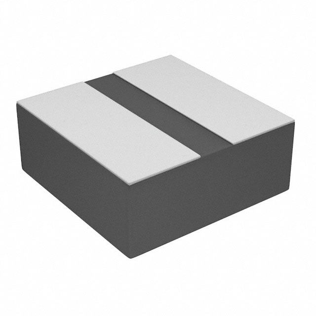
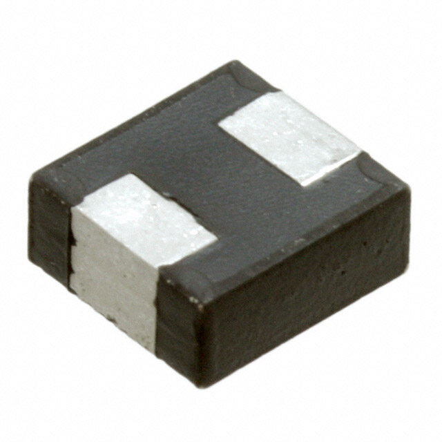
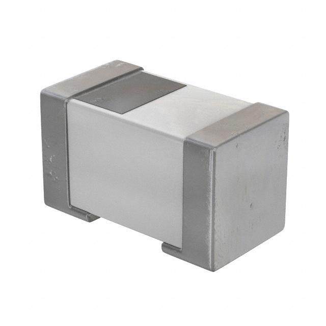
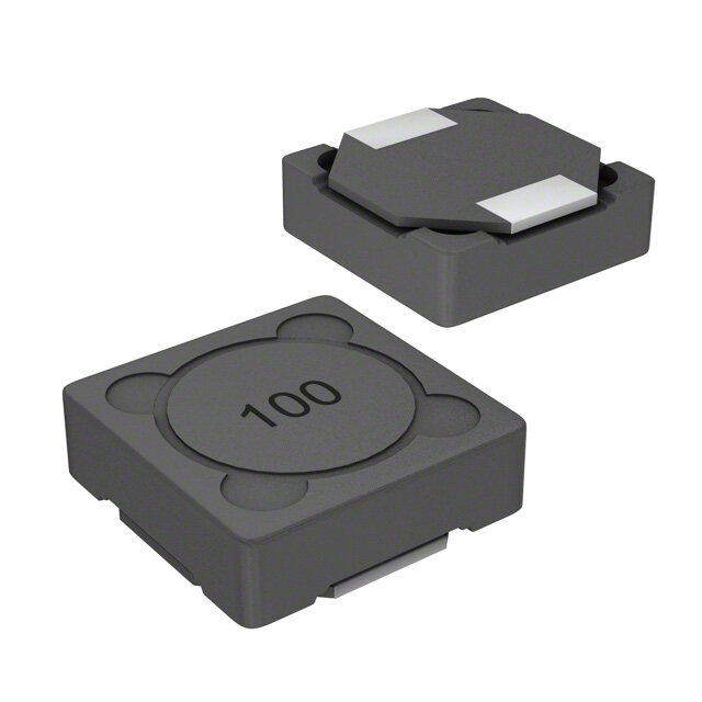
| 产品图片 |
|
| rohs | 符合RoHS无铅 / 符合限制有害物质指令(RoHS)规范要求 |
| 产品系列 | 固定电感器,TDK NLFC453232T-331K-PFNLFC |
| 数据手册 | |
| 产品型号 | NLFC453232T-331K-PF |
| Q最小值 | 10 |
| 不同频率时的Q值 | 10 @ 796kHz |
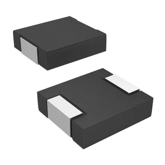
| 产品目录绘图 |
|
| 产品种类 | 固定电感器 |
| 供应商器件封装 | 1812 |
| 其它名称 | 445-6470-6 |
| 包装 | Digi-Reel® |
| 商标 | TDK |
| 外壳宽度 | 3.2 mm |
| 外壳长度 | 4.5 mm |
| 外壳高度 | 3.2 mm |
| 大小/尺寸 | 0.177" 长 x 0.126" 宽(4.50mm x 3.20mm) |
| 安装类型 | 表面贴装 |
| 容差 | ±10% |
| 封装 | Reel |
| 封装/外壳 | 1812(4532 公制) |
| 封装/箱体 | 4532 (1812 metric) |
| 屏蔽 | 屏蔽 |
| 工作温度 | -40°C ~ 105°C |
| 工作温度范围 | - 40 C to + 105 C |
| 工厂包装数量 | 500 |
| 最大直流电流 | 45 mA |
| 最大直流电阻 | 6 Ohms |
| 材料-磁芯 | - |
| 标准包装 | 1 |
| 测试频率 | 0.796 MHz |
| 电感 | 330µH |
| 电流-饱和值 | - |
| 端接类型 | SMD/SMT |
| 类型 | 绕线 |
| 系列 | NLFC |
| 自谐振频率 | 4 MHz |
| 频率-测试 | 796kHz |
| 频率-自谐振 | 4MHz |
| 额定电流 | 45mA |
| 高度-安装(最大值) | 0.134"(3.40mm) |




- 商务部:美国ITC正式对集成电路等产品启动337调查
- 曝三星4nm工艺存在良率问题 高通将骁龙8 Gen1或转产台积电
- 太阳诱电将投资9.5亿元在常州建新厂生产MLCC 预计2023年完工
- 英特尔发布欧洲新工厂建设计划 深化IDM 2.0 战略
- 台积电先进制程称霸业界 有大客户加持明年业绩稳了
- 达到5530亿美元!SIA预计今年全球半导体销售额将创下新高
- 英特尔拟将自动驾驶子公司Mobileye上市 估值或超500亿美元
- 三星加码芯片和SET,合并消费电子和移动部门,撤换高东真等 CEO
- 三星电子宣布重大人事变动 还合并消费电子和移动部门
- 海关总署:前11个月进口集成电路产品价值2.52万亿元 增长14.8%
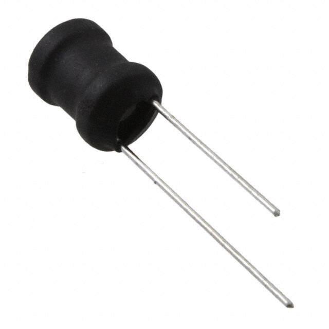
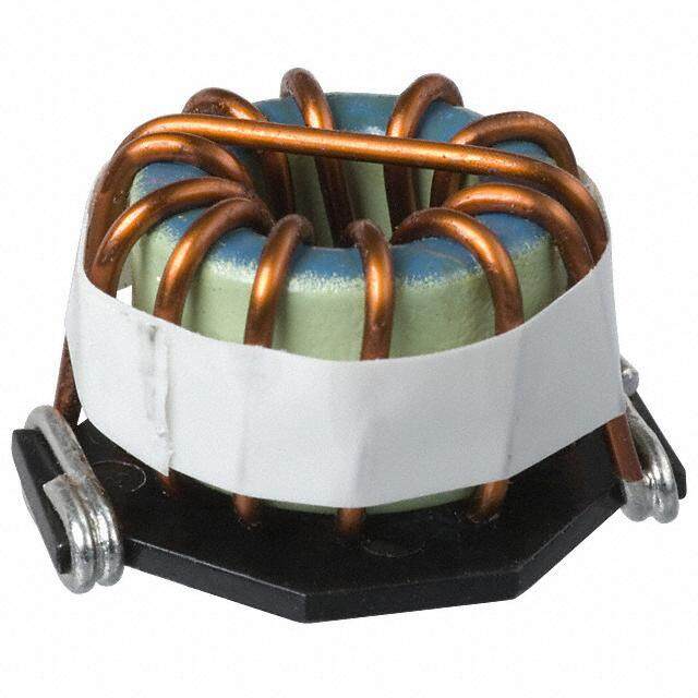
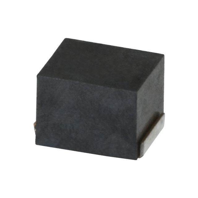
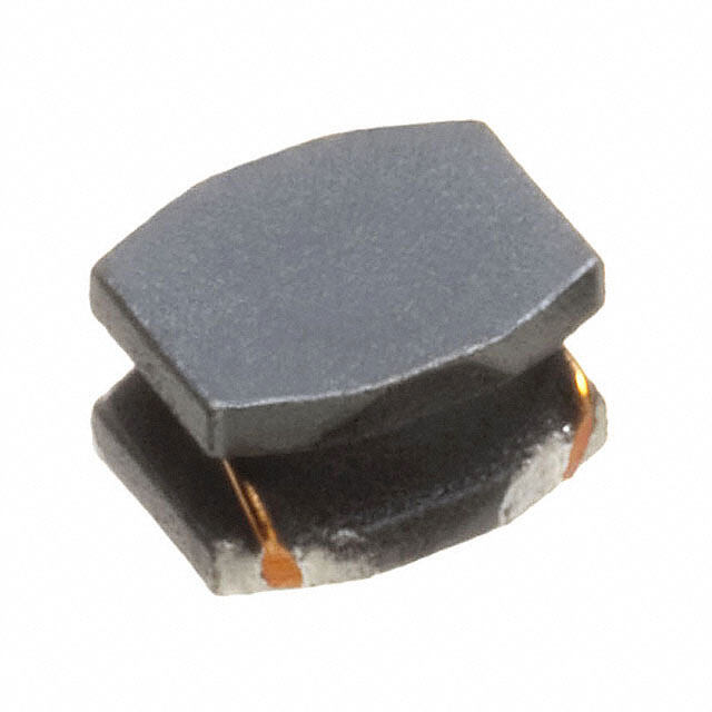

PDF Datasheet 数据手册内容提取
(1/2) SMD Inductors(Coils) Conformity to RoHS Directive For Power Line(Wound, Magnetic Shielded) NLFC Series NLFC453232 FEATURES IRON SOLDERING (cid:129) The NLFC series features magnetic shielding and is recom- Tip temperature 300 to 350°C mended for power supply line applications. Heating time 3 seconds/soldering Soldering rod specifications Output: 30W Tip diameter: 1mm (cid:129) The product has good heat durability that withstands lead-free (cid:129) Based on the above conditions, use a maximum product temperature of compatible reflow soldering conditions. 260°C and a maximum accumulated heating time of 10 seconds as a (cid:129) Lead-free material is used for the plating on the terminal. guideline. (cid:129) The product uses metal terminals, which realize excellent con- (cid:129) Please contact us for details. nection reliability. PRODUCT IDENTIFICATION (cid:129) From 1µH to 330µH, all of the products are available in the E-6 NLFC 453232 T- 2R2 M - PF series. (1) (2) (3) (4) (5) (6) (cid:129) It is a product conforming to RoHS directive. (1)Series name APPLICATIONS (cid:129) Electronic equipment used in communication infrastructures (2)Dimensions including xDSL and mobile base stations. 453232 4.5×3.2×3.2mm (L×W×T) (cid:129) Audio-visual equipment including TVs and VCRs. (cid:129) Other electronic equipment including HDDs and ODDs. (3)Packaging style SPECIFICATIONS T Taping (reel) –40 to +105°C Operating temperature range [Including self-temperature rise] (4)Inductance value Storage temperature range –40 to +105°C 1R0 1µH 100 10µH RECOMMENDED SOLDERING CONDITIONS 101 100µH REFLOW SOLDERING (5)Inductance tolerance 10s max. K ±10% 255˚C M ±20% 230˚C Natural cooling (6) Lead-free compatible product 180˚C PF Lead-free compatible product 150˚C Pre-heating PACKAGING STYLE AND QUANTITIES 90 to 120s 40s max. Packaging style Quantity Taping 500 pieces/reel Time(s) FLOW SOLDERING 10s max. 260˚C max. Natural cooling 170˚C 150˚C Pre-heating 60 to 120s Time(s) (cid:129) Conformity to RoHS Directive: This means that, in conformity with EU Directive 2002/95/EC, lead, cadmium, mercury, hexavalent chromium, and specific bromine-based flame retardants, PBB and PBDE, have not been used, except for exempted applications. • All specifications are subject to change without notice. 003-02 / 20090706 / e531_nlfc4532.fm
(2/2) SHAPES AND DIMENSIONS/RECOMMENDED PC BOARD PATTERN Inductor 100 Solder land pattern 4.5±0.3 3.2±0.2 C0.5 8 2. Terminal 2 electrode 5 0. R0.2 0. ± 1.5 3 1.5 2 3. (0.6) 2.6±0.1 Weight: 180mg Dimensions in mm ELECTRICAL CHARACTERISTICS Inductance Inductance Q Test frequency Self-resonant frequency DC resistance Rated current∗ Part No. (µH) tolerance ref. L, Q (MHz) (MHz)min. (Ω)±30% (mA)max. 1 ±20% 10 7.96 200 0.05 800 NLFC453232T-1R0M-PF 1.5 ±20% 10 7.96 130 0.06 700 NLFC453232T-1R5M-PF 2.2 ±20% 10 7.96 80 0.07 600 NLFC453232T-2R2M-PF 3.3 ±20% 10 7.96 45 0.09 460 NLFC453232T-3R3M-PF 4.7 ±20% 10 7.96 35 0.1 400 NLFC453232T-4R7M-PF 6.8 ±20% 10 7.96 28 0.14 300 NLFC453232T-6R8M-PF 10 ±10% 10 2.52 22 0.21 250 NLFC453232T-100K-PF 15 ±10% 10 2.52 20 0.3 200 NLFC453232T-150K-PF 22 ±10% 10 2.52 18 0.46 170 NLFC453232T-220K-PF 33 ±10% 10 2.52 14 0.63 140 NLFC453232T-330K-PF 47 ±10% 10 2.52 11.5 0.85 120 NLFC453232T-470K-PF 68 ±10% 10 2.52 10 1.2 100 NLFC453232T-680K-PF 100 ±10% 10 0.796 8 1.7 90 NLFC453232T-101K-PF 150 ±10% 10 0.796 7 2.3 65 NLFC453232T-151K-PF 220 ±10% 10 0.796 5.5 3.8 55 NLFC453232T-221K-PF 330 ±10% 10 0.796 4 6 45 NLFC453232T-331K-PF ∗ Rated current: Value obtained when current flows and the temperature has risen to 20°C or when DC current flows and the initial value of inductance has fallen by 10%, whichever is smaller. (cid:129) Test equipment L, Q: YHP4194A IMPEDANCE ANALYZER+YHP16085A+YHP16093B+TF-1, or equivalent SRF:HP8753C NETWORK ANALYZER (Zin=Zout=50Ω), or equivalent Rdc:MATSUSHITA VP-2941A DIGITAL MILLIOHM METER, or equivalent TYPICAL ELECTRICAL CHARACTERISTICS INDUCTANCE CHANGE vs. DC SUPERPOSITION IMPEDANCE vs. FREQUENCY CHARACTERISTICS CHARACTERISTICS 1030000 330μH Test ciDrCcuitAYSHpeLPc= mim5HoedneCl-=42207050A0μFUniversalbridge 100 3301μ0H0μH or equivalent 30 100μH 47μH 100 10 47μH 10μH μ()InductanceH 13003 140.7μμHH Ω()Impedancek 13 4.7μH 0.3 1μH 1μH 1 0.1 0.3 0.03 0.1 10 30 100 300 1000 3000 10000 0.01 DC current(mA) 0.1 0.3 1 3 10 30 100 Frequency(MHz) (cid:129) All specifications are subject to change without notice. 003-02 / 20090706 / e531_nlfc4532.fm
 Datasheet下载
