ICGOO在线商城 > MTE1S0509MC

 Datasheet下载
- 型号: MTE1S0509MC
- 制造商: Murata
- 库位|库存: xxxx|xxxx
- 要求:
| 数量阶梯 | 香港交货 | 国内含税 |
| +xxxx | $xxxx | ¥xxxx |
查看当月历史价格
查看今年历史价格
MTE1S0509MC产品简介:
ICGOO电子元器件商城为您提供MTE1S0509MC由Murata设计生产,在icgoo商城现货销售,并且可以通过原厂、代理商等渠道进行代购。 提供MTE1S0509MC价格参考¥39.18-¥49.82以及MurataMTE1S0509MC封装/规格参数等产品信息。 你可以下载MTE1S0509MC参考资料、Datasheet数据手册功能说明书, 资料中有MTE1S0509MC详细功能的应用电路图电压和使用方法及教程。
| 参数 | 数值 |
| 产品目录 | |
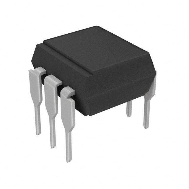
| 描述 | DC/DC CONVERTER 9V 111MA 1W隔离式DC/DC转换器 1W 5Vin 9Vout 111mA Single SM |
| 产品分类 | DC DC ConvertersDC/DC转换器 |
| 品牌 | Murata Power Solutions |
| 产品手册 | |
| 产品图片 |
|
| rohs | 符合RoHS无铅 / 符合限制有害物质指令(RoHS)规范要求 |
| 产品系列 | 隔离式DC/DC转换器,Murata Power Solutions MTE1S0509MCMTE1 |
| 数据手册 | |
| 产品型号 | MTE1S0509MC |
| 产品 | Isolated |
| 产品种类 | 隔离式DC/DC转换器 |
| 其它名称 | 811-2837-5 |
| 功率(W)-制造系列 | 1W |
| 功率(W)-最大值 | 1W |
| 包装 | 管件 |
| 商标 | Murata Power Solutions |
| 大小/尺寸 | 0.50" 长 x 0.42" 宽 x 0.28" 高(12.8mm x 10.7mm x 7.0mm) |
| 安装类型 | 表面贴装 |
| 安装风格 | SMD/SMT |
| 宽度 | 0.433 in |
| 封装 | Tube |
| 封装/外壳 | 8-SMD 模块 |
| 封装/箱体尺寸 | 12.7 mm x 11 mm x 7.05 mm |
| 尺寸 | 0.5 in x 0.433 in x 0.278 in |
| 工作温度 | -40°C ~ 85°C |
| 工作温度范围 | - 40 C to + 85 C |
| 工厂包装数量 | 30 |
| 效率 | 85% |
| 标准包装 | 30 |
| 特性 | - |
| 特色产品 | http://www.digikey.cn/product-highlights/zh/mte1-series-isolated-1-w-singleoutput-sm-dcdc-converters/52247 |
| 电压-输入(最大值) | 5.5V |
| 电压-输入(最小值) | 4.5V |
| 电压-输出1 | 9V |
| 电压-输出2 | - |
| 电压-输出3 | - |
| 电压-隔离 | 1kV(1000V) |
| 电流-输出(最大值) | 111mA |
| 类型 | 隔离模块 |
| 系列 | MTE1 |
| 绝缘电压 | 1 kV |
| 输入电压—公称值 | 5 V |
| 输入电压范围 | 4.5 V to 5.5 V |
| 输出功率 | 1 W |
| 输出数 | 1 |
| 输出电压—通道1 | 9 V |
| 输出电流—通道1 | 111 mA |
| 输出端数量 | 1 |
| 输出类型 | Single Isolated |
| 长度 | 0.5 in |
| 高度 | 0.278 in |


- 商务部:美国ITC正式对集成电路等产品启动337调查
- 曝三星4nm工艺存在良率问题 高通将骁龙8 Gen1或转产台积电
- 太阳诱电将投资9.5亿元在常州建新厂生产MLCC 预计2023年完工
- 英特尔发布欧洲新工厂建设计划 深化IDM 2.0 战略
- 台积电先进制程称霸业界 有大客户加持明年业绩稳了
- 达到5530亿美元!SIA预计今年全球半导体销售额将创下新高
- 英特尔拟将自动驾驶子公司Mobileye上市 估值或超500亿美元
- 三星加码芯片和SET,合并消费电子和移动部门,撤换高东真等 CEO
- 三星电子宣布重大人事变动 还合并消费电子和移动部门
- 海关总署:前11个月进口集成电路产品价值2.52万亿元 增长14.8%


PDF Datasheet 数据手册内容提取
MTE1 Series www.murata-ps.com Isolated 1W Single Output SM DC/DC Converters SELECTION GUIDE Order Code1 Nominal Input Voltage Output Voltage Output Current Input Current at Rated Load (Typ.) Load Regulation (Typ. ) Load Regulation (Max) Output Ripple & Noise (Typ.) Efficiency (Min.) Efficiency (Typ.) Isolation Capacitance 2MTTF V V mA mA % % mVp-p % % pF kHrs MTE1S0303MC 3.3 3.3 303 382 11 13.5 33 75 78 15 FEATURES MTE1S0305MC 3.3 5 200 363 8.5 11 24 79 82 16 n Single isolated output MTE1S0309MC 3.3 9 111 353 7 9 17 82 85 21 MTE1S0312MC 3.3 12 83 348 6.5 8 15 83 86 20 n 1kVDC Isolation MTE1S0315MC 3.3 15 66 346 6 8 13 83 86 20 MTE1S0503MC 5 3.3 303 248 9 12 24 77 79 21 n Efficiency up to 88% MTE1S0505MC 5 5 200 239 6.5 8 20 79 82 22 n Power density 1.8W/cm3 MTE1S0506MC 5 6 TBC 236 6 7.5 20 81 83 24 MTE1S0509MC 5 9 111 233 5 6.5 15 83 85 26 n Wide temperature performance at full MTE1S0512MC 5 12 83 227 5 6.5 14 84 87 29 1 Watt load, –40°C to 85°C MTE1S0515MC 5 15 66 225 5 6.5 11 85 88 33 MTE1S1205MC 12 5 200 97 5 7 19 81 84 34 n UL 94V-0 Package material MTE1S1209MC 12 9 111 95 3 4.5 13 82 86 39 MTE1S1212MC 12 12 83 93 3 4.5 12 85 88 43 n Footprint over pins 1.37cm2 MTE1S1215MC 12 15 66 93 3 4 11 85 88 40 n 3.3V, 5V, 12V, 15V & 24V Input MTE1S1505MC 15 5 200 79 4 5.5 15 80 83 25 MTE1S1509MC 15 9 111 77 3 4 9 81 86 38 n 3.3V, 5V, 9V, 12V & 15V Output MTE1S1512MC 15 12 83 76 2.5 4 10 82 87 45 MTE1S1515MC 15 15 66 75 2.5 4 8 84 88 57 n Internal SMD construction MTE1S2405MC 24 5 200 50 4 5.5 20 79 83 21 n Toroidal magnetics MTE1S2409MC 24 9 111 48 2.5 4 19 84 86 31 MTE1S2412MC 24 12 83 48 2 3.5 19 83 87 41 MTE1S2415MC 24 15 66 48 2 3.5 22 85 88 48 PRODUCT OVERVIEW INPUT CHARACTERISTICS The MTE1 series is a new range of surface mount, Parameter Conditions Min. Typ. Max. Units high performance 1W DC-DC converters. The Continuous operation, 3.3V input types 2.97 3.3 3.63 MTE1 series is the new high performance version Continuous operation, 5V input types 4.5 5.0 5.5 of our 1W NTE series, the MTE1 series is more Voltage range Continuous operation, 12V input types 10.8 12.0 13.2 V efficient and offers improved regulation perfor- Continuous operation, 15V input types 13.5 15.0 16.5 mance. The MTE1 series offers 1W of available Continuous operation, 24V input types 21.6 24 26.4 output power over the full industrial temperature Reflected ripple current 5 15 mA p-p range of -40ºC to 85ºC. ISOLATION CHARACTERISTICS The MTE1 series has a MSL rating 1, and is Parameter Conditions Min. Typ. Max. Units compatible with a peak reflow solder temperature Isolation voltage Flash tested for 1 second 1000 VDC of 245˚C as per J-STD-020D. Resistance Viso= 1000VDC 20 GΩ GENERAL CHARACTERISTICS Parameter Conditions Min. Typ. Max. Units Switching frequency All output types 80 Hz ABSOLUTE MAXIMUM RATINGS Lead temperature 1.5mm from case for 10 seconds 300°C Internal power dissipation 600mW Input voltage VIN, MTE03 types 5.5V Input voltage VIN, MTE05 types 7V Input voltage VIN, MTE12 types 15V Input voltage VIN, MTE15 types 18V Input voltage VIN, MTE24 types 28V 1. If components are required in tape and reel format suffix order code with -R, e.g. MTE0505MC-R. 2. Calculated using MIL-HDBK-217 FN2 calculation model with nominal input voltage at full load. For full details go to www.murata-ps.com/rohs All specifications typical at TA=25°C, nominal input voltage and rated output current unless otherwise specified. www.murata-ps.com All enquiries: www.murata-ps.com/support KDC_MTE1.A01_D4 Page 1 of 7
MTE1 Series Isolated 1W Single Output SM DC/DC Converters OUTPUT CHARACTERISTICS Parameter Conditions Min. Typ. Max. Units Rated power TA=-40°C to 85°C 1.0 W Voltage set point accuracy See tolerance envelope Line regulation High VIN to low VIN 1.1 1.2 %/% Ripple and noise BW=DC to 20MHz 25 70 mV p-p TEMPERATURE CHARACTERISTICS Parameter Conditions Min. Typ. Max. Units Specification All output types -40 85 Storage -50 130 °C Case temperature rise above ambient All output types 12.5 20 Cooling Free air convection TECHNICAL NOTES ISOLATION VOLTAGE ‘Hi Pot Test’, ‘Flash Tested’, ‘Withstand Voltage’, ‘Proof Voltage’, ‘Dielectric Withstand Voltage’ & ‘Isolation Test Voltage’ are all terms that relate to the same thing, a test voltage, applied for a specified time, across a component designed to provide electrical isolation, to verify the integrity of that isolation. Murata Power Solutions MTE series of DC/DC converters are all 100% production tested at their stated isolation voltage. This is 1kVDC for 1 second. A question commonly asked is, “What is the continuous voltage that can be applied across the part in normal operation?” For a part holding no specific agency approvals, such as the MTE series, both input and output should normally be maintained within SELV limits i.e. less than 42.4V peak, or 60VDC. The isolation test voltage represents a measure of immunity to transient voltages and the part should never be used as an element of a safety isolation system. The part could be expected to function correctly with several hundred volts offset applied continuously across the isolation barrier; but then the circuitry on both sides of the barrier must be regarded as operating at an unsafe voltage and further isolation/insulation systems must form a barrier between these circuits and any user-accessible circuitry according to safety standard requirements. REPEATED HIGH-VOLTAGE ISOLATION TESTING It is well known that repeated high-voltage isolation testing of a barrier component can actually degrade isolation capability, to a lesser or greater degree depending on materials, construction and environment. The MTE series has toroidal isolation transformers, with no additional insulation between primary and secondary windings of enameled wire. While parts can be expected to withstand several times the stated test voltage, the isolation capability does depend on the wire insulation. Any material, including this enamel (typically polyurethane) is susceptible to eventual chemical degradation when subject to very high applied voltages thus implying that the number of tests should be strictly limited. We therefore strongly advise against repeated high voltage isolation testing, but if it is absolutely required, that the voltage be reduced by 20% from specified test voltage. This consideration equally applies to agency recognized parts rated for better than functional isolation where the wire enamel insulation is always supplemeMTEd by a further insulation system of physical spacing or barriers. TEMPERATURE DERATING GRAPH 1.5 er (W)1.0 85°C w o P ut 0.5 Safe Operating Area p ut O 0 -40 0 50 100 150 Ambient Temperature (°C) 1. 12V input types have typically 3% less load regulation change. www.murata-ps.com All enquiries: www.murata-ps.com/support KDC_MTE1.A01_D4 Page 2 of 7
MTE1 Series Isolated 1W Single Output SM DC/DC Converters TOLERANCE ENVELOPES The voltage tolerance envelope shows typical load regulation characteristics for this product series. The tolerance envelope is the maximum output voltage variation due to changes in output loading. 0303, 0503 0305,0309 +12% +8% +5% +8% ge Output Volta +3% utput Voltage +2% O -4% -4% 10 25 50 75 100 10 25 50 75 100 Output Load Current (%) Output Load Current (%) 0312, 0315, 0505, 0506, 0509 1209, 1212, 1505 +4% +6% +4% ge Output Volta +2% utput Voltage 0% +1% O -3% -4% 10 25 50 75 100 10 25 50 75 100 Output Load Current (%) Output Load Current (%) 0512, 0515, 1205,2405 1215, 1509, 1512, 1515, 2409, 2412, 2415 +5% +3% +2% Output +1% Output Voltage 0% +-21%% -4% 10 25 50 75 100 10 25 50 75 100 Output Load Current (%) Output Load Current (%) www.murata-ps.com All enquiries: www.murata-ps.com/support KDC_MTE1.A01_D4 Page 3 of 7
MTE1 Series Isolated 1W Single Output SM DC/DC Converters EFFICIENCY VS LOAD 3.3V Input 5V Input 90 90 70 70 Efficiency (%) 5300 MMMTTTEEE111SSS000333000359MMMCCC MMMMMTTTTTEEEEE11111SSSSS00000333330001135925MMMMMCCCCCEfficiency (%) 5300 MMMMTTTTEEEE1111SSSS0000555500013592MMMMCCCC MMMMMMTTTTTTEEEEEE111111SSSSSS000000555555000110359256MMMMMMCCCCCC MTE1S0312MC MTE1S0515MC 10 MTE1S0315MC 10 MTE1S0506MC 0 20 40 60 80 100 0 20 40 60 80 100 Load (%) Load (%) 12V Input 15V Input 90 90 70 70 Efficiency (%) 5300 MMTTEE11SS11220059MMCC MMMMTTTTEEEE1111SSSS1111222200115925MMMMCCCCEfficiency (%) 5300 MMTTEE11SS11550059MMCC MMMMTTTTEEEE1111SSSS1111555500115925MMMMCCCC MTE1S1212MC MTE1S1512MC 10 MTE1S1215MC 10 MTE1S1515MC 0 20 40 60 80 100 0 20 40 60 80 100 Load (%) Load (%) 24V Input 90 70 ency (%) 50 MMMTTTEEE111SSS222444001592MMMCCC Effici 30 MMTTEE11SS22440059MMCC MTE1S2415MC MTE1S2412MC MTE1S2415MC 10 0 20 40 60 80 100 Load (%) RoHS COMPLIANCE, MSL AND PSL INFORMATION This series is compatible with RoHS soldering systems with a peak reflow solder temperature of 245ºC as per J-STD-020D. The pin termination finish on this product series is Matte Tin over Nickel Preplate. The series is backward compatible with Sn/Pb soldering systems. The series has a Moisture Sensitivity Level (MSL) 1. Samples of the product series were tested in accordance with the conditioning described for MSL level 1 in IPS/J-STD-020D. The product series passed electrical tests and visual inspection criteria. For further information, please visit: www.murata-ps.com/rohs www.murata-ps.com All enquiries: www.murata-ps.com/support KDC_MTE1.A01_D4 Page 4 of 7
MTE1 Series Isolated 1W Single Output SM DC/DC Converters APPLICATION NOTES Minimum load The minimum load to meet datasheet specification is 10% of the full rated load across the specified input voltage range. Lower than 10% minimum loading will result in an increase in output voltage, which may rise to typically double the specified output voltage if the output load falls to less than 5%. Capacitive loading and start up Typical start up times for this series, with a typical input voltage rise time of 2.2µs and output capacitance of 10µF, are shown in the table below. The product series will start into a capacitance of 47µF with an increased start time, however, the maximum recommended output capacitance is 10µF. Start-up time Start-up time Start-up time µs µs µs MTE1S0303MC MTE1S0509MC MTE1S1509MC MTE1S0305MC MTE1S0512MC MTE1S1512MC MTE1S0309MC MTE1S0515MC MTE1S1515MC MTE1S0312MC MTE1S1205MC MTE1S2405MC MTE1S0315MC MTE1S1209MC MTE1S2409MC MTE1S0503MC MTE1S1212MC MTE1S2412MC MTE1S0505MC MTE1S1215MC MTE1S2415MC MTE1S0506MC MTE1S1505MC Output Ripple Reduction By using the values of inductance and capacitance stated, the output ripple at the rated load is lowered to 5mV p-p max. Component selection Capacitor: It is required that the ESR (Equivalent Series Resistance) should be as low as possible, ceramic types are recommended. The voltage rating should be at least twice (except for 15V output), the rated output voltage of the DC/DC converter. Inductor: The rated current of the inductor should not be less than that of the output of the DC/DC converter. At the rated current, the DC resistance of the inductor should be such that the voltage drop across the inductor is <2% of the rated voltage of the DC/DC converter. The SRF (Self Resonant Frequency) should be >20MHz. L DC Power Typical Start-Up Wave Form Source C Load DC Inductor Capacitor Inductor Capacitor L, µH SMD Through Hole C, µF L, µH SMD Through Hole C, µF MTE1S0303MC MTE1S1209MC MTE1S0305MC MTE1S1212MC MTE1S0309MC MTE1S1215MC MTE1S0312MC MTE1S1505MC MTE1S0315MC MTE1S1509MC MTE1S0503MC MTE1S1512MC MTE1S0505MC MTE1S1515MC MTE1S0506MC MTE1S2405MC MTE1S0509MC MTE1S2409MC MTE1S0512MC MTE1S2412MC MTE1S0515MC MTE1S2415MC MTE1S1205MC www.murata-ps.com All enquiries: www.murata-ps.com/support KDC_MTE1.A01_D4 Page 5 of 7
MTE1 Series Isolated 1W Single Output SM DC/DC Converters PACKAGE SPECIFICATIONS MTE1S0303MC XYYWW MECHANICAL DIMENSIONS PIN CONNECTIONS 12.70±0.20 [0.500±0.008] Pin Function 7.62 [0.300] 1 -VIN MTE1S0303MC 3 +VIN 5 NA 11.00±0.15 [0.433±0.006] XYYWW 7 -VOUT 10.70±0.15 [0.421±0.006] 8 +VOUT 10 NA 12 NA 2.54 [0.100] 14 NA 7.05 +-00.1.305 [0.278+-00..000144] SS 0.25±0.05 [0.010±0.002] NA - Not available for electrical connection. 0.2 MIN SEATING PLANE 2.54±0.15 [0.100±0.006] 1.56±0.10 [0.061±0.004] x5 PINS 0.10 S All dimensions in mm ±0.25mm (inches ±0.01). All pins on a 2.54 (0.1) pitch and within ± 0.25 (0.01) of true position. Weight: 1.1g RECOMMENDED FOOTPRINT DETAILS TUBE OUTLINE DIMENSIONS 7.62 (0.3) 2.00 (0.079) 0.60±0.15 (0.024±0.006) 2.10 (0.083) 9.70 (0.382) 14.35 (0.565) 9.40 (0.370) 2.54 (0.1) 1.00 (0.040) MIN All pins on a 2.54mm pitch. Unless otherwise stated all dimensions in mm±60.7.05 m(0m.2 6(i4n)ches ±0.02). Unless otherwise stated all dimensions in mm (inches) ±0.5mm. Tube length : 475±2.0 (18.70±0.07). Tube Quantity : 35 www.murata-ps.com All enquiries: www.murata-ps.com/support KDC_MTE1.A01_D4 Page 6 of 7
MTE1 Series Isolated 1W Single Output SM DC/DC Converters TAPE & REEL SPECIFICATIONS REEL OUTLINE DIMENSIONS TAPE OUTLINE DIMENSIONS 13.20 (0.52) 0.60 (0.02) MAX 100 Ø (3.94) MIN +0.004 (+0.10) 1.50 (Ø0.06) -0.00 (-0.00) G N (AT HUB SECTION) Ø 1(03..5010±±00..02059) (20..0008 ) DIRECTION OF UNREELI 16.00 (0.63) 11.60 (0.46) 4.00 (0.16) 1.75(0.07) 6.60 11.50 (0.26) (0.45) 24.00±0.30 (0.94±0.04) REEL PACKAGING DETAILS XYYWWMTE1S0303MC XYYWWMTE1S0303MC XYYWWMTE1S0303MC TRAILER SECTION GOODS ENCLOSURE CARRIER TAPE START 160 (6.30) MIN SECTION 100 (3.94) MIN Product Orientation Pin 1, located nearest to LEADER SECTION carrier drive sprocket. 400 (15.75) MIN Reel Quantity : TBC Murata Power Solutions, Inc. Murata Power Solutions, Inc. makes no representation that the use of its products in the circuits described herein, or the use of other 11 Cabot Boulevard, Mansfield, MA 02048-1151 U.S.A. technical information contained herein, will not infringe upon existing or future patent rights. The descriptions contained herein do not imply the granting of licenses to make, use, or sell equipment constructed in accordance therewith. Specifications are subject to change without ISO 9001 and 14001 REGISTERED notice. © 2012 Murata Power Solutions, Inc. www.murata-ps.com/locations All enquiries: www.murata-ps.com/support KDC_MTE1.A01_D4 Page 7 of 7
Mouser Electronics Authorized Distributor Click to View Pricing, Inventory, Delivery & Lifecycle Information: M urata: MTE1S0505MC-R MTE1S0303MC-R MTE1S0512MC MTE1S0515MC-R MTE1S0305MC-R MTE1S2415MC-R MTE1S2405MC-R MTE1S1212MC MTE1S1212MC-R MTE1S2415MC MTE1S1512MC MTE1S1505MC MTE1S1509MC-R MTE1S0315MC-R MTE1S1512MC-R MTE1S0303MC MTE1S0509MC MTE1S0506MC-R MTE1S1215MC MTE1S2409MC-R MTE1S0506MC MTE1S1209MC MTE1S1509MC MTE1S2412MC MTE1S0312MC MTE1S1215MC-R MTE1S1205MC-R MTE1S0315MC MTE1S0309MC-R MTE1S1515MC MTE1S0309MC MTE1S0503MC-R MTE1S2409MC MTE1S1205MC MTE1S0503MC MTE1S1505MC-R MTE1S0312MC-R MTE1S0305MC MTE1S1515MC-R MTE1S2405MC MTE1S1209MC-R MTE1S0512MC-R MTE1S2412MC-R MTE1S0509MC-R MTE1S0515MC MTE1S0505MC