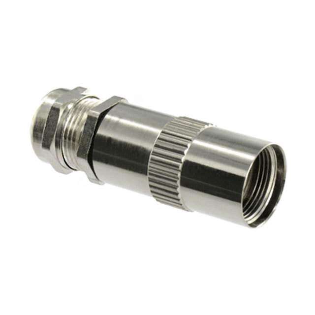
ICGOO在线商城 > MS3472L8-33A
- 型号: MS3472L8-33A
- 制造商: CORCOM/TYCO ELECTRONICS
- 库位|库存: xxxx|xxxx
- 要求:
| 数量阶梯 | 香港交货 | 国内含税 |
| +xxxx | $xxxx | ¥xxxx |
查看当月历史价格
查看今年历史价格
MS3472L8-33A产品简介:
ICGOO电子元器件商城为您提供MS3472L8-33A由CORCOM/TYCO ELECTRONICS设计生产,在icgoo商城现货销售,并且可以通过原厂、代理商等渠道进行代购。 提供MS3472L8-33A价格参考以及CORCOM/TYCO ELECTRONICSMS3472L8-33A封装/规格参数等产品信息。 你可以下载MS3472L8-33A参考资料、Datasheet数据手册功能说明书, 资料中有MS3472L8-33A详细功能的应用电路图电压和使用方法及教程。
| 参数 | 数值 |
| 产品目录 | |
| 描述 | CONN HSG RCPT FLANGE 3POS PIN |
| 产品分类 | |
| 品牌 | TE Connectivity |
| 数据手册 | |
| 产品图片 | |
| 产品型号 | MS3472L8-33A |
| rohs | 含铅 / 不符合限制有害物质指令(RoHS)规范要求 |
| 产品系列 | 军用, MIL-C-26482 G 系列 II, AFD |
| 侵入防护 | 抗环境影响 |
| 其它名称 | DMS3472L8-33A |
| 包装 | 散装 |
| 备注 | 不提供触点 |
| 外壳尺寸-插件 | 8-33 |
| 外壳尺寸,MIL | - |
| 外壳材料,镀层 | 铝,非电镀法镀镍 |
| 安装类型 | 面板安装,法兰 |
| 朝向 | N(正常型) |
| 标准包装 | 1 |
| 特性 | - |
| 紧固类型 | 插销锁 |
| 触头尺寸 | 20 |
| 触头类型 | 压接 |
| 连接器类型 | 公触点插座 |
| 针脚数 | 3 |





- 商务部:美国ITC正式对集成电路等产品启动337调查
- 曝三星4nm工艺存在良率问题 高通将骁龙8 Gen1或转产台积电
- 太阳诱电将投资9.5亿元在常州建新厂生产MLCC 预计2023年完工
- 英特尔发布欧洲新工厂建设计划 深化IDM 2.0 战略
- 台积电先进制程称霸业界 有大客户加持明年业绩稳了
- 达到5530亿美元!SIA预计今年全球半导体销售额将创下新高
- 英特尔拟将自动驾驶子公司Mobileye上市 估值或超500亿美元
- 三星加码芯片和SET,合并消费电子和移动部门,撤换高东真等 CEO
- 三星电子宣布重大人事变动 还合并消费电子和移动部门
- 海关总署:前11个月进口集成电路产品价值2.52万亿元 增长14.8%



PDF Datasheet 数据手册内容提取
Amphenol MIL-DTL-26482, Series 2, Matrix ® TABLE OF CONTENTS MIL-DTL-26482, Series 2, Matrix® • Design Characteristics, Customer Options . . . . . . . 333 • Insert Availability and Identification, Alternate Positioning . . . . . . . . . . . . . . . 334 • Insert Arrangement Drawings . . . . . . . . . . 335, 336 • Class Descriptions, Performance Specifications . . . . . 337 • How to Order (Military and Commercial). . . . . . . . 338 Shell Styles: • Wall Mounting Receptacle with Narrow Flange, Wall Mounting Receptacle with Wide Flange . . . . . . 339 • Cable Connecting Receptacle, Jam Nut Receptacle. . . . . . . . . . . . . . . . 340 • Straight Plug, Straight Plug with RFI Grounding Fingers . . . . . . . 341 Contacts and Tools: • Contact Information, Sealing Plugs, Crimping and Insertion/Removal Tools . . . . . . . . . . . . . . 342 • Assembly Instructions . . . . . . . . . . . . . 343, 344 Additional MIL-DTL-26482 Connectors • Brief Description of Commercial/Military MIL-DTL-26482, Series 1 . . . . . . . . . . . . . . . . . . . . 345 (Covered in-depth in Amphenol Industrial Catalog 12-070) MIL-DTL-26482 Series 2, Matrix® Typical Markets: • Military & Commercial Aviation - Cockpit, Landing Gear, Aircraft Frame Amphenol • Military Aircraft Carriers Aerospace • Instrumentation/Process Control/Test Equipment • C4ISR 332 Contact Amphenol Aerospace for more information at 800-678-0141 • www.amphenol-aerospace.com
Amphenol MIL-DTL-26482, Series 2, Matrix® Aerospace Bayonet Coupling Connectors With Crimp Rear Release Contacts 38999 III Amphenol Aerospace offers the Matrix® Product line of HD MIL-DTL-26482*, Series 2 connectors. Dualok This series provides a bayonet coupling connector with crimp rear insertable, rear releasable contacts. II I DESIGN CHARACTERISTICS • Medium size, environmentally resistant connector MS3470 SJT wall mounting receptacle Accessories • Recommended operating voltage to 1,000 VAC (RMS) at sea level with narrow flange Aquacon • Quick positive coupling assured by 3 point bayonet MS3472 Herm/Seal wall mounting receptacle coupling system PCB with wide flange • Visual confirmation of complete coupling • Eliminates mismating by the use of five key/keyway design HIgH SPEED • Insertion and removal of contacts from the rear of the con nector assures no damage to the front that might affect Fiber Optics the sealing characteristics • Utilizes same standard qualified rear-release type plastic Contacts tool for contact insertion and removal Connectors Cables • Contacts are qualified to SAE AS39029** requirements – BIN coded (three color bands), and are crimped with MS3471 TE standard crimp tools per MIL-DTL-22520 raM • Ganrodm exmpeetrsie anrcee c noon sdterugcratedda otiof tne warh-reens eisxtpaonst eedla tsoto am beror ad ctaacblele connecting recep- nsientI Filter range of fluids • Sealing over a range of wire diameters is assured by a M2 a6 tri ple webbed grommet at the rear of the connector trix48 • Closed entry socket side of the insert is designed with a 2 2 lead-in chamfer and a hard face that will accept a pin M8 con tact bent within pre-established limits atrix372 • Ebalarsrit eorms earr oinutnedrf aecaicahl speina lw ohni cthhe d pisipnl asicdee i nhtaos t rhaeis seodc k et MS3474 |Pyle3 III cham fer when mated, providing a positive moisture seal jam nut receptacle 2 CUSTOMER OPTIONS Py65 le0 • Shell styles within this family include: Wall mount with 0 either a narrow or a wide flange, jam nut single hole mount, and cable connecting receptacles, along with standard C • psMilzuSeg ass n 8od rt oPp lr2uo4gpsri ewtiathry R vFeIr sgiroonusn advinagil afibnl geers, in shell MatrixRelease rimp Rear5015 • Accommodation of contact sizes 20, 16 and 12 C2 • 34 insert arrangement patterns available, accommodating MS3476 lass299 from a minimum of 3 to a maximum of 55 circuits straight plug L 2 • Alternate positioning available MS3475 • Various finishes are available (for information on plug with RFI grounding SB non-cad mium zinc alloy plating, consult Amphenol fingers heac Aerospace) llsk- * MIL-DTL-26482 supersedes MIL-C-26482 OO ** SAE AS39029 supersedes MIL-C-39029 theptio rsns Contact Amphenol Aerospace for more information at 800-678-0141 • www.amphenol-aerospace.com 333
Amphenol MIL-DTL-26482, Series 2, Matrix® Aerospace Insert Availability and Identification Alternate Rotations 38999 III INSERT ARRANGEMENTS ALTERNATE ROTATIONS OF INSERT HD Dualok Insert Service Total Contact Size To avoid cross-plugging problems in applications requiring the II Arrangement Rating Contacts 12 16 20 use of more than one connector of the same size and arrangement, alternate rotations are available as indicated in 8-33 I 3 3 I the chart below. 8-98 I 3 3 SJT As shown in the diagram, the front face of the pin insert is rotated 10-6 I 6 6 Accessories within the shell in a clockwise direction from the normal shell 12-3 II 3 3 key. The socket insert would be rotated counter-clockwise the Aquacon 12-8 I 8 8 same number of degrees in respect to the normal shell key. Herm/Seal 12-10 I 10 10 PCB 14-4 I 4 4 HIgH 14-5 II 5 5 A A B B SPEED 14-9 I 9 4 5 B B A A 14-12 I 12 4 8 Fiber Optics 14-15 I 15 1 14 Position W Position X Position Y Position Z 14-18 I 18 18 Contacts View looking into front face of pin insert or rear of socket insert. Connectors 14-19 I 19 19 Cables 16-8 II 8 8 Degrees Insert 16-23S I 23 1 22 ernt Arrangement W X Y Z Filtsie 16-26 I 26 26 8-33 90 – – – MI an 18-8 I 8 8 8-98 – – – – ETr 18-11 II 11 11 10-6 90 – – – 18-30 I 30 1 29 12-3 – – 180 – 22 12-8 90 112 203 292 8x 18-32 I 32 32 64atri 20-16 II 16 16 12-10 60 155 270 295 2M 14-4 45 – – – 20-24S I 24 24 14-5 40 92 184 273 23 IIIx|Pyle 2200--4319 II 4319 2 4317 1144--192 1453 9900 18–0 27–0 837Matri 22-12 I 12 12 14-15 17 110 155 234 22-19S I 19 19 14-18 15 90 180 270 00 e 22-21 II 21 21 14-19 30 165 315 – 265Pyl 22-32S I 32 32 16-8 54 152 180 331 16-23 158 270 – – 22-41 I 41 14 27 16-26 60 – 275 338 22-55 I 55 55 5015Crimp RearRelease Matrix 2242--1995S III 1392 169 26 111888---13810 11688200 11–1993 22–4815 33–4500 24-31 I 31 31 18-32 85 138 222 265 2 L 24-61 I 61 61 20-16 238 318 333 347 9s 229Clas Arrangements designated with an S are tooled in socket only. 2200--2349 7603 114454 221552 239303 20-41 45 126 225 – 22-12 – – – – - s ckell 22-19 15 90 225 308 ah BS 22-21 16 135 175 349 22-32 72 145 215 288 Options Others 222222---459155 332906 111348520 222626466 3–1–4 24-19 30 165 315 – 24-31 90 225 255 – 24-61 90 180 270 324 334 Contact Amphenol Aerospace for more information at 800-678-0141 • www.amphenol-aerospace.com
Amphenol MIL-DTL-26482, Series 2, Matrix® Aerospace Insert Arrangements Front face of pin insert or rear face of socket insert illustrated 38999 A III C BA BC A EFD ACB C B A FEG HDACB G HFKEAJDB C D C B ED A CB HIDI Du a lok Insert Arrangement 8-33 8-98 10-06 12-03 12-08 12-10 14-04 14-05 I Service Rating I I I II I I I II SJT Accessories Number of Contacts 3 3 6 3 8 10 4 5 Aquacon Contact Size 20 20 20 16 20 20 12 16 Herm/Seal PCB GFH JAE BDC MGF EH JLAD CBK HJGRK L AMFP BNECD JHKTGMSL UF ANREPBDC KJLHUTMGNVAFPSBRECD F GE HA DB C FHSiPbIgeErE HD Optics Insert Arrangement 14-09 14-12 14-15 14-18 14-19 16-08 Contacts Connectors Service Rating I I I I I II Cables Number of Contacts 5 4 8 4 14 1 18 19 8 TE Contact Size 20 12 20 16 20 16 20 20 16 raM nsI F ienilte tr LKMJXWYN PVZR ASUTBECD MLNKZaPY RS cbXAT WBUVFCED FG HA BC GH J KLA BC NMPLbRacZdSg YAefTXBUWCVGDFE Matrix 2 26482 H G F J H G E D F E D K J H Ma83 trix72 Insert Arrangement 16-23 16-26 18-08 18-11 18-30 |Pyle3 III Service Rating I I I II I 2 Number of Contacts 22 1 26 8 11 29 1 P6 y5 le0 Contact Size 20 16 20 12 16 20 16 0 C NMPLcdRbKeSjaJhTUfHAZgVGYBWXFCED JHK GLSR MF PNAE BDC JHK VGULWaTFMXZ SYNAREPDBC RSPTNghUifM qjrVLe WpKkXAJdmnYBHcZbaGCDFE STRUhPgVifWNrjsqeMAXktLBdpmYKCncZJbDaHEGF MatrixRelease Class L rimp Rear22992 5015 Insert Arrangement 18-32 20-16 20-24 20-39 20-41 SB ha Service Rating I II I I I ellsck- Number of Contacts 32 16 24 37 2 41 Contact Size 20 16 20 20 16 20 OO theptio rsns NOTE: Connectors sold as mil-spec connectors will have mil-spec markings on the insert (a “snail-trail” designating the numerical path). Commercial versions will have insert markings as shown here. CONTACT LEGEND 20 16 12 Contact Amphenol Aerospace for more information at 800-678-0141 • www.amphenol-aerospace.com 335
Amphenol MIL-DTL-26482, Series 2, Matrix® Aerospace Insert Arrangements Front face of pin insert or rear face of socket insert illustrated 38999 III A M A N A N A HD J B L N B M P B M b P R B Dualok H M K C K U V P C L W X R C L Z a gh j cd S T C III G F L E D J H T S R D K J V U T S E D K JY X f e V UED SJT G E H F H W F F G G Accessories Insert Arrangement 22-12 22-19 22-21 22-32 Aquacon Herm/Seal Service Rating I I II I PCB Number of Contacts 12 19 21 32 Contact Size 12 12 16 20 HIgH SPEED Fiber Optics Contacts Connectors EMI Filter CTransientables UTVSWRXihjP YgksNr MmqZtf ALaenpBKbdcCJ DHEGF PNRMkij ShLmzy TgxKnGAFGFAUfwHBEHBEvVpeACDCDduqWJB tXsrcHCaYbZGDEF TSURVPWfgNhXeM dYiAL BKcZCaJbDHEGF K LJ MUH NT GAV SP RBF CE D 22 8x 64atri Insert Arrangement 22-41 22-55 22-95 24-19 2M Service Rating I I I II 23 IIIx|Pyle Number of Contacts 27 14 55 26 6 19 37atri Contact Size 20 16 20 20 12 12 8M 0 0e 5yl 6P 2 5015Crimp RearRelease Matrix KJ XYL MZef Nag APbc QRB DC VWXrsYt FZGuFGMaMNNvHPbHPJJwAKcKxdBy eCfgDEF 22992 Class L WH GV Ud TF SE UT SqRpEEDnDCmCLLBkB AjAziKhJ HG P N M L - s Insert Arrangement 24-31 24-61 ckell ah Service Rating I I BS Number of Contacts 31 61 ons ers Contact Size 16 20 OptiOth NOTE: Connectors sold as mil-spec connectors will have mil-spec markings on the insert (a “snail-trail” designating the numerical path). Commercial versions will have insert markings as shown here. CONTACT LEGEND 20 16 12 336 Contact Amphenol Aerospace for more information at 800-678-0141 • www.amphenol-aerospace.com
Amphenol MIL-DTL-26482, Series 2, Matrix® Aerospace Class Descriptions, Performance Specifications 38999 CLASS DESCRIPTIONS III Military Amphenol/Matrix HD Commercial MB1 Description MIL-DTL-26482, Series 2 Series Dualok Class L Class R Aluminum shell, electroless nickel finish, fluid resistant II I Class E – Inactive, superceded by Class L* SJT Class R – Inactive, superceded by Class L* Accessories Class A Class A Aluminum shell, black non-conductive anodized finish, fluid resistant Aquacon – Class G Stainless steel shell, passivated, fluid resistant Herm/Seal PCB Class W Class W Aluminum shell, olive drab cadmium plated, corrosion/fluid resistant HIgH * Ref. MIL-DTL-26482 SPEED Fiber PERFORMANCE SPECIFICATIONS Optics SERVICE RATINGS** Contacts Recommended Test Voltage AC (RMS), 60 cps Connectors Service Operating AC Voltage Cables Rating at Sea Level Sea Level 50,000 ft. 70,000 ft. 110,000 ft. I 600 1,500 500 375 200 TE rM a II 1,000 2,300 750 500 200 nsI F ** Service Rating is comparable to MS rating A. Miniature connectors rated Service Rating I will provide a minimum flashover ienilte tr voltage at sea level of 2,000 volts AC (RMS). Service Rating II is comparable to MS Service Rating D, and will provide a minimum flashover voltage of 2,800 volts AC (RMS) at sea level. M2 Please note that the electrical data given is not an establishment of electrical safety factors. This is left entirely in the designer’s a6 hands, as he can best determine which peak voltage, switching surges, transients, etc. can be expected in a particular circuit. trix48 22 M8 a3 OPERATING TEMPERATURE RANGE SHOCK AND VIBRATION REQUIREMENTS trix72 –65°C (–85°F) to 200°C (392°F) Wphhyesnic atel sdtaemd aags efo, lolor wesle, cthtreic caol dninseccotnotri nsuhiatyll esxucsetaeidni nngo |Pyle3 III ENVIRONMENTAL SEAL one microsecond. 2 Wired, mated connectors with the specified accessory P6 SHOCK: y5 attached will meet the altitude immersion test specified le0 in MIL-DTL-26482. Pulse of an approximate half sine wave of 300g magnitude 0 with duration of 3 milliseconds applied in three axes. DURABILITY Minimum of 500 mating cycles. VS2,iI0xBt0eR0eA HnT zhI OowuNitrhs: ao f4 r1a.n7dGo mpe vaikb rleavtieoln. having a range of 50 to MatrixRelease Crimp Rear5015 C2 lass299 L2 SB ha ec llsk- OO theptio rsns Contact Amphenol Aerospace for more information at 800-678-0141 • www.amphenol-aerospace.com 337
Amphenol MIL-DTL-26482, Series 2, Matrix® Aerospace How to Order 1. 2. 3. 4. 5. 6. 7. 38999 MIL-DTL-26482, Connector Connector Service Shell Size/Insert Contact Alternate Modification III Series 2 Type Style Class Arrangement Type Rotation of Insert Number HD MILITARY MS 3470 W 12-10 P W NA Dualok COMMERCIAL MB1 0 W 12-10 P W (xxx) II Step 1. Military Connector Type Step 1. Commercial Connector Type I SJT MS Designates Military Standard MB1 Designates Amphenol®/Matrix® Bayonet Accessories Coupling Connector Step 2. Select a Connector Style Aquacon Step 2. Select a Connector Style Herm/Seal Designates Designates PCB 3470 Wall Mount Receptacle with Narrow Flange 0 Wall Mount Receptacle with Narrow Flange 3472 Wall Mount Receptacle with Wide Flange 1 Wall Mount Receptacle with Wide Flange HIGH 3 Cable Connecting Receptacle SPEED 3471 Cable Connecting Receptacle 4 Jam Nut Receptacle Fiber 3474 Jam Nut Receptacle 6 Straight Plug Optics 3476 Straight Plug 8 Straight Plug with RFI Grounding Fingers Contacts 3475 Straight Plug with RFI Grounding Fingers Step 3. Select a Service Class Connectors Cables Step 3. Select a Service Class Designates Aluminum shell, black anodized finish, non- A ernt Designates conductive, fluid resistant insert Filtsie Aluminum shell, electroless nickel finish, fluid B Black zinc conductive plating. Must also add MI an L resistant insert modification number (A15) in step 7 ETr C Green zinc cobalt plating. Must also add Aluminum shell, black anodized finish, non- modification number (981) in step 7 A 82 x 2 cAolunmduincutimve s flhueidll, roelsiviset adnrat bin csaedrtmium plated, fluid R Arelusimstiannutm in ssheertll, electroless nickel finish, fluid 64atri W resistant insert G Stainless steel shell, passivated, fluid 2M resistant insert Note: For stainless steel shell, passivated, order by Amphenol®/ Aluminum shell, cadmium plated, olive drab W 23 IIIx|Pyle CMlaatsrsix L® cinoamcmtiveartceisa lc Clalassses sG E. and R (Ref. MIL-DTL-26482) DZ fiBnlaischk, Zfliunicd Nreicskisetlant insert 837Matri Step 4. Select a Shell Size & Insert DT Durmalon Arrangement from chart on page 334. Step 4. Select a Shell Size & Insert 0 50yle First number represents Shell Size, second number is Arrangement from chart on page 334. 6P the Insert Arrangement. 2 First number represents Shell Size, second number is the Insert Arrangement. Step 5. Select a Contact Type 5015Crimp RearRelease Matrix P Pin CDoenstiagcntsates StePp 5. PSine ClDeoencstatig cantsa tCesontact Type S Socket Contacts 992 ss L AS SLeoscsk ePt inCsontacts Step 6. Select an Alternate Rotation of Insert 22Cla “W”, “X”, “Y”, “Z” designate that insert is rotated in its shell B Less Sockets from normal position. No letter required for normal Use A & B only when other than a full complement of power (no rotation) position. See page 334 for description of - s contacts is to be installed. alternate positions. ckell Step 6. Select an Alternate Rotation of Insert Step 7. Modification Number ah BS “W”, “X”, “Y”, “Z” designate that insert is rotated in its shell Consult Amphenol Aerospace for information. from normal position. No letter required for normal For strain reliefs use the following codes: Options Others (anltoe rrnoatatetio pno)s pitoiosnitsio.n. See page 334 for description of (((111899901))) ES90-trn°a usigtt rMhati 8ns5t rr0ea4liin9e /fr3 eM1li8e c5fo M0n4fi89g5/u05r41a9 tci/oo5nn2 fi cgounrfiagtiuorna tion For ordering information on accessories, such as (A15) Used with finish class B to designate conductive protection caps and backshell hardware, contact black zinc plating. Amphenol Aerospace. (981) Used with finish class C to designate green zinc cobalt plating. 338 Contact Amphenol Aerospace for more information at 800-678-0141 • www.amphenol-aerospace.com
Amphenol MS3470 (MB10) – MIL-DTL-26482, Series 2 Aerospace Wall Mounting Receptacle (with Narrow Flange) 1.405 Max. 38999 Shell 8 Thru 18 A Max. Typ. 1.465 Max. PART # B Typ. Shell 20, 22, & 24 H Accessory III *To complete, see how to order page 338. Thread HD Master 3 Teeth Connector Shell Shell Size Contact Alternate Modification Keyway Equally Spaced Dualok Type Style & Insert Type Rotation Number 120° Apart Arrg of Insert II CoMmilmitaerrcyial MMBS1 34070 XX XX--XX XX XX (XNXAX) C Dia. DG rDomia.m Meatx. I SJT MS3470 .190Grommet Accessories MB10 T Dia. Mounting BClouleor .130Extension Aquacon Holes Typ. 4-Places Bands .290 Min. Full Thread E F Herm/Seal PCB H Shell A B C Dia. D Dia. F Accessory Thread T Dia. HIgH Size Max. ±.005 ±.003 Max. E ±.016 Class 2A ±.005 SPEED 8 .828 .594 .471 .305 .462/.431 .062 .5000-20 UNF .120 Fiber 10 .954 .719 .588 .405 .462/.431 .062 .6250-24 UNEF .120 Optics 12 1.047 .812 .748 .531 .462/.431 .062 .7500-20 UNEF .120 Contacts 14 1.141 .906 .873 .665 .462/.431 .062 .8750-20 UNEF .120 Connectors 16 1.234 .969 .998 .790 .462/.431 .062 1.0000-20 UNEF .120 Cables 18 1.328 1.062 1.123 .869 .462/.431 .062 1.0625-18 UNEF .120 TE 20 1.453 1.156 1.248 .994 .587/.556 .094 1.1875-18 UNEF .120 rM a 22 1.578 1.250 1.373 1.119 .587/.556 .094 1.3125-18 UNEF .120 nsI F 24 1.703 1.375 1.498 1.244 .620/.589 .094 1.4375-18 UNEF .147 ienilte tr All dimensions for reference only. M2 MS3472 (MB11) – MIL-DTL-26482, Series 2 a6 trix48 22 Wall Mounting Receptacle (with Wide Flange) M8 a3 *PToA cRomTp le#te, see how to order page 338. A MBa Txy. pT.yp. SSheh11lel.. 44l2l 060855, T 2MMh2raa,u xx& ..1 824 HTh Arecacdessory trix|Pyle723 III Connector Shell Service Shell Size Contact Alternate Modification Master 3 Teeth Type Style Class & AInrsrgert Type Rofo Itnastieornt Number Keyway E12q0u° a Allyp aSrptaced Py265 le0 Military MS 3472 X X-X X X NA 0 Commercial MB1 1 X X-X X X (XXX) C Dia. D Dia. Max. Grommet C MMSB314172 .150 Dia. Mounting BBlauned Csolor ..119300GExrotemnmsioent MatrixRelease rimp Rear5015 Holes Typ. 4-Places .290 Min. Full Thread E F C2 lass299 H L 2 Shell A B C Dia. D Dia. F Accessory Thread Size Max. ±.005 ±.003 Max. E ±.016 Class 2A 8 1.065 .734 .471 .305 .493/.462 .062 .5000-20 UNF SB ha 10 1.141 .812 .588 .405 .493/.462 .062 .6250-24 UNEF ellsck- 12 1.266 .938 .748 .531 .493/.462 .062 .7500-20 UNEF 14 1.360 1.031 .873 .665 .493/.462 .062 .8750-20 UNEF OO 1168 11..455332 11..122053 1 ..919283 ..789609 ..449933//..446622 ..006622 11..00060205--2108 UUNNEEFF theptio rsns 20 1.688 1.297 1.248 .994 .587/.556 .094 1.1875-18 UNEF 22 1.766 1.375 1.373 1.119 .587/.556 .094 1.3125-18 UNEF 24 1.891 1.500 1.498 1.244 .620/.589 .094 1.4375-18 UNEF All dimensions for reference only. Contact Amphenol Aerospace for more information at 800-678-0141 • www.amphenol-aerospace.com 339
Amphenol MS3471 (MB13) – MIL-DTL-26482, Series 2 Aerospace Cable Connecting Receptacle 1.405 Max. 38999 Shell 8 Thru 18 1.465 Max. III A Max. Typ. Shell 20, 22, &24 .290 Min. PART # HD MKeayswteary E F Full Thread *To complete, see how to order page 338. 3 Teeth Dualok Equally Spaced Connector Shell Service Shell Size Contact Alternate Modification 120° Apart Type Style Class & Insert Type Rotation Number II Arrg of Insert I Military MS 3471 X X-X X X NA C D Dia. Max Commercial MB1 3 X X-X X X (XXX) SJT Dia. Grommet Accessories MS3471 Aquacon B Dia. Blue Color ..119300GExrotemnmsioent MB13 Herm/Seal Bands H Accessory Thread PCB H HIgH Shell A B Dia. C Dia. D Dia. F Accessory Thread SPEED Size Max. ±.020 ±.003 Max. E ±.016 Class 2A Fiber 8 .828 .938 .471 .305 .462/.431 .062 .5000-20 UNF Optics 10 .954 1.062 .588 .405 .462/.431 .062 .6250-24 UNEF 12 1.047 1.156 .748 .531 .462/.431 .062 .7500-20 UNEF Contacts Connectors 14 1.141 1.250 .873 .665 .462/.431 .062 .8750-20 UNEF Cables 16 1.234 1.344 .998 .790 .462/.431 .062 1.0000-20 UNEF 18 1.328 1.438 1.123 .869 .462/.431 .062 1.0625-18 UNEF ernt 20 1.453 1.562 1.248 .994 .587/.556 .094 1.1875-18 UNEF Filtsie 22 1.578 1.688 1.373 1.119 .587/.556 .094 1.3125-18 UNEF EMI Tran 24 1.703 1.812 1.498 1.244 .620/.589 .094 1.4375-18 UNEF All dimensions for reference only. 22 8x MS3474 (MB14) – MIL-DTL-26482, Series 2 64atri 2M Jam Nut Receptacle 23 IIIx|Pyle A Max. Typ. Sh11e..4l4l 60855 T MMhraauxx .18 H Accessory 37atri Master Keyway Shell 20, 22, & 24 Thread PART # 8M E F *To complete, see how to order page 338. Blue 3 Teeth Color Equally Spaced 0 Band 120 ° Apart Connector Shell Service Shell Size Contact Alternate Modification 0e Type Style Class & Insert Type Rotation Number 5yl Arrg of Insert 6P 2 Military MS 3474 X X-X X X NA C D Dia. Max. B Dia. Grommet Commercial MB1 4 X X-X X X (XXX) K Max. 5015Crimp RearRelease Matrix JLT oMycpok.uwnirtein Hg oTlheread .290 M..11in93.00 FGEuxlrlo tTemhnmrseioeantd MMSB314474 3-Places Equally Spaced Blue Color Band 2 L 9s 9s 22Cla H J Shell A B C Dia. D Dia. Accessory Thread Mounting Thread K Size Max. ±.005 ±.003 Max. E F Class 2A Class 2A Max. - s 8 .954 .525 .471 .305 .707/.658 .113/.086 .5000-20 UNF .5625-24 UNEF .767 ackhell 10 1.078 .650 .588 .405 .707/.658 .113/.086 .6250-24 UNF .6875-24 UNEF .892 BS 12 1.266 .813 .748 .531 .707/.658 .113/.086 .7500-20 UNEF .8750-20 UNEF 1.079 14 1.391 .937 .873 .665 .707/.658 .113/.086 .8750-20 UNEF 1.0000-20 UNEF 1.205 ons ers 16 1.516 1.061 .998 .790 .707/.658 .113/.086 1.0000-20 UNEF 1.1250-18 UNEF 1.329 OptiOth 18 1.641 1.186 1.123 .869 .707/.658 .113/.086 1.0625-18 UNEF 1.2500-18 UNEF 1.455 20 1.828 1.311 1.248 .994 .772/.721 .148/.096 1.1875-18 UNEF 1.3750-18 UNEF 1.579 22 1.954 1.436 1.373 1.119 .772/.721 .148/.096 1.3125-18 UNEF 1.5000-18 UNEF 1.705 24 2.078 1.561 1.498 1.244 .772/.721 .148/.096 1.4375-18 UNEF 1.6250-18 UNEF 1.829 All dimensions for reference only. 340 Contact Amphenol Aerospace for more information at 800-678-0141 • www.amphenol-aerospace.com
Amphenol MS3476 (MB16) – MIL-DTL-26482, Series 2 Aerospace Straight Plug 38999 PART # .290 Min. Full Thread III *To complete, see how to order page 338. MKeayswteary H Acc3e sTseoertyh Thread HD Connector Shell Service Shell Size Contact Alternate Modification E12q0u °a Allyp aSrptaced Dualok Type Style Class & Insert Type Rotation Number Arrg of Insert A Dia. II Military MS 3476 X X-X X X NA OMvaexr. BG rDoima.m Meatx I Commercial MB1 6 X X-X X X (XXX) Knurl SJT .190Grommet MS3476 .130Extension Accessories MB16 Blue Color FInudlliyc aCtooruspled Aquacon Band .320 Min. Herm/Seal 1.420 Max. PCB H Shell A Dia. B Dia. Accessory Thread HIgH Size Max. Max. Class 2A SPEED 8 .782 .305 .5000-20 UNF Fiber 10 .926 .405 .6250-24 UNEF Optics 12 1.043 .531 .7500-20 UNEF Contacts 14 1.183 .665 .8750-20 UNEF Connectors 16 1.305 .790 1.0000-20 UNEF Cables 18 1.391 .869 1.0625-18 UNEF 20 1.531 .994 1.1875-18 UNEF TrEM a 22 1.656 1.119 1.3125-18 UNEF nsI F 24 1.777 1.244 1.4375-18 UNEF ienilte tr All dimensions for reference only. M2 a6 MS3475 (MB18) – MIL-DTL-26482, Series 2 trix48 22 Straight Plug (With RFI Grounding Fingers) M8 a3 trix72 *PToA cRomTp le#te, see how to order page 338. MKeayswteary .2H9 A0 cMceins.s Fouryll TThhrreeaadd |Pyle3 III 3 Teeth Connector Shell Service Shell Size Contact Alternate Modification Equally Spaced 2 Type Style Class & Insert Type Rotation Number 120° Apart Py65 Military MS 3475 X XAr-rXg X of InXsert NA AM Daixa.. RFiFnIgers B Dia. Max le 00 Commercial MB1 8 X X-X X X (XXX) Over Grommet Knurl C MMSB314875 BBlauned Color FIn..11ud93lliyc00 aCGEtoxorrotusempnlmseidoent MatrixRelease rimp Rear5015 .320 Min. 1.420 Max. Class2299 H L2 Shell A Dia. B Dia. Accessory Thread Size Max. Max. Class 2A 8 .782 .305 .5000-20 UNF SB 10 .926 .405 .6250-24 UNEF heac 12 1.043 .531 .7500-20 UNEF llsk- 14 1.183 .665 .8750-20 UNEF 16 1.305 .790 1.0000-20 UNEF OO 18 1.391 .869 1.0625-18 UNEF theptio 20 1.531 .994 1.1875-18 UNEF rsns 22 1.656 1.119 1.3125-18 UNEF 24 1.777 1.244 1.4375-18 UNEF All dimensions for reference only. Contact Amphenol Aerospace for more information at 800-678-0141 • www.amphenol-aerospace.com 341
Amphenol MIL-DTL-26482, Series 2, Matrix® Aerospace Contact Information, Sealing Plugs, Crimping and Insertion/Removal Tools 38999 III HD Dualok MIL-DTL-26482, SERIES 2 CRIMP CONTACTS II I Wire Range Socket Contacts Pin Contacts SJT Contact Military Amphenol/Matrix Military Amphenol/Matrix Accessories Size AWG mm2 Part Number Part Number Part Number Part Number 20 24-20 0.2-0.6 M39029/5-115 M5100-001-0020L M39029/4-110 M5000-054-0020L Aquacon 16 20-16 0.5-1.4 M39029/5-116 M5100-001-0016L M39029/4-111 M5000-054-0016L Herm/Seal 12 14-12 2-3 M39029/5-118 M5100-001-0012L M39029/4-113 M5000-054-0012L PCB HIgH SPEED CONTACT CURRENT RATING AND RETENTION SEALING PLUGS Fiber Contact Retention Sealing Plugs Optics Axial Load Contact DC Test Contact Military Amphenol/Matrix Contacts Size* Amperage lb. N Size Part Number Part Number Connectors 20 7.5 20 89.0 20 MS27488-20-2 10-405996-202 Cables 16 13.0 25 111.2 16 MS27488-16-2 10-405996-162 ernt 12 23.0 30 133.4 12 MS27488-12-2 10-405996-122 Filtsie * Organize individual circuits to maintain heat rise within MI an operating temperature requirements. ETr 22 CRIMPING TOOLS 8x 64atri Wire Range Finished Wire Dia. Range 2M Contact Crimping Tool Turret or Positioner 3723 IIIatrix|Pyle S2iz0e 2A4W-2G0 0m.2-m0.26 .04In0-c.h083 1.0m2-m2.11 MPM2a22r52t 25N02u/01m/-20b-10e 1ror MPM2a22r52t 25N02u/01m/-20b-20e 2ror 8M 16 20-16 0.5-1.4 .053-.103 1.34-2.62 M22520/1-01 M22520/1-02 0 12 14-12 2-3 .097-.158 2.46-4.01 M22520/1-01 M22520/1-02 0e 5yl 6P 2 INSERTION/REMOVAL TOOLS 5015Crimp RearRelease Matrix CoS2niz0taect CRoelod/rW Choidtee MP8a1rMt9 iN6li9tua/m1ry4b -e1r1 A1mP0pa-5hr3te 8Nn9uo8ml/8M-b2ae0trr1ix 16 Blue/White M81969/14-03 10-538988-016 92 s L 12 Yellow/White M81969/14-04 10-538988-012 9s 22Cla Note: Each connector is furnished with contacts. One spare for inserts requiring 1 to 26 of each contact, two spares for inserts with - s more than 26 contacts, and a minimum of one sealing plug up to 15% ckell of the number of contacts. ah BS BACKSHELLS ons ers The section of this catalog called “Backshells” covers the backshells for MIL-DTL-26482 that are provided through Amphenol OptiOth P• CBDac. Pkslehaeslles rfoerfe Cr oton ntheicst soer cFtaiomni lfyo r“J: ”, which includes MIL-DTL-26482 (Series II), MIL-DTL-5015 (MS3400), MIL-DTL-83723 (Series I & III). 342 Contact Amphenol Aerospace for more information at 800-678-0141 • www.amphenol-aerospace.com
Amphenol MS3476 (MB16) – MIL-DTL-26482, Series 2 Aerospace Assembly Instructions 38999 III Wire Stripping Stripping Dimensions 1. Strip wire to required length. (See Figure at right). When HD using hot wire stripping do not wipe melted insulation Wire Size A Dualok material on wire strands; with mechanical strippers do not 20 .188 (4.77) II cut or nick strands. A 16 .188 (4.77) 2. See Table 1 for proper finished outside wire dimensions. 12 .188 (4.77) I 3. Twist strands together to form a firm bundle. SJT 4. Insert stripped wire into contact applying slight pressure until wire insulation butts against wire well. Check inspection hole to see that wire strands are Table 1 Accessories visible. If there are strayed wire strands, entire wire end should be re-twisted. Contact Wire Dimension (inches)** Aquacon When wire is stripped and properly installed into contact, the next step is to crimp Size Min. Max. Herm/Seal the wire inside the contact by using the proper crimping tool. 12 .040 .083 16 .053 .103 PCB 20 .097 .153 Crimping HIgH See table on preceding page for SPEED recommended M22520 series crimping tools, Fiber turret head or positioner selection settings ** Min. diameters to ensure moisture proof Optics according to contact size, part number and assembly; max. diameters to permit use of metal wire gauge size. removal tools. Contacts 1. Insert stripped wire into contact crimp pot. Connectors Wire must be visible through inspection Cables hole. 2. Using correct crimp tool and locator, cycle TrEM a the tool once to be sure the indentors nsI F alorcea otopre. nS,q iuneseerzte c toonotla hcat nadnlde sw fiirrem ilnyt oa nd VISUAL INSPECTION ientilter HOLE completely to insure a proper crimp. The tool will not release unless the crimp in- M2 daectnutaotresd in. the tool head have been fully atrix 26482 3. Release crimped contact and wire from Example M22520 Series Crimping Tool for size 20, 16 or 12 contacts, and has a tool. Be certain the wire is visible through M8 inspection hole in contact. psiozsei.t i oner that can be dialed for each contact atrix|Pyle3723 III Contact Insertion 2 1. First remove hardware from the plug 2. Use proper plastic or metal insertion 3. Next align the tool and contact up P6 y5 and receptacle and slide the hard- tool for corresponding contact. (Con- to the properly identified cavity at le0 ware over wires in proper sequence. sult tool table on preceding page). rear of connector plug. Use firm, 0 Slide correct tool (with plastic tool use even pressure; do not use exces- colored end) over wire insulation and sive pressure. It is recommended C sreliadre cfoonrwtaacrtd s uhnotuill dtoeor.l bottoms against tmaonu sdst tan brotet a iant lstihgeenrt eecded n watetit hra ncga ravonimtgy.ml eC.e oPt nuhtsoahlce t MatrixRelease rimp Rear5015 forward until contact is felt to snap into position within insert. Class2299 L2 SB Plastic tool with contact in proper position. ha ec llsk- Note: All plastic tools are double-ended. OO The colored side is the insertion tool and theptio the white side is the removal tool. Metal tool with contact. rsns Continued on next page. Contact Amphenol Aerospace for more information at 800-678-0141 • www.amphenol-aerospace.com 343
Amphenol MS3476 (MB16) – MIL-DTL-26482, Series 2 Aerospace Assembly Instructions 38999 III Contact Insertion, cont. HD 4. Remove tool and pull back lightly 5. After all contacts are inserted, 6. Reassemble plug or receptacle hardware Dualok on wire, making sure contact stays fill any empty cavities with - slide forward and tighten using connec- II properly seated and isn’t dragged wire sealing plugs. (Refer to tor pliers. Connector holding tools are I back with the tool. Repeat operation sealing plug charts for Series recommended while tightening back with remainder of contacts to be III on page 18, for Series I, II, accessories. When using strain relief, SJT inserted, beginning with the center and SJT on page 19. center wires at bar clamp. Slide clamp Accessories cavity and working outward in grommet into position and tighten clamp alternating rows. bar screws. When tightening screws, Aquacon pressure should be applied in the same Herm/Seal direction that clamp is threaded to rear PCB threads of connector. When not using clamp grommet, build up wire bundle with vinyl tape so clamp bar will HIgH maintain pressure on wires. SPEED Fiber Optics Contacts Connectors Cables ernt CAUTION when inserting or removing contacts, do not Filtsie spread or rotate tool tips. MI an ETr 22 8x Contact Removal 64atri 1. Remove hardware from plug or 2. Use proper plastic or metal 3. Insert plastic or metal removal tool into 2M receptacle and slide hardware back removal tool for corresponding contact cavity until tool tips enter rear 83723 IIIMatrix|Pyle along wire bundle. cpoovaengrtea w c2it7r. e7( C)i.n oSsnulsidlauetlti o ctnoo.orrle tcatb sleiz oen t ool gHosirnomo lcmduo lmttnaotenoatelc atoti pnus dshfi lorycmu orlemldyme earo .gt voGae iran itp sop towo pls iroaietsniv idatei nv csedot onspttoa. pct . (On occasion, it may be necessary to 0 remove tool, rotate 90° and reinsert.) 0e 5yl 6P 2 5015Crimp RearRelease Matrix 2 L Use white end of plastic tool for 99ss removal of contacts. 22Cla Removal of contacts with metal tool. - s ckell ah BS ons ers OptiOth 344 Contact Amphenol Aerospace for more information at 800-678-0141 • www.amphenol-aerospace.com
Amphenol Additional MIL-DTL-26482 Circular Aerospace Connectors from Amphenol 38999 III MIL-DTL-26482, Series 1 HD Connectors Dualok II There are several additional connector I types within the Amphenol® MIL-DTL-26482 fam ily. MIL-Spec and SJT commercial versions are available with Accessories varying design characteris tics and Aquacon customer options to meet cost Herm/Seal considerations and to provide users with the most design flexibility possible. PCB HIgH SPEED Fiber Optics Contacts Connectors Cables TE MIL-DTL-26482, Series 1 Circular connectors are shown PT-CE, SP-CE rM a in detail in Amphenol Industrial Operations’ catalog Commercial crimp type nsI F 12-070, which can be supplied upon request or visit www. Another derivative of the PT line, bayonet type. These also ienilte amphenol-industrial.com. have crimp contacts that are rear insertable, front tr Briefly the MIL-DTL-26482 Series 1 circulars are releasable, but the contacts are held in place by a nylon M2 wafer retention system. The voidless one-piece insert and a6 described as follows: grom met assembly provide continuous dielectric trix48 22 PT, SP, MS/PT separation between contacts. Commercial/MIL-DTL-26482, Series 1 M8 PC, PC-SE, PC-CE a3 Tinnehsoeepsrter ea annrede. mTbhaayiisno p njoreoitnv ttiy dgpeaess wkeexittch ae srlloeel ndmte omr lcdooeisndtt uafrrcoetm ss. erBeaoslitnihlige t hnaett the CThoem PmCe srceiraiel ss wolidtheinr athned A cmripmhpe ntyopl®e miniature circular trix|Pyle723 III family is threaded coupling, rather than bayonet coupling. gasket and superior electrical isolation of the contact in the inserts. The threads are double-stubbed so they can not be P26 y5 cross threaded. le0 Socket contacts are closed entry design. Printed circuit 0 The PC is offered with solder contacts. The PC-SE has board contacts are also available in this series. crimp contacts in a spring tower retention system, while TwShPiteh a Sals Pwo iihdsa eas mm ao odudunirfitaicnbaglte iflo nanon ongf-e cth ofoenr dP buTac cptikvr oepv ahidnaierndlg m a snopouedncitician lg s. hTehlels tsAhylels m tPeiCmni-a.C HtuEer rehm acseir tccicurislma arp ra ecr oean vinatatilecartbsml eiant ae anbylleo na nwda fer retention MatrixRelease Crimp Rear5015 “Alumi lite” coating which provides abrasion and corrosion intermountable with each other except for the threaded protec tion. C2 There are 8 shell styles in the PT, SP and MS/PT series, coupling PC Series. lass299 and shell sizes are 6-24. The PT solder is UL recognized. For further information ask for catalog 12-070. Consult L 2 Amphe nol Industrial Operations, Sidney, NY for any Her metics are also available. assistance on these products or for any specific PT-SE, SP-SE, MS/PT-SE application needs. See catalog 12-070 online at www. ShBa Commercial/MIL-DTL-26482, Series 1 amphenol-industrial.com ellsck- These are a derivative of the PT line, bayonet type. How ever, they incorporate crimp contacts that are rear OO irnesteenrtt aiobnle s,y fsrotenmt r ehloeladssa tbhlee .c Aonn tMacSts a ipnp prloavceed. spring tower theptio rsns Contact Amphenol Aerospace for more information at 800-678-0141 • www.amphenol-aerospace.com 345
Mouser Electronics Authorized Distributor Click to View Pricing, Inventory, Delivery & Lifecycle Information: A mphenol: MS3474W12-3S-LC MS3474W18-32P-LC MS3474W18-32SW-LC MB16R10-6S MB16G1405P MB16W1832S MS3476L18-8P-UWSB4 MB10B14-19SW-A15 MS3475L14-5SW-US MS3476L14-5AW MB16L16-26S-LC MS3476W18-32SY-CGE21MSA MB16R18-32S MS3476W18-32S-USSB4 MB10B833S-A15-LC MB16B20-41P-A15- LC MB16G8-33S MB16R16-26P-985 MB16R16-26S MS3476L16-26A-CGMSA MB16W1832SW MS3476L16-26P- UHST3 MB16W18-32S-CG MB16B833P-A15-LC MS3476L16-8S-USSB4 MS3476L16-26P-U MS3470W12-3S- USHBSB2 MS3476W16-26S-CG MS3476L20-16P-CGMSA MB10B14-19S-A15 MB10R18-32S MB16B20-39P-A15- LC MS3476W16-8SW-UWRHSB2 MB16R16-26P MS3474W14-5P-UBSB2 MS3474W14-5P-USBSB2 MS3474W14- 5P-USSB3 MS3476W14-5P-USBSB2 MS3474A14-5P MS3476L18-32P-U MS3474W14-5PW-LC MS3474L14-5A MS3474W14-5P-CGCA12 MS3476W22-55P-USSB5 MS3476L14-5P-CGMSA MS3475W12-3S-UWBSB2 MS3474W16-26P-USBSB3 MS3476W20-16A MS3476L20-41B MS3471W14-5PW MS3476L16-8BW MS3474W14- 5PW MB16B14-19SA15 MB14W18-8P MB16W16-8S-CG MS3471W12-10S-CGMSS1 MS3476W16-26S-USSB3 MS3470A14-5P-LC MS3475L12-3S-U MS3476L12-3S-CGMSR MS3476L22-41P-USSB5 MS3476W12-3SW MS3476L12-3SX-LC MB16B14-19SA15-UWHST3 MS3475L16-26PZ MS3476W16-23SW MS3475L16-23S MS3475L16-8SW MS3475L12-3S-LC MS3475L12-3S-CGMSS2 MS3476W16-8S-US MS3474L22-41S-USSB5 MS3476W22-41S-USSB5 MS3475W18-32B MS3471L12-3SY MS3476W12-10A MS3476L20-16P-USB4 MS3476W12-3S-US MS3476L22-41S-USSB5 MB16R2016P190 MB18W12-3S MS3476W16-26P-U MS3474W14- 12SX-LC MS3474W14-5P-LC MS3474W14-5PX MS3474W14-5PX-LC MS3475L16-26SX MS3476L22-55S-UWSB5 MS3472W12-3S MS3474L12-3SY MS3471L18-32SX MS3476W20-16AW MS3471W14-18P-LC MS3474W14-5PY MS3476W16-26S-UWHST3 MS3476W16-26S-UHST3 MS3474W12-3S-CGMSA MS3476W16-8SCGPSR MS3476W16-8S-LC-CGPSR MS3474L12-3B

 Datasheet下载