ICGOO在线商城 > 射频/IF 和 RFID > RF 收发器模块 > MRF24J40MA-I/RM

 Datasheet下载
- 型号: MRF24J40MA-I/RM
- 制造商: Microchip
- 库位|库存: xxxx|xxxx
- 要求:
| 数量阶梯 | 香港交货 | 国内含税 |
| +xxxx | $xxxx | ¥xxxx |
查看当月历史价格
查看今年历史价格
MRF24J40MA-I/RM产品简介:
ICGOO电子元器件商城为您提供MRF24J40MA-I/RM由Microchip设计生产,在icgoo商城现货销售,并且可以通过原厂、代理商等渠道进行代购。 MRF24J40MA-I/RM价格参考。MicrochipMRF24J40MA-I/RM封装/规格:RF 收发器模块, 。您可以下载MRF24J40MA-I/RM参考资料、Datasheet数据手册功能说明书,资料中有MRF24J40MA-I/RM 详细功能的应用电路图电压和使用方法及教程。
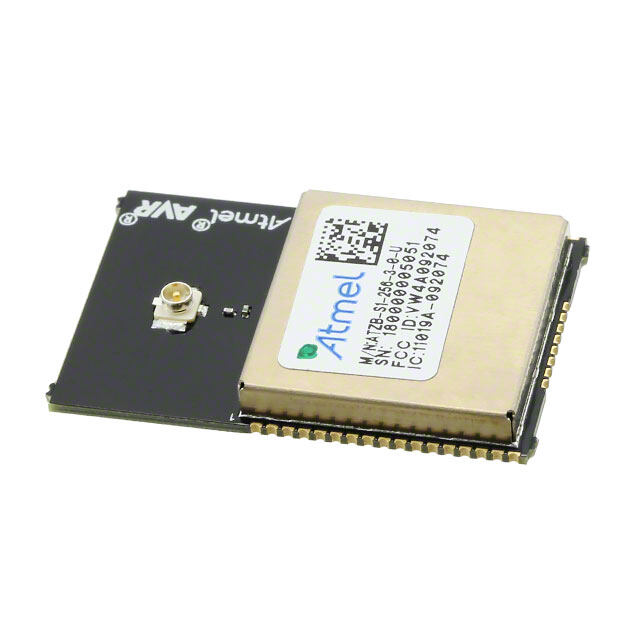
MRF24J40MA-I/RM 是由 Microchip Technology 生产的一款 RF 收发器模块,工作在 2.4 GHz 频段。它是一款基于 IEEE 802.15.4 标准的收发器模块,适用于多种无线通信应用场景,尤其是在低功耗、短距离无线网络中表现优异。以下是 MRF24J40MA-I/RM 的主要应用场景:

 1. 智能家居
   MRF24J40MA-I/RM 可用于智能家居设备中的无线通信,如智能灯泡、智能插座、温控器等。通过 Zigbee 或其他基于 IEEE 802.15.4 协议的网络协议,它可以实现设备之间的相互通信和远程控制。该模块的低功耗特性使其非常适合电池供电的设备,延长了设备的使用寿命。

 2. 工业自动化
   在工业环境中,MRF24J40MA-I/RM 可以用于传感器网络、数据采集系统和机器间通信。例如,在工厂中,它可以用于监控温度、湿度、压力等环境参数,并将数据传输到中央控制系统。其高可靠性和抗干扰能力确保了工业环境下稳定的数据传输。

 3. 医疗设备
   MRF24J40MA-I/RM 可应用于可穿戴医疗设备或远程健康监测系统。例如,心率监测器、血糖仪等设备可以通过该模块将数据传输到智能手机或其他终端设备,便于医生实时监控患者的健康状况。该模块的低功耗特性使得这些设备可以长时间运行而无需频繁充电。

 4. 农业物联网
   在农业领域,MRF24J40MA-I/RM 可用于智能灌溉系统、土壤湿度监测、气象站等应用。通过无线网络,农民可以实时获取农田的各种环境数据,从而优化种植和管理策略,提高农作物产量。

 5. 楼宇自动化
   该模块可用于楼宇自动化系统中的门禁控制、照明控制、安防监控等。通过无线网络,建筑物内的各种设备可以相互通信,实现智能化管理和节能控制。

 6. 消费电子
   在消费电子产品中,MRF24J40MA-I/RM 可用于遥控器、玩具、游戏控制器等设备。它的低延迟和可靠的通信性能为用户提供流畅的使用体验。

总之,MRF24J40MA-I/RM 凭借其低功耗、高可靠性和灵活的应用性,广泛适用于各类需要短距离无线通信的场景,尤其适合对功耗敏感的电池供电设备。
| 参数 | 数值 |
| 产品目录 | |
| 描述 | MODULE RF TXRX PICTAIL PLUSZigbee/802.15.4模块 2.4GHz IEEE 802.15.4 Transceiver Module |
| 产品分类 | RF 收发器射频/无线模块 |
| 品牌 | Microchip Technology |
| 产品手册 | |
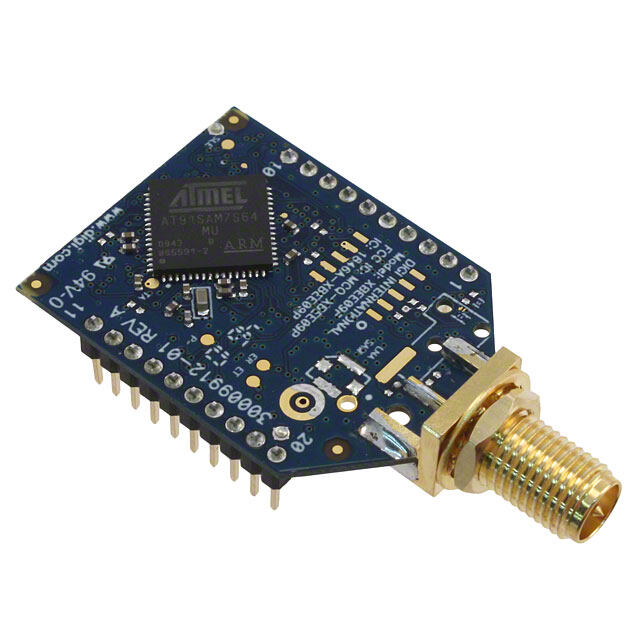
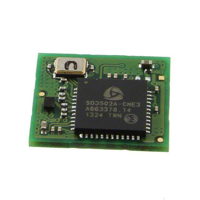
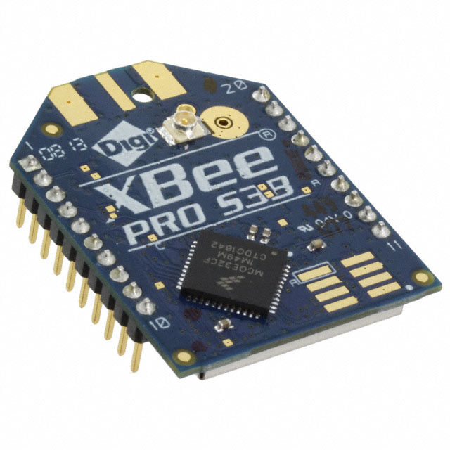
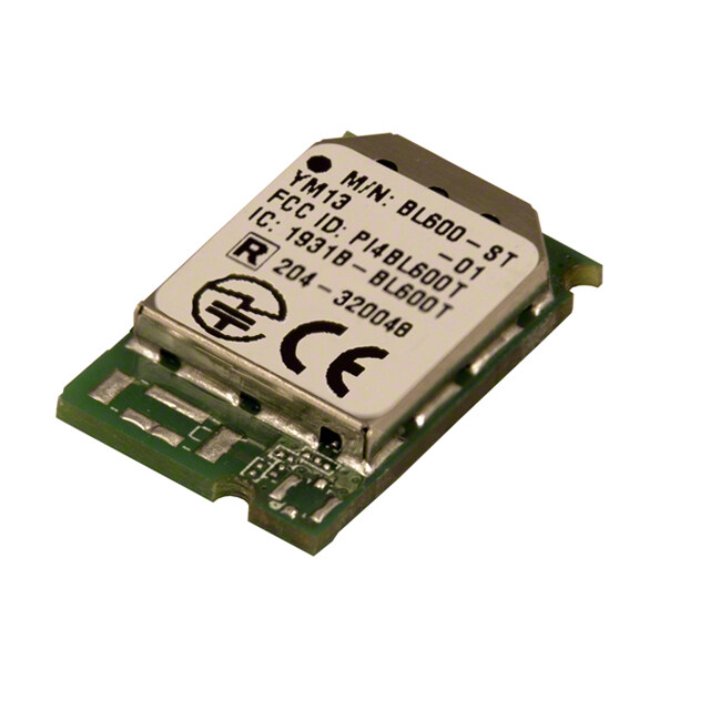
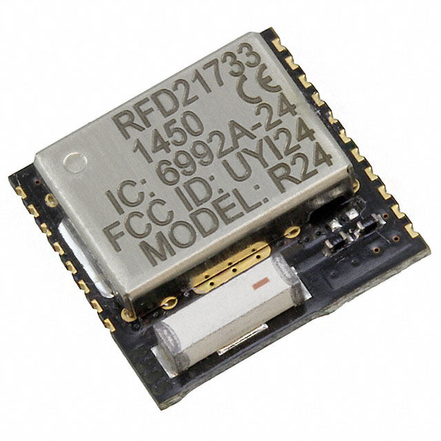
| 产品图片 |
|
| rohs | 符合RoHS无铅 / 符合限制有害物质指令(RoHS)规范要求 |
| 产品系列 | Zigbee/802.15.4模块,Microchip Technology MRF24J40MA-I/RM- |
| 数据手册 | http://www.microchip.com/mymicrochip/filehandler.aspx?ddocname=en536005 |
| 产品型号 | MRF24J40MA-I/RM |
| 产品种类 | Zigbee/802.15.4模块 |
| 传输供电电流 | 23 mA |
| 其它名称 | MRF24J40MA |
| 功率-输出 | 0dBm |
| 包装 | 托盘 |
| 参考设计库 | http://www.digikey.com/rdl/4294959884/4294959878/1109 |
| 商标 | Microchip Technology |
| 天线连接器 | 板载,跟踪 |
| 存储容量 | - |
| 封装 | Tray |
| 封装/外壳 | 模块 |
| 工作温度 | -40°C ~ 85°C |
| 工作电源电压 | 2.4 V to 3.6 V |
| 工厂包装数量 | 54 |
| 应用 | ISM,ZigBee™ |
| 接口类型 | 4-Wire SPI |
| 接收供电电流 | 19 mA |
| 数据接口 | PCB,表面贴装 |
| 数据速率 | 250 kbps |
| 数据速率(最大值) | 250kbps |
| 最大工作温度 | + 85 C |
| 最小工作温度 | - 40 C |
| 标准包装 | 54 |
| 灵敏度 | - 94 dBm |
| 电压-电源 | 2.4 V ~ 3.6 V |
| 电流-传输 | 23mA |
| 电流-接收 | 19mA |
| 调制或协议 | 802.15.4 |
| 输出功率 | 0 dBm |
| 频率 | 2.4GHz |


- 商务部:美国ITC正式对集成电路等产品启动337调查
- 曝三星4nm工艺存在良率问题 高通将骁龙8 Gen1或转产台积电
- 太阳诱电将投资9.5亿元在常州建新厂生产MLCC 预计2023年完工
- 英特尔发布欧洲新工厂建设计划 深化IDM 2.0 战略
- 台积电先进制程称霸业界 有大客户加持明年业绩稳了
- 达到5530亿美元!SIA预计今年全球半导体销售额将创下新高
- 英特尔拟将自动驾驶子公司Mobileye上市 估值或超500亿美元
- 三星加码芯片和SET,合并消费电子和移动部门,撤换高东真等 CEO
- 三星电子宣布重大人事变动 还合并消费电子和移动部门
- 海关总署:前11个月进口集成电路产品价值2.52万亿元 增长14.8%


PDF Datasheet 数据手册内容提取
MRF24J40MA Data Sheet 2.4 GHz IEEE Std. 802.15.4™ RF Transceiver Module © 2008 Microchip Technology Inc. DS70329B
Note the following details of the code protection feature on Microchip devices: • Microchip products meet the specification contained in their particular Microchip Data Sheet. • Microchip believes that its family of products is one of the most secure families of its kind on the market today, when used in the intended manner and under normal conditions. • There are dishonest and possibly illegal methods used to breach the code protection feature. All of these methods, to our knowledge, require using the Microchip products in a manner outside the operating specifications contained in Microchip’s Data Sheets. Most likely, the person doing so is engaged in theft of intellectual property. • Microchip is willing to work with the customer who is concerned about the integrity of their code. • Neither Microchip nor any other semiconductor manufacturer can guarantee the security of their code. Code protection does not mean that we are guaranteeing the product as “unbreakable.” Code protection is constantly evolving. We at Microchip are committed to continuously improving the code protection features of our products. Attempts to break Microchip’s code protection feature may be a violation of the Digital Millennium Copyright Act. If such acts allow unauthorized access to your software or other copyrighted work, you may have a right to sue for relief under that Act. Information contained in this publication regarding device Trademarks applications and the like is provided only for your convenience The Microchip name and logo, the Microchip logo, Accuron, and may be superseded by updates. It is your responsibility to dsPIC, KEELOQ, KEELOQ logo, MPLAB, PIC, PICmicro, ensure that your application meets with your specifications. PICSTART, rfPIC, SmartShunt and UNI/O are registered MICROCHIP MAKES NO REPRESENTATIONS OR trademarks of Microchip Technology Incorporated in the WARRANTIES OF ANY KIND WHETHER EXPRESS OR U.S.A. and other countries. IMPLIED, WRITTEN OR ORAL, STATUTORY OR OTHERWISE, RELATED TO THE INFORMATION, FilterLab, Linear Active Thermistor, MXDEV, MXLAB, INCLUDING BUT NOT LIMITED TO ITS CONDITION, SEEVAL, SmartSensor and The Embedded Control Solutions QUALITY, PERFORMANCE, MERCHANTABILITY OR Company are registered trademarks of Microchip Technology FITNESS FOR PURPOSE. Microchip disclaims all liability Incorporated in the U.S.A. arising from this information and its use. Use of Microchip Analog-for-the-Digital Age, Application Maestro, CodeGuard, devices in life support and/or safety applications is entirely at dsPICDEM, dsPICDEM.net, dsPICworks, dsSPEAK, ECAN, the buyer’s risk, and the buyer agrees to defend, indemnify and ECONOMONITOR, FanSense, In-Circuit Serial hold harmless Microchip from any and all damages, claims, Programming, ICSP, ICEPIC, Mindi, MiWi, MPASM, MPLAB suits, or expenses resulting from such use. No licenses are Certified logo, MPLIB, MPLINK, mTouch, PICkit, PICDEM, conveyed, implicitly or otherwise, under any Microchip PICDEM.net, PICtail, PIC32 logo, PowerCal, PowerInfo, intellectual property rights. PowerMate, PowerTool, REAL ICE, rfLAB, Select Mode, Total Endurance, WiperLock and ZENA are trademarks of Microchip Technology Incorporated in the U.S.A. and other countries. SQTP is a service mark of Microchip Technology Incorporated in the U.S.A. All other trademarks mentioned herein are property of their respective companies. © 2008, Microchip Technology Incorporated, Printed in the U.S.A., All Rights Reserved. Printed on recycled paper. Microchip received ISO/TS-16949:2002 certification for its worldwide headquarters, design and wafer fabrication facilities in Chandler and Tempe, Arizona; Gresham, Oregon and design centers in California and India. The Company’s quality system processes and procedures are for its PIC® MCUs and dsPIC® DSCs, KEELOQ® code hopping devices, Serial EEPROMs, microperipherals, nonvolatile memory and analog products. In addition, Microchip’s quality system for the design and manufacture of development systems is ISO 9001:2000 certified. DS70329B-page ii © 2008 Microchip Technology Inc.
MRF24J40MA 2.4 GHz IEEE Std. 802.15.4™ RF Transceiver Module Features: RF/Analog Features: • IEEE Std. 802.15.4™ Compliant RF Transceiver • ISM Band 2.405-2.48 GHz Operation • Supports ZigBee®, MiWi™, MiWi™ P2P and • Data Rate: 250kbps Proprietary Wireless Networking Protocols • -94 dBm Typical Sensitivity with +5 dBm • Small Size: 0.7” x 1.1” (17.8mm x 27.9mm), Maximum Input Level Surface Mountable • +0 dBm Typical Output Power with • Integrated Crystal, Internal Voltage Regulator, 36 dB TX Power Control Range Matching Circuitry and PCB Antenna • Integrated Low Phase Noise VCO, Frequency • Easy Integration into Final Product – Minimize Synthesizer and PLL Loop Filter Product Development, Quicker Time to Market • Digital VCO and Filter Calibration • Radio Regulation Certification for United States • Integrated RSSI ADC and I/Q DACs (FCC), Canada (IC) and Europe (ETSI) • Integrated LDO • Compatible with Microchip Microcontroller • High Receiver and RSSI Dynamic Range Families (PIC16F, PIC18F, PIC24F/H, dsPIC33 and PIC32) MAC/Baseband Features: • Up to 400 ft. Range • Hardware CSMA-CA Mechanism, Automatic ACK Operational: Response and FCS Check • Independent Beacon, Transmit and GTS FIFO • Operating Voltage: 2.4-3.6V (3.3V typical) • Supports all CCA modes and RSS/LQI • Temperature Range: -40°C to +85°C Industrial • Automatic Packet Retransmit Capable • Simple, Four-Wire SPI Interface • Hardware Security Engine (AES-128) with CTR, • Low-Current Consumption: CCM and CBC-MAC modes - RX mode: 19mA (typical) • Supports Encryption and Decryption for MAC - TX mode: 23mA (typical) Sublayer and Upper Layer - Sleep: 2 μA (typical) FIGURE 1: PIN DIAGRAM GND 1 12 GND RESET 2 11 GND WAKE 3 10 VIN INT 4 9 NC SDI 5 8 CS SCK 6 7 SDO © 2008 Microchip Technology Inc. DS70329B-page 1
MRF24J40MA Table of Contents 1.0 Device Overview..........................................................................................................................................................................3 2.0 Circuit Description........................................................................................................................................................................7 3.0 Regulatory Approval...................................................................................................................................................................15 4.0 Electrical Characteristics............................................................................................................................................................19 Appendix A: Revision History...............................................................................................................................................................21 Index....................................................................................................................................................................................................23 The Microchip Web Site.......................................................................................................................................................................25 Customer Change Notification Service................................................................................................................................................25 Customer Support................................................................................................................................................................................25 Reader Response................................................................................................................................................................................26 Product Identification System...............................................................................................................................................................27 TO OUR VALUED CUSTOMERS It is our intention to provide our valued customers with the best documentation possible to ensure successful use of your Microchip products. To this end, we will continue to improve our publications to better suit your needs. Our publications will be refined and enhanced as new volumes and updates are introduced. If you have any questions or comments regarding this publication, please contact the Marketing Communications Department via E-mail at docerrors@microchip.com or fax the Reader Response Form in the back of this data sheet to (480) 792-4150. We welcome your feedback. Most Current Data Sheet To obtain the most up-to-date version of this data sheet, please register at our Worldwide Web site at: http://www.microchip.com You can determine the version of a data sheet by examining its literature number found on the bottom outside corner of any page. The last character of the literature number is the version number, (e.g., DS30000A is version A of document DS30000). Errata An errata sheet, describing minor operational differences from the data sheet and recommended workarounds, may exist for current devices. As device/documentation issues become known to us, we will publish an errata sheet. The errata will specify the revision of silicon and revision of document to which it applies. To determine if an errata sheet exists for a particular device, please check with one of the following: • Microchip’s Worldwide Web site; http://www.microchip.com • Your local Microchip sales office (see last page) When contacting a sales office, please specify which device, revision of silicon and data sheet (include literature number) you are using. Customer Notification System Register on our web site at www.microchip.com to receive the most current information on all of our products. DS70329B-page 2 © 2008 Microchip Technology Inc.
MRF24J40MA 1.0 DEVICE OVERVIEW MRF24J40MA module inside a finished product and not require regulatory testing for an intentional radiator The MRF24J40MA is a 2.4 GHz IEEE Std. 802.15.4™ (RF transmitter). See Section3.0 “Regulatory compliant, surface mount module with integrated Approval” for specific requirements to be followed by crystal, internal voltage regulator, matching circuitry the integrator. and PCB antenna. The MRF24J40MA module oper- ates in the non-licensed 2.4 GHz frequency band and 1.1 Interface Description is FCC, IC and ETSI compliant. The integrated module design frees the integrator from extensive RF and Figure1-1 shows a simplified block diagram of the antenna design, and regulatory compliance testing, MRF24J40MA module. The module is based on the allowing quicker time to market. Microchip Technology MRF24J40 IEEE 802.15.4™ 2.4GHz RF Transceiver IC. The module interfaces to The MRF24J40MA module is compatible with Microchip’s ZigBee®, MiWi™ and MiWi P2P software many popular Microchip PIC® microcontrollers via a 4-wire serial SPI interface, interrupt, wake, Reset, stacks. Each software stack is available as a free power and ground, as shown in Figure1-2. Table1-1 download, including source code, from the Microchip provides the pin descriptions. web site http://www.microchip.com/wireless. Data communications with the MRF24J40MA module The MRF24J40MA module has received regulatory are documented in the “MRF24J40 IEEE 802.15.4™ approvals for modular devices in the United States 2.4GHz RF Transceiver Data Sheet” (DS39776). Refer (FCC), Canada (IC) and Europe (ETSI). Modular to the MRF24J40 Data Sheet for specific serial approval removes the need for expensive RF and interface protocol and register definitions. antenna design and allows the end user to place the FIGURE 1-1: MRF24J40MA BLOCK DIAGRAM MRF24J40MA IEEE Std. 802.15.4™ Module MRF24J40 Digital Interface SPI I/O PCB Matching Physical MAC Antenna Circuitry Power Power Management 20 MHz Crystal © 2008 Microchip Technology Inc. DS70329B-page 3
MRF24J40MA TABLE 1-1: PIN DESCRIPTION Pin Symbol Type Description 1 GND Power Ground 2 RESET DI Global hardware Reset pin 3 WAKE DI External wake-up trigger 4 INT DO Interrupt pin to microcontroller 5 SDI DI Serial interface data input 6 SCK DI Serial interface clock 7 SDO DO Serial interface data output from MRF24J40 8 CS DI Serial interface enable 9 NC — No connection (allow pin to float; do not connect signal) 10 VIN Power Power supply 11 GND Ground Ground 12 GND Ground Ground Legend: Pin type abbreviation: D = Digital, I = Input, O = Output FIGURE 1-2: MICROCONTROLLER TO MRF24J40MA INTERFACE PIC® MCU MRF24J40MA I/O CS SDO SDI SDI SDO SCK SCK VIN GND INTx INT I/O WAKE I/O RESET DS70329B-page 4 © 2008 Microchip Technology Inc.
MRF24J40MA 1.2 Mounting Details FIGURE 1-4: RECOMMENDED PCB FOOTPRINT The MRF24J40MA is a surface mountable module. Module dimensions are shown in Figure1-3. The module Printed Circuit Board (PCB) is 0.032" thick with castellated mounting points on the edge. Figure1-4 is a recommended host PCB footprint for the MRF24J40MA. The MRF24J40MA has an integrated PCB antenna. For the best performance, follow the mounting details shown in Figure1-5. It is recommended that the module be mounted on the edge of the host PCB, and an area around the antenna, approximately 1.2", be kept clear of metal objects. A host PCB ground plane around the MRF24J40MA acts as a counterpoise to the PCB antenna. It is recommended to extend the ground plane at least 0.4" around the module. FIGURE 1-3: MODULE DETAILS © 2008 Microchip Technology Inc. DS70329B-page 5
MRF24J40MA FIGURE 1-5: MOUNTING DETAILS Keep area around antenna (approximately 1.2 inches) 1.2” clear of metallic structures for best performance Edge of PCB 1.2” 0.470” 0.4” 0.4” 0.4” PCB Ground Plane (Counterpoise) Extend as far as possible to the sides and below the module (at least 0.4 inches on each side) for best performance DS70329B-page 6 © 2008 Microchip Technology Inc.
MRF24J40MA 2.0 CIRCUIT DESCRIPTION 2.1 Schematic The MRF24J40MA is a complete 2.4 GHz IEEE A schematic diagram of the module is shown in Std.802.15.4™ compliant surface mount module with Figure2-1 and the Bill of Materials (BOM) is shown in integrated crystal, internal voltage regulator, matching Table2-1. circuitry and PCB antenna. The MRF24J40MA module The MRF24J40MA module is based on the Microchip interfaces to many popular Microchip PIC micro- Technology MRF24J40 IEEE 802.15.4™ 2.4 GHz RF controllers via a 4-wire serial SPI interface, interrupt, Transceiver IC. The serial I/O (SCK, SDI, SDO and wake, Reset, power and ground. Data communications CS), RESET, WAKE and INT pins are brought out to with the MRF24J40MA module are documented in the the module pins. The SDO signal is tri-state buffered by “MRF24J40 IEEE 802.15.4™ 2.4 GHz RF Transceiver IC2 to solve a silicon errata, where the SDO signal Data Sheet” (DS39776). Refer to the MRF24J40 Data does not release to a high-impedance state, after the Sheet for specific serial interface protocol and register CS pin returns to its inactive state. Crystal, X1, is a definitions. 20MHz crystal with a frequency tolerance of ±10ppm@25°C to meet the IEEE Std. 802.15.4 symbol rate tolerance of ±40 ppm. A balun is formed by components: L1, L3, C2 and C14. L2 is an RF choke and pull-up for the RFP and RFN pins on the MRF24J40. C15 is a DC block capacitor. A low-pass filter is formed by components: L4, C16 and C17. The remaining capacitors provide RF and digital bypass. Advance Information © 2008 Microchip Technology Inc. DS70329B-page 7
MRF24J40MA FIGURE 2-1: MRF24J40MA SCHEMATIC D D N D N N VI N G G O 10 1 G 11 12 NC 8 CS P5X 7 SD 5 2 1 VIN 7SZ C11 Fμ VIN C547 pF VIN C30.01 Fμ VIN 5VIC2CCNCOE4YA GND3 F 12 p C447 N VI E ET C1918 pF 20.00 MHz C1818 pF 30NCNC29NCNC28SC1NC27SC2NC26NC25GND24GND23NCNC22GND21VDD 6 SCK 5 SDI 4 INT 3 WAK 2 RES X1 CN 09876543214333333333 12DCPDDDDDCSDDDDDANNVVVVVCSCGOOL LPOLPOIC1MRF24J40/ML T23EEOOKDOSKIIIATNPPESDDCNWGGGRCSSSI 12345678901111111112 1P 0154 RN DDFPFNDDDDNDPIOPIOPIOPIO VRRVVGGGGG 9F C00 p 12345678910 VIN 1 N VI 8F Cμ 1 N VI H H 1F VIN VIN C70.01 Fμ VIN L2C143.3 n0.5 pF L18.2 nL35.6 nH C21.0 pF VIN C1047 pF C10.1 μ 6F Cp 7 3F 4 C147 p C150.5 pF d. C120.1 Fμ L48 nH C16NP Not Place 6. = P N 7F 1p C0 e: 1. ot N a CBenn Pnt A Advance Information DS70329B-page 8 © 2008 Microchip Technology Inc.
MRF24J40MA TABLE 2-1: MRJ24J40MA BILL OF MATERIALS Designator Description Manufacturer Part Number C1 Chip Capacitor 0402 X5R 1U Murata GRM155R60J105ME19D C2 Chip Capacitor 0402 COG 1.0P Murata GRM1555C1H1R0CZ01D C3 Chip Capacitor 0402 X7R 10N Murata GRM155R71E103KA01D C4 Chip Capacitor 0402 COG 47P Murata GRM1555C1H470JZ01D C5 Chip Capacitor 0402 COG 47P Murata GRM1555C1H470JZ01D C6 Chip Capacitor 0402 COG 47P Murata GRM1555C1H470JZ01D C7 Chip Capacitor 0402 X7R 10N Murata GRM155R71E103KA01D C8 Chip Capacitor 0402 X5R 1U Murata GRM155R60J105ME19D C9 Chip Capacitor 0402 COG 100P Murata GRM1555C1H101JZ01D C10 Chip Capacitor 0402 COG 47P Murata GRM1555C1H470JZ01D C11 Chip Capacitor 0402 X5R 100N Murata GRM155R61A104KA01D C12 Chip Capacitor 0402 X5R 100N Murata GRM155R61A104KA01D C13 Chip Capacitor 0402 COG 47P Murata GRM1555C1H470JZ01D C14 Chip Capacitor 0402 COG 0.5P Murata GRM1555C1HR50CZ01D C15 Chip Capacitor 0402 COG 0.5P Murata GRM1555C1HR50CZ01D C16 Not Placed C17 Chip Capacitor 0402 COG 1.0P Murata GRM1555C1H1R0CZ01D C18 Chip Capacitor 0402 COG 18P Murata GRM1555C1H180JZ01D C19 Chip Capacitor 0402 COG 18P Murata GRM1555C1H180JZ01D IC1 IEEE 802.15.4™ RF Transceiver Microchip MRF24J40-I/ML IC2 Buffer, SC70 Package Fairchild NC7SZ125P5X L1 Chip Inductor 0402 8.2N Panasonic ELJ-RF8N2JFB L2 Chip Inductor 0402 3.3N Panasonic ELJ-RF3N3DFB L3 Chip Inductor 0402 5.6N Panasonic ELJ-RF5N6DFB L4 Chip Inductor 0402 6.8N Panasonic ELJ-RF6N8JFB R1 Not Placed X1 20 MHz Crystal Abracon ABM8-156-20.0000MHZ-T Advance Information © 2008 Microchip Technology Inc. DS70329B-page 9
MRF24J40MA 2.2 Printed Circuit Board FIGURE 2-5: LAYER 3 – POWER PLANE The MRF24J40MA module printed circuit board is con- structed with FR4 material, four layers and 0.032inches thick. The layers are shown in Figure2-2 through Figure2-6. The stack up of the PCB is shown in Figure2-7. FIGURE 2-2: TOP SILK SCREEN Note: Top view negative Gerber. FIGURE 2-6: BOTTOM COPPER FIGURE 2-3: TOP COPPER Note: Top view. FIGURE 2-4: LAYER 2 – GROUND PLANE Note: Top view negative Gerber. Advance Information DS70329B-page 10 © 2008 Microchip Technology Inc.
MRF24J40MA FIGURE 2-7: PCB LAYER STACK UP 1/2 oz. Copper Top Copper 8 mil FR4 1/2 oz. Copper Ground Plane 0.032” 12 mil FR4 +/- 0.005” 1/2 oz. Copper Power Plane 8 mil FR4 1/2 oz. Copper Bottom Copper Advance Information © 2008 Microchip Technology Inc. DS70329B-page 11
MRF24J40MA 2.3 PCB Antenna FIGURE 2-8: PCB ANTENNA DIMENSIONS The PCB antenna is fabricated on the top copper trace. Figure2-8 shows the trace dimensions. The layers 16.5 mm below the antenna have no copper traces. The ground and power planes under the components serve as a counterpoise to the PCB antenna. Additional ground 4.0 mm plane on the host PCB will substantially enhance the performance of the module. For best performance, 11.0 mm place the module on the host PCB following the recommendations in Section1.2 “Mounting Details”. The Printed Circuit Board (PCB) antenna was designed and simulated using Ansoft Designer® and HFSS™ 3D full-wave solver software by Ansoft Corporation (www.ansoft.com). The design goal was to create a 2.0 mm 2.5 mm compact, low-cost antenna with the best radiation 5.0 mm pattern. Figure2-9 shows the simulation drawing and Figure2-10 and Figure2-11 show the 2D and 3D radiation patterns, respectively. As shown by the radiation patterns, the performance of the antenna is dependant upon the orientation of the module. Figure2-12 shows the impedance simulation and Figure2-13 shows the actual impedance measurement. The discrete matching circuitry matches the impedance of the antenna with the MRF24J40 transceiver IC. FIGURE 2-9: PCB ANTENNA SIMULATION DRAWING Z Y X Advance Information DS70329B-page 12 © 2008 Microchip Technology Inc.
MRF24J40MA FIGURE 2-10: SIMULATED 2D RADIATION PATTERN FIGURE 2-11: SIMULATED 3D RADIATION PATTERN dB (Gain Total) Z 2.0921e+000 1.1359e-001 -1.8649e+000 Theta -3.8435e+000 -5.8220e+000 -7.8005e+000 -9.7791e+000 -1.1758e-001 -1.3736e+001 -1.5715e+001 -1.7693e+001 Y -1.9672e+001 -2.1650e+001 Phi -2.3629e-001 -2.5607e+001 X -2.7586e+001 -2.9564e+001 Advance Information © 2008 Microchip Technology Inc. DS70329B-page 13
MRF24J40MA FIGURE 2-12: SIMULATED PCB ANTENNA IMPEDANCE FIGURE 2-13: MEASURED PCB ANTENNA IMPEDANCE Advance Information DS70329B-page 14 © 2008 Microchip Technology Inc.
MRF24J40MA 3.0 REGULATORY APPROVAL The user’s manual should include the following statement: The MRF24J40MA module has received regulatory approvals for modular devices in the United States, This equipment has been tested and found to comply Canada and European countries. Modular approval with the limits for a Class B digital device, pursuant to allows the end user to place the MRF24J40MA module part 15 of the FCC Rules. These limits are designed to inside a finished product and not require regulatory provide reasonable protection against harmful testing for an intentional radiator (RF transmitter), pro- interference in a residential installation. This vided no changes or modifications are made to the equipment generates, uses and can radiate radio module circuitry. Changes or modifications could void frequency energy, and if not installed and used in the user’s authority to operate the equipment. The end accordance with the instructions, may cause harmful user must comply with all of the instructions provided interference to radio communications. However, there by the Grantee, which indicate installation and/or is no guarantee that interference will not occur in a operating conditions necessary for compliance. particular installation. If this equipment does cause The integrator may still be responsible for testing the end harmful interference to radio or television reception, product for any additional compliance requirements which can be determined by turning the equipment off required with this module installed (for example: digital and on, the user is encouraged to try to correct the device emission, PC peripheral requirements, etc.) in interference by one or more of the following measures: the specific country that the end device will be marketed. • Reorient or relocate the receiving antenna. Annex F of the IEEE Std. 802.15.4 document has a good • Increase the separation between the equipment summary of regulatory requirements in various countries and receiver. concerning IEEE Std. 802.15.4 devices. The standard • Connect the equipment into an outlet on a can be downloaded from the IEEE Standards web page: circuit different from that to which the receiver is http://standards.ieee.org/getieee802/802.15.html. connected. Refer to the specific country radio regulations for • Consult the dealer or an experienced radio/TV details on regulatory compliance. technician for help. 3.1 United States 3.1.1 RF EXPOSURE The MRF24J40MA has received Federal Communica- All transmitters regulated by FCC must comply with RF tions Commission (FCC) CFR47 Telecommunications, exposure requirements. OET Bulletin 65 “Evaluating Part 15 Subpart C “Intentional Radiators” 15.247 and Compliance with FCC Guidelines for Human Exposure modular approval in accordance with FCC Public to Radio Frequency Electromagnetic Fields” provides Notice DA 00-1407 Released: June 26, 2000, Part 15 assistance in determining whether proposed or existing Unlicensed Modular Transmitter Approval. The transmitting facilities, operations or devices comply MRF24J40MA module can be integrated into a finished with limits for human exposure to Radio Frequency product without obtaining subsequent and separate (RF) fields adopted by the Federal Communications FCC approvals. Commission (FCC). The bulletin offers guidelines and suggestions for evaluating compliance. The MRF24J40MA module has been labeled with its own FCC ID number, and if the FCC ID is not visible If appropriate, compliance with exposure guidelines for when the module is installed inside another device, mobile and unlicensed devices can be accomplished then the outside of the finished product into which the by the use of warning labels and by providing users module is installed must also display a label referring to with information concerning minimum separation the enclosed module. This exterior label can use distances from transmitting structures and proper wording such as the following: installation of antennas. Contains Transmitter Module FCC ID: OA3MRF24J40MA -or- Contains FCC ID: OA3MRF24J40MA This device complies with Part 15 of the FCC Rules. Operation is subject to the following two conditions: (1) this device may not cause harmful interference, and (2) this device must accept any interference received, including interference that may cause undesired operation. © 2008 Microchip Technology Inc. DS70329B-page 15
MRF24J40MA The following statement must be included as a From Section 5.2, RSS-Gen, Issue 2, June 2007, CAUTION statement in manuals and OEM products to Equipment Labels: alert users of FCC RF Exposure compliance: All Category I radio equipment intended for use in Canada shall permanently display on each transmitter, To satisfy FCC RF Exposure requirements for mobile receiver or inseparable combination thereof, the and base station transmission devices, a separation applicant’s name (i.e., manufacturer’s name, trade distance of 20 cm or more should be maintained name or brand name), model number and certification between the antenna of this device and persons number. This information shall be affixed in such a during operation. To ensure compliance, operation at manner as to not be removable except by destruction or closer than this distance is not recommended. defacement. The size of the lettering shall be legible The antenna(s) used for this transmitter must not be without the aid of magnification, but is not required to be co-located or operating in conjunction with any other larger than 8-point font size. If the device is too small to antenna or transmitter. meet this condition, the information can be included in the user manual upon agreement with Industry Canada. Label: If the MRF24J40MA module is used in a portable application (antenna is less than 20 cm from persons Contains IC: 7693A-24J40MA during operation), the integrator is responsible for performing Specific Absorption Rate (SAR) testing in From Section 7.1.6, RSS-Gen, Issue 2, June 2007, accordance with FCC rules 2.1091. Digital Circuits: If the device contains digital circuitry that is not directly 3.1.2 HELPFUL WEB SITES associated with the radio transmitter, the device shall Federal Communications Commission (FCC): also have to comply with ICES-003, Class A or B as http://www.fcc.gov appropriate, except for ICES-003 labeling requirements. The test data obtained (for the ICES-003 3.2 Canada tests) shall be kept by the manufacturer or importer whose name appears on the equipment label, and The MRF24J40MA module has been certified for use in made available to Industry Canada on request, for as Canada under Industry Canada (IC) Radio Standards long as the model is being marketed in Canada. Specification (RSS) RSS-210 and RSS-Gen. 3.2.1 HELPFUL WEB SITES From Section 7.1.1, RSS-Gen, Issue 2, June 2007, Modular Transmitter Approval: Industry Canada: http://www.ic.gc.ca/ Host devices which contain separately certified modules do not need to be recertified, provided that they meet the following conditions: a) The host device, as a stand-alone unit without any separately certified modules, complies with all applicable Radio Standards Specifications. b) The host device and all the separately certified modules it contains jointly meet the RF exposure compliance requirements of RSS-102, if applicable. c) The host device complies with the certification labeling requirements of each of the modules it contains. Note: Compliance of a module in its final configuration is the responsibility of the applicant. A host device will not be considered certified if the instructions regarding antenna configuration provided in the original description, of one or more separately certified modules it contains, were not followed DS70329B-page 16 © 2008 Microchip Technology Inc.
MRF24J40MA 3.3 Europe The end user is responsible for ensuring compliance with harmonized frequencies and labeling The MRF24J40MA module has been certified for use in requirements for each country the end device is European countries. The following testing has been marketed and sold. completed: 3.3.1 HELPFUL WEB SITES: Test standard ETSI EN 300 328 V1.7.1 (2006-10): • Maximum Transmit Power Radio and Telecommunications Terminal Equipment (R&TTE): • Maximum EIRP Spectral Density http://ec.europa.eu/enterprise/rtte/index_en.htm • Frequency Range European Conference of Postal and Telecommunications • Radiated Emissions Administrations (CEPT): http://www.cept.org/ Test standards ETSI EN 301 489-1:2008 and ETSI European Telecommunications Standards Institute EN301 489-17:2008: (ETSI): http://www.etsi.org/ • Radiated Emissions European Radio Communications Office (ERO): • Electro-Static Discharge http://www.ero.dk/ • Radiated RF Susceptibility A helpful document that can be used as a starting point in understanding the use of Short Range Devices (SRD) in Europe is the European Radio Communications Com- mittee (ERC) Recommendation 70-03 E, downloadable from the European Radio Communications Office (ERO): http://www.ero.dk. © 2008 Microchip Technology Inc. DS70329B-page 17
MRF24J40MA NOTES: DS70329B-page 18 © 2008 Microchip Technology Inc.
MRF24J40MA 4.0 ELECTRICAL CHARACTERISTICS TABLE 4-1: RECOMMENDED OPERATING CONDITIONS Parameters Min Typ Max Units Ambient Operating Temperature -40 — +85 °C Supply Voltage for RF, Analog and 2.4 — 3.6 V Digital Circuits Supply Voltage for Digital I/O 2.4 3.3 3.6 V Input High Voltage (VIH) 0.5 x VDD — VDD + 0.3 V Input Low Voltage (VIL) -0.3 — 0.2 x VDD V TABLE 4-2: CURRENT CONSUMPTION (TA = 25°C, VDD = 3.3V) Chip Mode Condition Min Typ Max Units Sleep Sleep Clock Disabled — 2 — μA TX At Maximum Output Power — 23 — mA RX — 19 — mA TABLE 4-3: RECEIVER AC CHARACTERISTICS Typical values are at TA = 25°C, VDD = 3.3V, LO Frequency = 2.445 GHz Parameters Condition Min Typ Max Units RF Input Frequency Compatible to 2.405 — 2.480 GHz IEEE Std. 802.15.4™, 2003 RF Sensitivity — -94 — dBm Maximum RF Input +5 — — dBm LO Leakage Measured at Balun Matching — -60 — dBm Network Input at Frequency, 2.405-2.48 GHz Input Return Loss Externally Matched to 50 ohm Source -8 -12 — dB by a Balun Matching Network Noise Figure — 8 — dB (including matching) Adjacent Channel @ +/-5 MHz 30 — — dB Rejection Alternate Channel @ +/-10 MHz 40 — — dB Rejection RSSI Range — 50 — dB RSSI Error -5 — 5 dB © 2008 Microchip Technology Inc. DS70329B-page 19
MRF24J40MA TABLE 4-4: TRANSMITTER AC CHARACTERISTICS Typical values are at TA = 25°C, VDD = 3.3V, LO Frequency = 2.445 GHz Parameters Condition Min Typ Max Units RF Carrier Frequency 2.405 — 2.480 GHz Maximum RF Output — 0 — dBm Power RF Output Power — 36 — dB Control Range TX Gain Control Programmed by Register — 1.25 — dB Resolution Carrier Suppression — -30 — dBc TX Spectrum Mask for Offset Frequency > 3.5 MHz, -33 — — dBm O-QPSK Signal at 0dBm Output Power TX EVM — 15 — % DS70329B-page 20 © 2008 Microchip Technology Inc.
MRF24J40MA APPENDIX A: REVISION HISTORY Revision A (June 2008) Original data sheet for the MRF24J40MA device. Revision B (November 2008) Changed C17 to 1.0 pF and removed CLKOUT signal. © 2008 Microchip Technology Inc. DS70329B-page 21
MRF24J40MA NOTES: DS70329B-page 22 © 2008 Microchip Technology Inc.
MRF24J40MA INDEX A O AC Characteristics Overview...............................................................................3 Receiver......................................................................19 P Transmitter..................................................................20 Antenna Impedance PCB Antenna......................................................................12 Measured PCB............................................................14 Dimensions.................................................................12 Simulated PCB............................................................14 Simulation Drawing.....................................................12 PCB Layers B Bottom Copper............................................................10 Block Diagrams Layer 2 – Ground Plane..............................................10 Microcontroller to MRF24J40MA Interface....................4 Layer 3 – Power Plane...............................................10 MRF24J40MA...............................................................3 Stack Up.....................................................................11 Top Copper.................................................................10 C Top Silk Screen..........................................................10 Circuit Description.................................................................7 Pin Description......................................................................4 Customer Change Notification Service...............................24 Pin Diagram..........................................................................1 Customer Notification Service.............................................24 Printed Circuit Board (PCB)................................................10 Customer Notification System...............................................2 R Customer Support...............................................................24 Radiation Pattern E 2D...............................................................................13 Electrical Characteristics.....................................................19 3D...............................................................................13 Current Consumption..................................................19 Reader Response...............................................................25 Recommended Operating Conditions.........................19 Regulatory Approval...........................................................15 Errata.....................................................................................2 Canada.......................................................................16 European Radio Communications (ERC)............................17 Europe........................................................................17 United States..............................................................15 F Revision History..................................................................21 FCC ID Number...................................................................15 RF Exposure.......................................................................15 FCC RF Exposure Compliance...........................................16 RF/Analog Features..............................................................1 H S Helpful Web Sites..........................................................16, 17 Serial I/O I SCK, SDI, SDO, CS......................................................7 Short Range Devices (SRD)...............................................17 Interface Description.............................................................3 Specific Absorption Rate (SAR)..........................................16 Internet Address..................................................................24 SPI........................................................................................7 M W MAC/Baseband Features......................................................1 WWW Address....................................................................24 Microchip Internet Web Site................................................24 WWW, On-Line Support.......................................................2 MiWi P2P...............................................................................3 MiWi Protocol........................................................................3 Z More Information...................................................................2 ZigBee Protocol....................................................................3 Customer Notification System.......................................2 Errata............................................................................2 Mounting Details....................................................................5 MRF24J40 Data Sheet......................................................3, 7 MRF24J40MA Bill of Materials (BOM)..................................9 MRF24J40MA Schematic......................................................8 DS70329B-page 23 © 2008 Microchip Technology Inc.
MRF24J40MA NOTES: DS70329B-page 24 © 2008 Microchip Technology Inc.
MRF24J40MA THE MICROCHIP WEB SITE CUSTOMER SUPPORT Microchip provides online support via our WWW site at Users of Microchip products can receive assistance www.microchip.com. This web site is used as a means through several channels: to make files and information easily available to • Distributor or Representative customers. Accessible by using your favorite Internet • Local Sales Office browser, the web site contains the following • Field Application Engineer (FAE) information: • Technical Support • Product Support – Data sheets and errata, • Development Systems Information Line application notes and sample programs, design resources, user’s guides and hardware support Customers should contact their distributor, documents, latest software releases and archived representative or field application engineer (FAE) for software support. Local sales offices are also available to help • General Technical Support – Frequently Asked customers. A listing of sales offices and locations is Questions (FAQ), technical support requests, included in the back of this document. online discussion groups, Microchip consultant Technical support is available through the web site program member listing at: http://support.microchip.com • Business of Microchip – Product selector and ordering guides, latest Microchip press releases, listing of seminars and events, listings of Microchip sales offices, distributors and factory representatives CUSTOMER CHANGE NOTIFICATION SERVICE Microchip’s customer notification service helps keep customers current on Microchip products. Subscribers will receive e-mail notification whenever there are changes, updates, revisions or errata related to a specified product family or development tool of interest. To register, access the Microchip web site at www.microchip.com, click on Customer Change Notification and follow the registration instructions. © 2008 Microchip Technology Inc. DS70329B-page 25
MRF24J40MA READER RESPONSE It is our intention to provide you with the best documentation possible to ensure successful use of your Microchip prod- uct. If you wish to provide your comments on organization, clarity, subject matter, and ways in which our documentation can better serve you, please FAX your comments to the Technical Publications Manager at (480) 792-4150. Please list the following information, and use this outline to provide us with your comments about this document. To: Technical Publications Manager Total Pages Sent ________ RE: Reader Response From: Name Company Address City / State / ZIP / Country Telephone: (_______) _________ - _________ FAX: (______) _________ - _________ Application (optional): Would you like a reply? Y N Device: MRF24J40MA Literature Number: DS70329B Questions: 1. What are the best features of this document? 2. How does this document meet your hardware and software development needs? 3. Do you find the organization of this document easy to follow? If not, why? 4. What additions to the document do you think would enhance the structure and subject? 5. What deletions from the document could be made without affecting the overall usefulness? 6. Is there any incorrect or misleading information (what and where)? 7. How would you improve this document? DS70329B-page 26 © 2008 Microchip Technology Inc.
MRF24J40MA PRODUCT IDENTIFICATION SYSTEM To order or obtain information, e.g., on pricing or delivery, refer to the factory or the listed sales office. PART NO. M X T -X Examples: Device Module Module Tape and Temperature a) MRF24J40MA-I = Industrial temp. tray Type Reel Range b) MRF24J40MAT-I = Industrial temp., tape and reel. Device MRF24J40MA; VDD range 2.4V to 3.6V Temperature Range I = -40°C to +85°C (Industrial) © 2008 Microchip Technology Inc. DS70329B-page 27
WORLDWIDE SALES AND SERVICE AMERICAS ASIA/PACIFIC ASIA/PACIFIC EUROPE Corporate Office Asia Pacific Office India - Bangalore Austria - Wels 2355 West Chandler Blvd. Suites 3707-14, 37th Floor Tel: 91-80-4182-8400 Tel: 43-7242-2244-39 Chandler, AZ 85224-6199 Tower 6, The Gateway Fax: 91-80-4182-8422 Fax: 43-7242-2244-393 Tel: 480-792-7200 Harbour City, Kowloon India - New Delhi Denmark - Copenhagen Fax: 480-792-7277 Hong Kong Tel: 91-11-4160-8631 Tel: 45-4450-2828 Technical Support: Tel: 852-2401-1200 Fax: 91-11-4160-8632 Fax: 45-4485-2829 http://support.microchip.com Web Address: Fax: 852-2401-3431 India - Pune France - Paris www.microchip.com Australia - Sydney Tel: 91-20-2566-1512 Tel: 33-1-69-53-63-20 Tel: 61-2-9868-6733 Fax: 91-20-2566-1513 Fax: 33-1-69-30-90-79 ADtullaunthta, GA Fax: 61-2-9868-6755 Japan - Yokohama Germany - Munich Tel: 678-957-9614 China - Beijing Tel: 81-45-471- 6166 Tel: 49-89-627-144-0 Tel: 86-10-8528-2100 Fax: 49-89-627-144-44 Fax: 678-957-1455 Fax: 81-45-471-6122 Fax: 86-10-8528-2104 Italy - Milan Boston Korea - Daegu Westborough, MA China - Chengdu Tel: 82-53-744-4301 Tel: 39-0331-742611 Tel: 774-760-0087 Tel: 86-28-8665-5511 Fax: 82-53-744-4302 Fax: 39-0331-466781 Fax: 774-760-0088 Fax: 86-28-8665-7889 Korea - Seoul Netherlands - Drunen Chicago China - Hong Kong SAR Tel: 82-2-554-7200 Tel: 31-416-690399 Itasca, IL Tel: 852-2401-1200 Fax: 82-2-558-5932 or Fax: 31-416-690340 Tel: 630-285-0071 Fax: 852-2401-3431 82-2-558-5934 Spain - Madrid Fax: 630-285-0075 China - Nanjing Malaysia - Kuala Lumpur Tel: 34-91-708-08-90 Dallas Tel: 86-25-8473-2460 Tel: 60-3-6201-9857 Fax: 34-91-708-08-91 Addison, TX Fax: 86-25-8473-2470 Fax: 60-3-6201-9859 UK - Wokingham Tel: 972-818-7423 China - Qingdao Malaysia - Penang Tel: 44-118-921-5869 Fax: 972-818-2924 Tel: 86-532-8502-7355 Tel: 60-4-227-8870 Fax: 44-118-921-5820 Detroit Fax: 86-532-8502-7205 Fax: 60-4-227-4068 Farmington Hills, MI China - Shanghai Philippines - Manila Tel: 248-538-2250 Tel: 86-21-5407-5533 Tel: 63-2-634-9065 Fax: 248-538-2260 Fax: 86-21-5407-5066 Fax: 63-2-634-9069 Kokomo China - Shenyang Singapore Kokomo, IN Tel: 86-24-2334-2829 Tel: 65-6334-8870 Tel: 765-864-8360 Fax: 86-24-2334-2393 Fax: 65-6334-8850 Fax: 765-864-8387 China - Shenzhen Taiwan - Hsin Chu Los Angeles Tel: 86-755-8203-2660 Tel: 886-3-572-9526 Mission Viejo, CA Fax: 86-755-8203-1760 Fax: 886-3-572-6459 Tel: 949-462-9523 Fax: 949-462-9608 China - Wuhan Taiwan - Kaohsiung Tel: 86-27-5980-5300 Tel: 886-7-536-4818 Santa Clara Fax: 86-27-5980-5118 Fax: 886-7-536-4803 Santa Clara, CA China - Xiamen Taiwan - Taipei Tel: 408-961-6444 Tel: 86-592-2388138 Tel: 886-2-2500-6610 Fax: 408-961-6445 Fax: 86-592-2388130 Fax: 886-2-2508-0102 Toronto China - Xian Thailand - Bangkok Mississauga, Ontario, Tel: 86-29-8833-7252 Tel: 66-2-694-1351 Canada Fax: 86-29-8833-7256 Fax: 66-2-694-1350 Tel: 905-673-0699 Fax: 905-673-6509 China - Zhuhai Tel: 86-756-3210040 Fax: 86-756-3210049 01/02/08 DS70329B-page 28 © 2008 Microchip Technology Inc.
Mouser Electronics Authorized Distributor Click to View Pricing, Inventory, Delivery & Lifecycle Information: M icrochip: MRF24J40MA-I/RM MRF24J40MAT-I/RM