ICGOO在线商城 > 分立半导体产品 > 晶体管 - FET,MOSFET - 射频 > MRF136
- 型号: MRF136
- 制造商: M/A-COM
- 库位|库存: xxxx|xxxx
- 要求:
| 数量阶梯 | 香港交货 | 国内含税 |
| +xxxx | $xxxx | ¥xxxx |
查看当月历史价格
查看今年历史价格
MRF136产品简介:
ICGOO电子元器件商城为您提供MRF136由M/A-COM设计生产,在icgoo商城现货销售,并且可以通过原厂、代理商等渠道进行代购。 MRF136价格参考¥163.00-¥195.60。M/A-COMMRF136封装/规格:晶体管 - FET,MOSFET - 射频, RF Mosfet N-Channel 28V 25mA 400MHz 16dB 15W 211-07, Style 2。您可以下载MRF136参考资料、Datasheet数据手册功能说明书,资料中有MRF136 详细功能的应用电路图电压和使用方法及教程。
| 参数 | 数值 |
| 产品目录 | |
| 描述 | MOSFET N-CH 15W 400MHZ 211-07射频MOSFET晶体管 5-400MHz 15Watts 28Volt Gain 16dB |
| 产品分类 | RF FET分离式半导体 |
| Id-ContinuousDrainCurrent | 2.5 A |
| Id-连续漏极电流 | 2.5 A |
| 品牌 | M/A-Com Technology SolutionsMACOM |
| 产品手册 | |
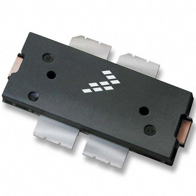
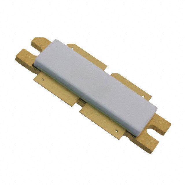
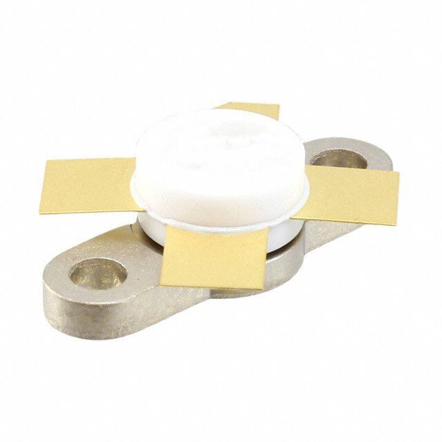
| 产品图片 |
|
| rohs | 符合RoHS无铅 / 符合限制有害物质指令(RoHS)规范要求 |
| 产品系列 | 晶体管,晶体管射频,射频MOSFET晶体管,MACOM MRF136- |
| 数据手册 | |
| 产品型号 | MRF136MRF136 |
| Pd-PowerDissipation | 55 W |
| Pd-功率耗散 | 55 W |
| Vds-Drain-SourceBreakdownVoltage | 65 V |
| Vds-漏源极击穿电压 | 65 V |
| Vgs-Gate-SourceBreakdownVoltage | +/- 40 V |
| Vgs-栅源极击穿电压 | +/- 40 V |
| Vgsth-Gate-SourceThresholdVoltage | 3 V |
| Vgsth-栅源极阈值电压 | 3 V |
| 产品种类 | 射频MOSFET晶体管 |
| 供应商器件封装 | 211-07, 2 型 |
| 其它名称 | 1465-1146 |
| 功率-输出 | 15W |
| 功率耗散 | 55 W |
| 包装 | 托盘 |
| 商标 | MACOM |
| 噪声系数 | 1dB |
| 增益 | 16 dB at 150 MHz16dB |
| 安装风格 | SMD/SMT |
| 封装 | Tray |
| 封装/外壳 | 211-07 |
| 封装/箱体 | Case 211-07 |
| 工厂包装数量 | 30 |
| 晶体管极性 | N-Channel |
| 晶体管类型 | N 通道 |
| 最大工作温度 | + 150 C |
| 最小工作温度 | - 65 C |
| 标准包装 | 20 |
| 汲极/源极击穿电压 | 65 V |
| 漏极连续电流 | 2.5 A |
| 电压-测试 | 28VDC |
| 电压-额定 | 65V |
| 电流-测试 | 25mA |
| 输出功率 | 15 W |
| 配置 | Single |
| 闸/源击穿电压 | +/- 40 V |
| 频率 | 400MHz400 MHz |
| 额定电流 | 2.5A |




- 商务部:美国ITC正式对集成电路等产品启动337调查
- 曝三星4nm工艺存在良率问题 高通将骁龙8 Gen1或转产台积电
- 太阳诱电将投资9.5亿元在常州建新厂生产MLCC 预计2023年完工
- 英特尔发布欧洲新工厂建设计划 深化IDM 2.0 战略
- 台积电先进制程称霸业界 有大客户加持明年业绩稳了
- 达到5530亿美元!SIA预计今年全球半导体销售额将创下新高
- 英特尔拟将自动驾驶子公司Mobileye上市 估值或超500亿美元
- 三星加码芯片和SET,合并消费电子和移动部门,撤换高东真等 CEO
- 三星电子宣布重大人事变动 还合并消费电子和移动部门
- 海关总署:前11个月进口集成电路产品价值2.52万亿元 增长14.8%

PDF Datasheet 数据手册内容提取
MRF136 The RF MOSFET Line 15W, to 400MHz, 28V Rev. V2 Product Image Designed for wideband large signal amplifier and oscillator applications Up to 400 MHz range, in single-ended configuration N–Channel enhancement mode . Guaranteed 28 volt, 150 MHz performance Output power = 15 watts Narrowband gain = 16 dB (Typ.) Efficiency = 60% (Typ.) Small– and large–signal characterization 100% tested for load mismatch at all phase angles with 30:1 VSWR Excellent thermal stability, ideally suited for Cass A operation Facilitates manual gain control, ALC and modulation techniques 111 M/A-COM Technology Solutions Inc. (MACOM) and its affiliates reserve the right to make changes to the product(s) or information contained herein without notice. Visit www.macom.com for additional data sheets and product information. For further information and support please visit: https://www.macom.com/support
MRF136 The RF MOSFET Line 15W, to 400MHz, 28V Rev. V2 222 M/A-COM Technology Solutions Inc. (MACOM) and its affiliates reserve the right to make changes to the product(s) or information contained herein without notice. Visit www.macom.com for additional data sheets and product information. For further information and support please visit: https://www.macom.com/support
MRF136 The RF MOSFET Line 15W, to 400MHz, 28V Rev. V2 333 M/A-COM Technology Solutions Inc. (MACOM) and its affiliates reserve the right to make changes to the product(s) or information contained herein without notice. Visit www.macom.com for additional data sheets and product information. For further information and support please visit: https://www.macom.com/support
MRF136 The RF MOSFET Line 15W, to 400MHz, 28V Rev. V2 444 M/A-COM Technology Solutions Inc. (MACOM) and its affiliates reserve the right to make changes to the product(s) or information contained herein without notice. Visit www.macom.com for additional data sheets and product information. For further information and support please visit: https://www.macom.com/support
MRF136 The RF MOSFET Line 15W, to 400MHz, 28V Rev. V2 555 M/A-COM Technology Solutions Inc. (MACOM) and its affiliates reserve the right to make changes to the product(s) or information contained herein without notice. Visit www.macom.com for additional data sheets and product information. For further information and support please visit: https://www.macom.com/support
MRF136 The RF MOSFET Line 15W, to 400MHz, 28V Rev. V2 666 M/A-COM Technology Solutions Inc. (MACOM) and its affiliates reserve the right to make changes to the product(s) or information contained herein without notice. Visit www.macom.com for additional data sheets and product information. For further information and support please visit: https://www.macom.com/support
MRF136 The RF MOSFET Line 15W, to 400MHz, 28V Rev. V2 777 M/A-COM Technology Solutions Inc. (MACOM) and its affiliates reserve the right to make changes to the product(s) or information contained herein without notice. Visit www.macom.com for additional data sheets and product information. For further information and support please visit: https://www.macom.com/support
MRF136 The RF MOSFET Line 15W, to 400MHz, 28V Rev. V2 888 M/A-COM Technology Solutions Inc. (MACOM) and its affiliates reserve the right to make changes to the product(s) or information contained herein without notice. Visit www.macom.com for additional data sheets and product information. For further information and support please visit: https://www.macom.com/support
MRF136 The RF MOSFET Line 15W, to 400MHz, 28V Rev. V2 999 M/A-COM Technology Solutions Inc. (MACOM) and its affiliates reserve the right to make changes to the product(s) or information contained herein without notice. Visit www.macom.com for additional data sheets and product information. For further information and support please visit: https://www.macom.com/support
MRF136 The RF MOSFET Line 15W, to 400MHz, 28V Rev. V2 111000 M/A-COM Technology Solutions Inc. (MACOM) and its affiliates reserve the right to make changes to the product(s) or information contained herein without notice. Visit www.macom.com for additional data sheets and product information. For further information and support please visit: https://www.macom.com/support
MRF136 The RF MOSFET Line 15W, to 400MHz, 28V Rev. V2 RF POWER MOSFET CONSIDERATIONS DESIGN CONSIDERATIONS resistive divider network. Some special applications may The MRF137 is a RF power N–Channel enhancement- require a more elaborate bias system. mode field–effect transistor (FET) designed especially for GAIN CONTROL VHF power amplifier applications. M/A-COM RF MOS Power output of the MRF137 may be controlled from FETs feature a vertical structure with a planar design, thus its rated value down to zero (negative gain) by varying the avoiding the processing difficulties associated with V– dc gate voltage. This feature facilitates the design of man- groove vertical power FETs. ual gain control, AGC/ALC and modulation systems. (See M/A-COM Application Note AN211A, FETs in Theory and- Figure 9.) Practice, is suggested reading for those not familiar with AMPLIFIER DESIGN the construction and characteristics of FETs. Impedance matching networks similar to those used The major advantages of RF power FETs include high with bipolar VHF transistors are suitable for MRF137. See gain, low noise, simple bias systems, relative immunity M/A-COM Application Note AN721, Impedance Matching from thermal runaway, and the ability to withstand severely Networks Applied to RF Power Transistors. The higher mismatched loads without suffering damage. Power output input impedance of RF MOS FETs helps ease the task of can be varied over a wide range with a low power dc con- broadband network design. Both small signal scattering trol signal, thus facilitating manual gain control, ALC and parameters and large signal impedances are provided. modulation. While the s–parameters will not produce an exact design solution for high power operation, they do yield a good first DC BIAS approximation. This is an additional advantage of RF MOS The MRF137 is an enhancement mode FET and, there- power FETs. fore, does not conduct when drain voltage is applied. Drain RF power FETs are triode devices and, therefore, not current flows when a positive voltage is applied to the gate. unilateral. This, coupled with the very high gain of the See Figure 10 for a typical plot of drain current versus gate MRF137, yields a device capable of self oscillation. Stabil- voltage. RF power FETs require forward bias for optimum ity may be achieved by techniques such as drain loading, performance. input shunt resistive loading, or output to input feedback. The value of quiescent drain current (IDQ) is not critical Two port parameter stability analysis with the MRF137 s– formany applications. The MRF137 was characterized at parameters provides a useful tool for selection of loading or IDQ = 25 mA, which is the suggested minimum value of IDQ. feedback circuitry to assure stable operation. See M/A- For special applications such as linear amplification, IDQ COM Application Note AN215A for a discussion of two port may have to be selected to optimize the critical parameters. network theory and stability. The gate is a dc open circuit and draws no current. There- fore, the gate bias circuit may generally be just a simple LOW NOISE OPERATION Input resistive loading will degrade noise performance, and noise figure may vary significantly with gate driving imped- ance. A low loss input matching network with its gate im- pedance optimized for lowest noise is recommended. 111111 M/A-COM Technology Solutions Inc. (MACOM) and its affiliates reserve the right to make changes to the product(s) or information contained herein without notice. Visit www.macom.com for additional data sheets and product information. For further information and support please visit: https://www.macom.com/support
MRF136 The RF MOSFET Line 15W, to 400MHz, 28V Rev. V2 111222 M/A-COM Technology Solutions Inc. (MACOM) and its affiliates reserve the right to make changes to the product(s) or information contained herein without notice. Visit www.macom.com for additional data sheets and product information. For further information and support please visit: https://www.macom.com/support
MRF136 The RF MOSFET Line 15W, to 400MHz, 28V Rev. V2 M/A-COM Technology Solutions Inc. All rights reserved. Information in this document is provided in connection with M/A-COM Technology Solutions Inc ("MACOM") products. These materials are provided by MACOM as a service to its customers and may be used for informational purposes only. Except as provided in MACOM's Terms and Conditions of Sale for such products or in any separate agreement related to this document, MACOM assumes no liability whatsoever. MACOM assumes no responsibility for errors or omissions in these materials. MACOM may make changes to specifications and product descriptions at any time, without notice. MACOM makes no commitment to update the information and shall have no responsibility whatsoever for conflicts or incompatibilities arising from future changes to its specifications and product descriptions. No license, express or implied, by estoppels or otherwise, to any intellectual property rights is granted by this document. THESE MATERIALS ARE PROVIDED "AS IS" WITHOUT WARRANTY OF ANY KIND, EITHER EXPRESS OR IMPLIED, RELATING TO SALE AND/OR USE OF MACOM PRODUCTS INCLUDING LIABILITY OR WARRANTIES RELATING TO FITNESS FOR A PARTICULAR PURPOSE, CONSEQUENTIAL OR INCIDENTAL DAMAGES, MERCHANTABILITY, OR INFRINGEMENT OF ANY PATENT, COPYRIGHT OR OTHER INTELLECTUAL PROPERTY RIGHT. MACOM FURTHER DOES NOT WARRANT THE ACCURACY OR COMPLETENESS OF THE INFORMATION, TEXT, GRAPHICS OR OTHER ITEMS CONTAINED WITHIN THESE MATERIALS. MACOM SHALL NOT BE LIABLE FOR ANY SPECIAL, INDIRECT, INCIDENTAL, OR CONSEQUENTIAL DAMAGES, INCLUDING WITHOUT LIMITATION, LOST REVENUES OR LOST PROFITS, WHICH MAY RESULT FROM THE USE OF THESE MATERIALS. MACOM products are not intended for use in medical, lifesaving or life sustaining applications. MACOM customers using or selling MACOM products for use in such applications do so at their own risk and agree to fully indemnify MACOM for any damages resulting from such improper use or sale. 111333 M/A-COM Technology Solutions Inc. (MACOM) and its affiliates reserve the right to make changes to the product(s) or information contained herein without notice. Visit www.macom.com for additional data sheets and product information. For further information and support please visit: https://www.macom.com/support
 Datasheet下载
