ICGOO在线商城 > MRA112
 Datasheet下载
- 型号: MRA112
- 制造商: NKK Switches
- 库位|库存: xxxx|xxxx
- 要求:
| 数量阶梯 | 香港交货 | 国内含税 |
| +xxxx | $xxxx | ¥xxxx |
查看当月历史价格
查看今年历史价格
MRA112产品简介:
ICGOO电子元器件商城为您提供MRA112由NKK Switches设计生产,在icgoo商城现货销售,并且可以通过原厂、代理商等渠道进行代购。 提供MRA112价格参考¥103.42-¥130.89以及NKK SwitchesMRA112封装/规格参数等产品信息。 你可以下载MRA112参考资料、Datasheet数据手册功能说明书, 资料中有MRA112详细功能的应用电路图电压和使用方法及教程。
| 参数 | 数值 |
| 3D型号 | http://www.nkkswitches.com/model.aspx?part=MRA112&vendor=digikey |
| 产品目录 | |
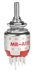
| 描述 | SW ROTARY SP 2-12POS PC 125V |
| 产品分类 | |
| 品牌 | NKK Switches |
| 数据手册 | |
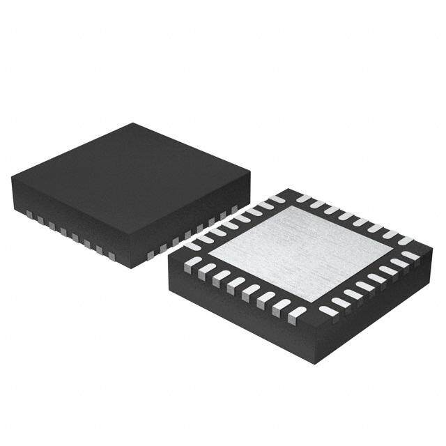
| 产品图片 |
|
| 产品型号 | MRA112 |
| rohs | 无铅 / 符合限制有害物质指令(RoHS)规范要求 |
| RoHS指令信息 | |
| 产品系列 | MR |
| 不同电压时的触头额定电流 | 0.25A @ 125VAC |
| 产品培训模块 | http://www.digikey.cn/PTM/IndividualPTM.page?site=cn&lang=zhs&ptm=7079http://www.digikey.cn/PTM/IndividualPTM.page?site=cn&lang=zhs&ptm=30248 |
| 其它名称 | 360-2584 |
| 安装类型 | 面板安装, 通孔 |
| 层数 | 1 |
| 抛射角 | 30° |
| 操作力,扭矩 | 0.02 ~ 0.07 N-m |
| 朝向 | 垂直 |
| 标准包装 | 1 |
| 每层极数 | 1 |
| 每层电路 | 单刀十二掷 |
| 特性 | 工艺密封 |
| 相关产品 | /product-detail/zh/AT4104C/360-2416-ND/2103593/product-detail/zh/AT4104B/360-2415-ND/2103592/product-detail/zh/AT4103A/360-2411-ND/1050657/product-detail/zh/AT4103B/360-2412-ND/1050652/product-detail/zh/AT4104A/360-2414-ND/1050643/product-detail/zh/AT4103C/360-2413-ND/1050512/product-detail/zh/AT433A/360-2410-ND/1050352 |
| 端子类型 | PC 引脚 |
| 致动器类型 | 扁平形(直径 3.17mm) |
| 致动器长度 | 10.00mm |
| 触头镀层 | 银 |
| 针脚数 | 2 ~ 12 |
| 面板开口尺寸 | 圆形 - 6.35mm 直径 |
| 额定电压-DC | - |
| 额定电流 | 250mA(AC) |


- 商务部:美国ITC正式对集成电路等产品启动337调查
- 曝三星4nm工艺存在良率问题 高通将骁龙8 Gen1或转产台积电
- 太阳诱电将投资9.5亿元在常州建新厂生产MLCC 预计2023年完工
- 英特尔发布欧洲新工厂建设计划 深化IDM 2.0 战略
- 台积电先进制程称霸业界 有大客户加持明年业绩稳了
- 达到5530亿美元!SIA预计今年全球半导体销售额将创下新高
- 英特尔拟将自动驾驶子公司Mobileye上市 估值或超500亿美元
- 三星加码芯片和SET,合并消费电子和移动部门,撤换高东真等 CEO
- 三星电子宣布重大人事变动 还合并消费电子和移动部门
- 海关总署:前11个月进口集成电路产品价值2.52万亿元 增长14.8%


PDF Datasheet 数据手册内容提取
Series MR Half-Inch Diameter Process Sealed Rotaries s e gl g General Specifications o T s er ck Electrical Capacity (Resistive Load) o R For MRA: 250mA @ 125V AC For MRF or MRK: 0.4VA maximum @ 28V AC/DC maximum s on (Applicable Range 0.1mA ~ 0.1A @ 20mV ~ 28V) utt Note: Find additional explanation of operating range in Supplement section. b h s u P Other Ratings B P d Contact Resistance: 10 milliohms maximum for MRA; 50 milliohms maximum for MRF & MRK e at Insulation Resistance: 100 megohms minimum @ 500V DC n mi Dielectric Strength: 1,000V AC minimum for 1 minute minimum for MRA u Ill 500V AC minimum for 1 minute minimum for MRF & MRK ble Mechanical Life: 30,000 operations minimum a m Electrical Life: 10,000 operations minimum m a Range of Operating Torque: 0.02 ~ 0.07Nm for MRA; 0.005 ~ 0.02Nm for MRF & MRK gr Pro Contact Timing: Nonshorting (break-before-make) MRA – self-cleaning, sliding contact; MRF & MRK – self-cleaning, rotary contactor disk ks Indexing: 30° c ylo e K Materials & Finishes Shaft: Brass with nickel plating s Stopper Plate: Steel with zinc plating for MRA & MRK; polyamide cover with stopper for MRF e ariG Bushing/Housing: Zinc alloy with zinc plating ot R Movable Contacts: Copper with silver plating for MRA; phosphor bronze with gold plating for MRF & MRK End Contacts & Terminals: Brass with silver plating for MRA; phosphor bronze with gold plating for MRF & MRK Common Contacts & Terminals: Brass with silver plating for MRA; phosphor bronze with gold plating for MRF & MRK es Base: Diallyl phthalate for MRA; fiberglass reinforced polyamide for MRF & MRK d Sli Environmental Data Operating Temperature Range: –10°C through +70°C (+14°F through +158°F) s actile VHiubmraitdioitny:: 9100 ~~ 9555%Hz h wumithid piteya fko-rt o9-6p ehaoku arsm @p li4tu0d°eC o(1f 014.5°mF)m traversing the frequency range & returning T in 1 minute; 3 right angled directions for 2 hours Shock: 50G (490m/s2) acceleration (tested in 3 right angled directions, with 3 shocks in each direction) Sealing: MRK model meets IP67 of IEC60529 standards Tilt Installation Mounting Torque: .686Nm (6.08 lb•in) Cap Installation Force: 19.6 ~ 29.4N (4.41 ~ 6.61 lbf) for MRA & MRK h c u o T Processing Soldering Time & Temperature: Wave Soldering for MRA: See Profile A in Supplement section. s or Wave Soldering for MRF & MRK: See Profile B in Supplement section. cat Manual Soldering for MRA: See Profile A in Supplement section. di n Manual Soldering for MRF & MRK: See Profile B in Supplement section. I Cleaning: Automated cleaning recommended. Stopper plate, as well as washers for MRA & MRK, must be in es place to maintain automated cleaning. See Cleaning specifications in Supplement section. sori s e cc Standards & Certifications A MRA, MRF, & MRK models have not been tested for UL recognition or CSA certification. nt These switches are designed for use in a low-voltage, low-current, logic-level circuit. e m e When used as intended in a logic-level circuit, the results do not produce hazardous energy. pl p u S G16 www.nkkswitches.com
Series MR Half-Inch Diameter Process Sealed Rotaries s e gl Distinctive Characteristics g o T s er k c o R Low profile body of MRF model accommodates space limitations required for PCB mounting. For the MRA and MRK bushing s n mount models, the range of behind panel body depths is .323” o utt to .669” (8.2mm to 17.0mm). b h s u P B P d Positive detent mechanism for distinct feel and audible feedback. e at n mi u Ill e Metal bushing and housing construction increases durability. bl a m m a gr o Adjustable stopper plate allows 2–12 position settings. Pr s k c o yl e High contact reliability achieved by the self-cleaning K contact mechanism. s e Gari ot R Break-before-make contact timing with sliding contacts in MRA and rotary contactor disk in MRF and MRK models. es d Sli Interior housing seal and molded-in PC terminals, plus shaft s rubber o-ring on MRA and MRK and polyamide cover on MRF ctile model, allow cleaning after automated soldering. Ta MRK model meets IP67 of IEC60529 specifications (similar to NEMA 4 & 13). Tilt Actual Size h c u o T s or at c di n I s e ori s s e c c A nt e m e pl p u S www.nkkswitches.com G17
Series MR Half-Inch Diameter Process Sealed Rotaries s e gl TYPICAL SWITCH ORDERING EXAMPLE g o T MR A 206 A s er k c o R s n o utt b h Actuators & Terminals Poles & Circuits Knobs Colors s u P A Shaft Actuated with PC Terminals 112 SP with 2-12 Positions A Plain Black For Plain Knob B P d Low Profile Screwdriver Actuated 206 DP with 2-6 Positions B Small Color Tipped No e F Black at with PC Terminals Code n 403 4P with 2-3 Positions C Large Color Tipped mi u Low Profile Shaft Actuated with For Color Tipped Ill K PC Terminals e A Black bl a m B White m a gr C Red o Pr DESCRIPTION FOR TYPICAL ORDERING EXAMPLE E Yellow ks MRA206-A F Green c o eyl G Blue K H Gray es Shaft Actuated with ariG Plain Black Knob ot R DP with 2-6 Adjustable Positions s e d Sli PC Terminals s e ctil a T ACTUATORS & TERMINALS Tilt Shaft Actuated Low Profile Low Profile A F K with PC Terminals Screwdriver Actuated Shaft Actuated with PC Terminals with PC Terminals h c u o T s Indicator 2 112 1211 1101 109 (2..(013.229.1280)) (3.5) 22311C4215121 6111M0711890R- (3.5) 211C2MR1112- 1K1101110299 (2..(013.229.1280)) (3.5) .138 (0.8) .138 .138 s .031 sorie (.1309.04) (0.5) ( 3.1.2154) Dia . 0(13.09) (0.5) (.1309.04) (0.5) s .020 .020 .020 e cc Thk = (0.25) Thk = (0.25) Thk = (0.25) A .010 .010 .010 nt me Shaft Terminal Slotted for Terminal Shaft Terminal e pl Screwdriver p u S G18 www.nkkswitches.com
Series MR Half-Inch Diameter Process Sealed Rotaries s e POLES & CIRCUITS gl g o T Pole Model Number of Positions Stopper Settings Number of Terminals Schematics A MRA112 2–12 2, 3, 4, . . . 12 1 COM, 12 LOAD s er SP MRF112 2–12 2, 3, 4, . . . 12 1 COM, 12 LOAD ck o R MRK112 2–12 2, 3, 4, . . . 12 1 COM, 12 LOAD 1 2 3 4 5 6 7 8 9 10 11 12 A B s MRA206 2–6 2, 3, 4, 5, 6 2 COM, 12 LOAD on utt DP MRF206 2–6 2, 3, 4, 5, 6 2 COM, 12 LOAD b h s MRK206 2–6 2, 3, 4, 5, 6 2 COM, 12 LOAD u P 1 2 3 4 5 6 1 2 3 4 5 6 B A B C D P MRA403 2–3 2, 3 4 COM, 12 LOAD d e 4P MRF403 2–3 2, 3 4 COM, 12 LOAD nat mi MRK403 2–3 2, 3 4 COM, 12 LOAD u 1 2 3 1 2 3 1 2 3 1 2 3 Ill e bl a m m POSITION SETTING FOR MRA, MRF, & MRK MODELS a gr o Pr Each switch is supplied with the stopper set for the maximum number of positions allowed for that model. Prior to installation, s the desired position setting should be made. Contact factory for continuous rotation. ck o yl e K MRF Models Protective Cover 1. Remove the protective cover from the switch body. es 2. Turn the shaft counterclockwise to the extreme left by using a screwdriver. Lens Gari Projection ot 3 . nsInnusamidpbepe etrhd we i nhctioocvh et hirse i stso wa b itmec hath,g etnh imefy apinxrgoim jleeucnmtiso pwno hbsiiectishoi dnwe ou tsuheledd ;lbe wen shp efiontss i tthiinoetn oce otdhv eeo rvc eoisrr rtthehecetn 22311C4215121 6111M0711890R- R hole for setting the stop. es d Sli MRK & MRA Models Standard Mounting Hardware s 1 . cUosuinngte trhcelo ackcwtuiaseto tro k tnhoeb e, xtutrrenm teh ele sfht.a fItf Packaged Loose with Each Switch: actile T the shaft is not turned counterclockwise Hex Face Nut to the extreme left, proper setting can- Locking Ring not be achieved. At this extreme posi- tion, the white line on the knob points Lockwasher Tilt to the number 1 position shown on the side of the switch. Rubber Ring (MRK) Factory Assembled: 2. Remove the knob from the shaft and h c loosen the nut far enough to allow rais- Hex Nut ou T ing the stopper plate, plus washer(s), for resetting to the desired position. Stopper Plate s 3. Note the position numbers on the side Metal Washer (MRA) ator of the switch; these correspond to the Rubber Washer dic terminal numbers and stopper holes. In Insert the stopper in the hole numbered s for the maximum desired number of e stop settings. Satisfactory switch func- sori s tioning cannot be assured if the stopper ce plate is not properly positioned. 211C2MR1112- 1K1101110299 12 11 10 9 Ac 2 1 12 11 10 nt 4. Tighten the nut (beveled side up) firmly e m against the stopper plate. ple p u S www.nkkswitches.com G19
Series MR Half-Inch Diameter Process Sealed Rotaries s e gl TYPICAL SWITCH DIMENSIONS g o T MRA • PC Terminals 1 Pole 2 Pole 4 Pole s er k oc (0.8) Dia Typ (3.0) Dia (3.0) Dia (3.0) Dia R M6 P0.75 .031 .118 .118 .118 buttons 01 119 182 A 7 1 6 2 5 3 4 4 5 3 62 AA 1 B 1 6 2 5 3 4 1 23 D 32 AA 1 B 1 3 2C 2 3 1 h (2.28) us Keyway .090 P B .(132.12) .(013.09) .(263.06) 30° Ty p 30° Ty p 30° Ty p ed P (.1663.00) Dia (.1309.40) (.519.07) (.1676.09) (.1309.40) (.93.754) Dia (.93.754) Dia (.93.754) Dia at n mi u Ill MRA112 e bl a m m MRF • PC Terminals 1 Pole 2 Pole 4 Pole a gr o Pr (0.8) (0.25) Typ .031 Cover .010 Keylocks 43526 7182191110 (.1427.20) Dia 01 1 1 2 19 8 A7 1 2 6 3 5 4 15° 30° 4 5 6 3 2 1 B A 1 2 6 3 5 4 15° 30° D 1 2 3 3 2 1 BA 1 2 3 3 2 1 C 15° 30° RotariesG ( 1 .45.501) Dia (.416.25) .(382.23) (.313.(.5080).250) Typ (.1429.66) D i1a5° Typ (.1429.66) D1ia5° Typ (.1429.66) Di1a5° Typ MRF403 s e d Sli MRK • PC Terminals 1 Pole 2 Pole 4 Pole (0.25) Typ Tactiles (2.28)M6 P0.75 .0(.114027.20) Dia 01 1 1 2 19 8 A7 1 2 6 3 5 4 15° 30° 4 5 6 3 2 1 B A 1 2 63 5 4 15° 30° D 1 2 3 3 2 1 AB 1 2 3 3 2 1 C 15° Typ .090 Tilt Keyway (.00.250) Typ 15° Typ 15° Typ 15° Typ (3.1) (10.0) (5.5) (10.1) (3.5) (12.6) Dia (12.6) Dia (12.6) Dia .122 .394 .217 .398 .138 .496 .496 .496 ch MRK112 MRK devices are designed to be panel mounted. Installation without panel mounting will affect reliability. u o T FOOTPRINTS s or at Single Pole Double Pole Four Pole Single Pole Double Pole Four Pole c di MRA112 MRA206 MRA403 MRF112 MRF206 MRF403 n I MRK112 MRK206 MRK403 s e Accessoriplement 34503° 6T2yAp7 1812911 .10(013.09) D(.31(.i193.a80.7 5)T4 yT) ypDpia 180°34503° 6Ty2Ap1 1B2635. 40(13.09) (.D31(.19i3.a80.7 5)T4 )Ty yDppia 90° 1320 33° C2TAy1p 1 B2D3321 .(013. 09)(. 31D(.913.8i0.a75)4 )TT yyDppia 30° Typ 1455°6 T3yp2 17A (.080.319821111)0 Di(.a142 7T.2y0p) Dia 30° Typ 1455°6 T3yp2 1BA1(.002.336815)4 Di(.a142 7T.2y0p) Dia 15° Typ 1C1253° T3y2p 1BA 1(.002.338312)D1 D(.i14a27 T.20yp) Dia p u S G20 www.nkkswitches.com
Series MR Half-Inch Diameter Process Sealed Rotaries s e KNOBS gl g o T AT433 AT4103 Small AT4104 Large A B C Plain Black Color Tipped Color Tipped s er k Material: Base Material: Base Material: oc R Polyacetal Polyester Polyester (18.0) Dia (19.0) Dia Base Color: (.1663.00) Dia Base Color: .709 Color: (.1714.08) Dia Black (.93.754) Dia Black (.1413.03) Dia ons Black .433 utt b only Polyamide Tip Polyamide Tip h (1.531.02) (9.5) Colors: (.1546.33) (9.5) Colors: (.1652.82) (9.5) Pus .374 A, B, C, E, F, G, H .374 A, B, C, E, F, G, H .374 B P (0.5) (0.5) (0.5) ed .020 .020 .020 at n mi u Ill A B C E F G H e Color Codes: Black White Red Yellow Green Blue Gray abl m m a PANEL CUTOUTS & MAXIMUM EFFECTIVE PANEL THICKNESS gr o Pr MRA & MRK MRK With Standard Hardware on Nonsealed Panel: ks c o Nonsealed Panel Sealed Panel MRA .067” (1.7mm) MRK .087” (2.2mm) eyl K Without With Without Locking Ring on Nonsealed Panel: Keyway Keyway (5.6) (6.2) Dia MRA .098” (2.5mm) MRK .118” (3.0mm) .220 .244 es (.62.5305) Dia .(265.56) (.62.5305) Dia .(002.64) (5.4) With AT513M & AT535 only on Sealed Panel: Gotari (2.2) Dia .213 MRK .106” (2.7mm) R .087 STANDARD MOUNTING HARDWARE s e d Sli AT513M AT545 AT509 AT535 Metric Hexagon Nut Locking Ring Lockwasher Rubber Ring Material: Material: Material: Material: es Brass, nickel plating Steel, chromate over zinc plating Steel, chromate over zinc plating Nitrile butadiene rubber ctil a 1 for MRA; 1 for MRK 1 for MRA; 1 for MRK 1 for MRA; 1 for MRK 1 for MRK T (5.5) .217 (6.0) M6 P0.75 .236 (.62.424) Dia Tilt (.83.105) (2.0) (.1415.67) (.62.542) Dia (.1400.22) Dia (.93.740) Dia .079 (12.0) .472 ch u o T (9.0) (1.5) (1.7) (0.8) (0.5) (1.3) .354 .059 .067 .031 .020 .051 s OPTIONAL SUPPORT BRACKET or at c di n AT543 I Support Bracket for MRK A support bracket s e MSteaetel rwiaitlh: tin plating (.1780.09) (.1780.09) iths en eMeRdKed i sw mhoenu n ted ssori (17.5) e (.1548.97) .689 only to a PC board Acc and does not have (.315.80) Typ (.00.250) Typ the bushing through ent (1.545.01) (.00.381) Typ (.1677.27) .(014.27) Dia Typ a panel. plem p u S www.nkkswitches.com G21
Mouser Electronics Authorized Distributor Click to View Pricing, Inventory, Delivery & Lifecycle Information: N KK Switches: MRK403-BF MRA403-A-RO MRA112-A-RO MRA206-A-RO MRA112-RO MRA112-BB-RO MRK112-A-RO MRK403-CA MRK206-CE MRA206-CE MRK403-BA MRK403-CH MRA112/208-BF