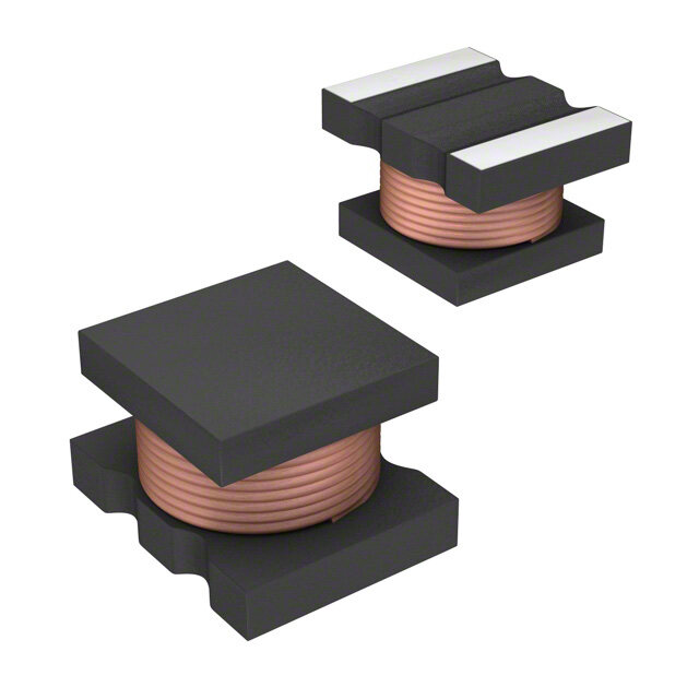
ICGOO在线商城 > 电感器,线圈,扼流圈 > 固定值电感器 > MPLC0730L4R7
- 型号: MPLC0730L4R7
- 制造商: Kemet
- 库位|库存: xxxx|xxxx
- 要求:
| 数量阶梯 | 香港交货 | 国内含税 |
| +xxxx | $xxxx | ¥xxxx |
查看当月历史价格
查看今年历史价格
MPLC0730L4R7产品简介:
ICGOO电子元器件商城为您提供MPLC0730L4R7由Kemet设计生产,在icgoo商城现货销售,并且可以通过原厂、代理商等渠道进行代购。 MPLC0730L4R7价格参考¥2.30-¥2.30。KemetMPLC0730L4R7封装/规格:固定值电感器, 4.7µH Shielded Wirewound Inductor 5A 41 mOhm Max 2-SMD, J-Lead。您可以下载MPLC0730L4R7参考资料、Datasheet数据手册功能说明书,资料中有MPLC0730L4R7 详细功能的应用电路图电压和使用方法及教程。
KEMET品牌的MPLC0730L4R7是一款固定值电感器,其主要应用场景包括以下几个方面:

1. 电源管理:该电感器适用于DC-DC转换器、开关电源(SMPS)和电压调节模块(VRM)中。它能够有效储存和释放能量,确保输出电压的稳定性,同时减少纹波电流。

2. 滤波电路:MPLC0730L4R7可用于电源滤波和信号滤波,帮助抑制电磁干扰(EMI)和射频干扰(RFI),从而提高电子设备的信号质量和抗干扰能力。

3. 通信设备:在无线通信模块、路由器和基站等设备中,这款电感器可用来匹配阻抗、滤除噪声并优化信号传输性能。

4. 消费电子产品:如平板电脑、智能手机、笔记本电脑和其他便携式设备中,MPLC0730L4R7可用于功率转换和滤波,支持高效能的电池管理和低功耗设计。

5. 工业自动化:在工业控制、传感器接口和电机驱动器中,这款电感器可以提供稳定的电流供应,确保系统运行的可靠性。

6. 汽车电子:适用于车载信息娱乐系统、导航设备和电源管理系统,满足汽车行业对高可靠性和耐久性的要求。

MPLC0730L4R7具有小型化设计、高饱和电流能力和低直流电阻的特点,适合需要紧凑空间和高效能的应用场合。此外,其良好的热稳定性和机械性能也使其能够在严苛环境下保持稳定工作。
| 参数 | 数值 |
| 产品目录 | |
| DC电阻(DCR) | 41 毫欧最大 |
| 描述 | FIXED IND 4.7UH 5A 41 MOHM SMD固定电感器 4.7uH 20% SMD |
| 产品分类 | |
| 品牌 | KemetKEMET NEC TOKIN |
| 产品手册 | |
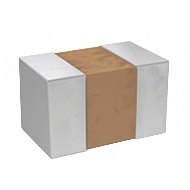
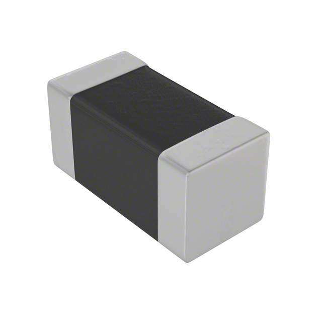
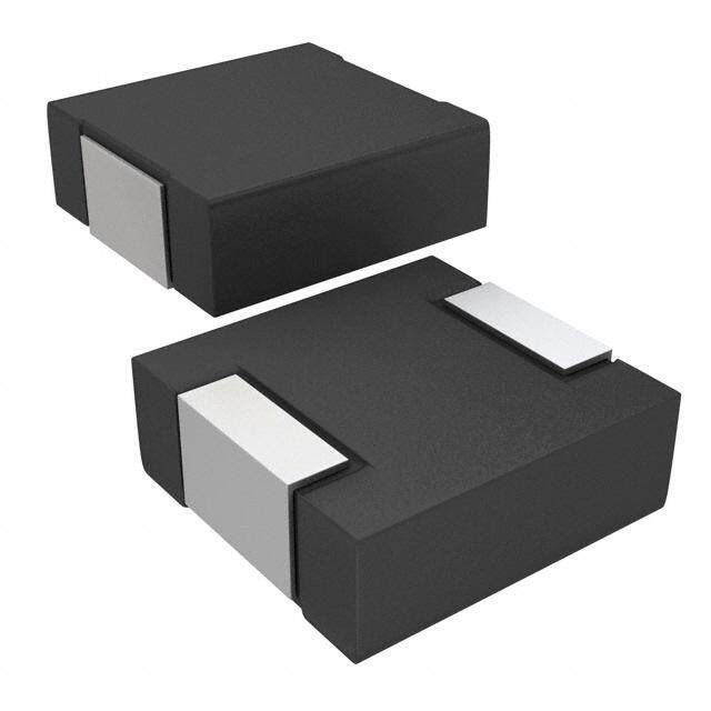
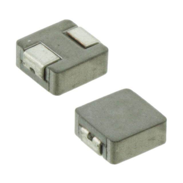
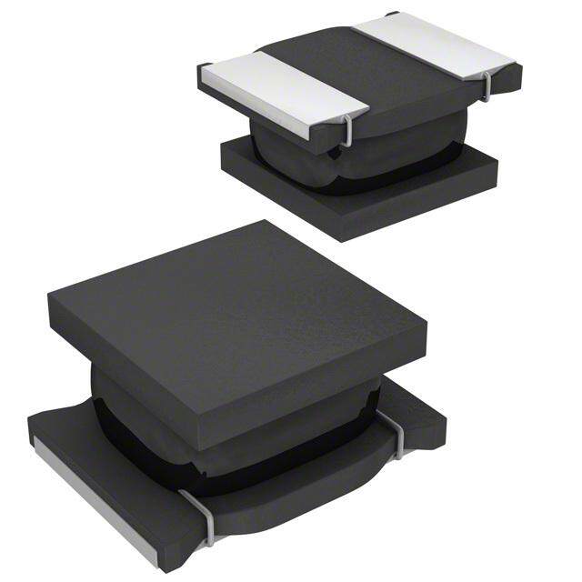
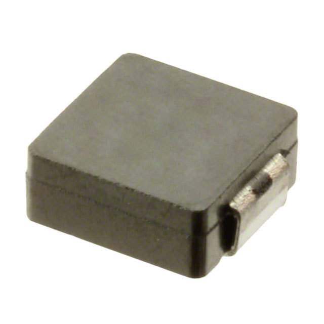
| 产品图片 |
|
| rohs | 符合RoHS无铅 / 符合限制有害物质指令(RoHS)规范要求 |
| 产品系列 | 固定电感器,KEMET NEC TOKIN MPLC0730L4R7MPLC |
| mouser_ship_limit | 该产品可能需要其他文件才能进口到中国。 |
| 数据手册 | http://www.kemet.com/docfinder?Partnumber=MPLC0730L4R7 |
| 产品型号 | MPLC0730L4R7MPLC0730L4R7 |
| 不同频率时的Q值 | - |
| 产品 | Large Current Power Inductors |
| 产品培训模块 | http://www.digikey.cn/PTM/IndividualPTM.page?site=cn&lang=zhs&ptm=30360 |
| 产品种类 | 固定电感器 |
| 供应商器件封装 | - |
| 其它名称 | 399-10992-6 |
| 包装 | Digi-Reel® |
| 商标 | KEMET NEC TOKIN |
| 外壳宽度 | 6.7 mm |
| 外壳长度 | 7.7 mm |
| 外壳高度 | 3 mm |
| 大小/尺寸 | 0.303" 长 x 0.264" 宽 (7.70mm x 6.70mm) |
| 安装类型 | 表面贴装 |
| 容差 | 20 %±20% |
| 封装 | Reel |
| 封装/外壳 | 非标准 |
| 屏蔽 | 无屏蔽 |
| 工作温度 | -20°C ~ 120°C |
| 工作温度范围 | - 20 C to + 120 C |
| 工厂包装数量 | 2000 |
| 最大直流电流 | 5 A |
| 最大直流电阻 | 41 mOhms |
| 材料-磁芯 | - |
| 标准包装 | 1 |
| 测试频率 | 100 kHz |
| 电感 | 4.7µH4.7 uH |
| 电流-饱和值 | 5.6A |
| 端接类型 | SMD/SMT |
| 类型 | 绕线Surface Mount Power Inductors |
| 系列 | MPLC |
| 频率-测试 | 100kHz |
| 频率-自谐振 | - |
| 额定电流 | 5A |
| 高度-安装(最大值) | 0.118"(3.00mm) |


- 商务部:美国ITC正式对集成电路等产品启动337调查
- 曝三星4nm工艺存在良率问题 高通将骁龙8 Gen1或转产台积电
- 太阳诱电将投资9.5亿元在常州建新厂生产MLCC 预计2023年完工
- 英特尔发布欧洲新工厂建设计划 深化IDM 2.0 战略
- 台积电先进制程称霸业界 有大客户加持明年业绩稳了
- 达到5530亿美元!SIA预计今年全球半导体销售额将创下新高
- 英特尔拟将自动驾驶子公司Mobileye上市 估值或超500亿美元
- 三星加码芯片和SET,合并消费电子和移动部门,撤换高东真等 CEO
- 三星电子宣布重大人事变动 还合并消费电子和移动部门
- 海关总署:前11个月进口集成电路产品价值2.52万亿元 增长14.8%

PDF Datasheet 数据手册内容提取
NOT FOR NEW DESIGN SMD Inductors Large-Current Power Inductors MPLC Overview The KEMET MPLC metal composite inductors offer large inductance values for use in DC to DC switching power supplies. These inductors offer superior permeability when compared to technologies based on ferrite cores. The round wire design allows for higher inductance compared to other wire designs. Applications • Switching DC-DC power supplies • Notebook computers • Tablets • Embedded computer systems • HDTVs • DVD and BluRay players Part Number System MPLC 0730 L 1R0 Series Size Code Inductor Inductance Code µH MPLC 0730 R = decimal point 1040 Example: 1R0 = 1.0 µH One world. One KEMET © KEMET Electronics Corporation • KEMET Tower • One East Broward Boulevard L9004_MPLC • 7/31/2018 1 Fort Lauderdale, FL 33301 USA • 954-766-2800 • www.kemet.com
SMD Type LLaarrggee--CCuurrrreenntt PPoowweerr IInndduuccttoorrss MMPPLLCC SSeerriieess [[RRooHHSS CCoommpplliiaanntt]] ・ Precautions (see page 80) Inductance Rated current(A) DC resistance Model at 100kHz, 1mA Irms *1 Isat *2 (μH) (mΩ) max. (Ref.) (Ref.) MPLC0730L1R0 1.0±20% 9.0 10.6 11.0 MPLC0730L1R5 1.5±20% 15.0 8.6 8.8 MPLC0730L2R2 2.2±20% 19.0 7.3 8.2 MPLC0730L3R3 3.3±20% 30.0 5.7 6.5 MPLC0730L4R7 4.7±20% 41.0 5.0 5.6 MPLC1040L1R0 1.0±20% 5.5 14.3 16.2 MPLC1040L1R5 1.5±20% 7.0 12.4 12.7 NOT FOR NEW DESIGN MPLC1040L2R2 2.2±20% 10.0 10.5 11.0 MPLC1040L3R3 3.3±20% 14.0 8.8 9.3 SMD InduMcPtoLCrs1040L4R7 4.7±20% 19.0 8.0 8.0 *L1 arTg=e40-KC ruisrer aetn ratt ePdo cuwrreenrt .I nd*u2c toInrdsuc MtanPceL dCrop 20% at rated current. ●Operating temperature range: -20~+120(cid:31) (Include self temperat ure rise) Table 1 – Ratings & Part Number Reference Shape and Dimensions Recommended Land Pattern ●MPPLaCr0t7 N30u Smerbieesr Inductance (µH) Inductance DC ResistaMnPcLeC 0730 Series Rated Current (A) at 100 kHz Tolerance (mΩ) Maxim●um Irms1 (Ref.) Isat2 (Ref.) 7.7 Maximum MMPPLLCC00773300LL11RR50 11..50 ±±2200%% 3.2 ±0.1 195..00 3.5 180..66 181..80 MPLC0730L6.7 ±0.22R2 2.2 ±20% 19.0 7.3 8.2 MPLC0730L3R3 3.3 ±20% 30.0 5.7 6.5 MPLC0730L4R7 4.7 ±20% 41.0 2.05.0 3.9 2.05.6 (1.4) MPLC1040L1R0 1.30.0 Maximum ±20% 5.5 14.3 16.2 ●MPLC1040 Series MPLC1040 Series MPLC1040L1R5 1.5 ±20% ●7.0 12.4 12.7 11.5 Maximum MPLC1040L2R2 2.2 ±20% 10.0 10.5 11.0 MPLC1040L3R3 3.3 ±20% 4.0 ±0.1 14.0 4.6 8.8 9.3 MPLC1040L10.0 ±0.24R7 4.7 ±20% 19S.0MD Type 8.0 8.0 1 T = 40 K rise at rated current. SMD Type 2 Inductance drop 20% at rated current. (2.1) [mm] 3.8 6.0 3.8 LLaarrggee--CCuurrrreenntt PPoowweerr IIn4n.0 Mddaximuuumccttoorrss MMPPLLLLaaCCrrg g SSeeee--rCrCiiueuersrsrreenntt PPoowweerr IInndduuccttoorrss SMD Type DDCMMC-S-uPPSpeuLrLppoCCese r dSpS Coheeasrrraeciidteee rsiCssthicsaracteristics SMD Type [[RRooHHSS CCoommpplliiaanntt]] LLaarrggee--CCuurrrreenntt PPoowweerr IInndduuccttoorrss [[RRooHHSS CCoommpplliiaaMLLnnPtata]]LrrCgg07ee3--0CC uurrrreenntt PPoowweerr IInndduuccttoorrss MPLC1040 5.0 MMPPLLCC SSeerriieess 5.0 ・ Precautions (see page 80) 4.5 MMPPLLCC SSeerriieess 4.5 ・ PMMMMMrecPPPPPaLLLLLutCCCCCion00000sM77777 (MMMMs33333oe00000PPPPde LLLLLLLLLpea11234CCCClgRRRRR0000eM 777705237803333o)0000 dInductance (µH)LLLLe1123lRRRR05231122334.......・・0505050 PPrree[[c[c[RaRaRRuuttioiooooonnssHHHH a(MM(ssteeSSPP SeSe1 LLpp 0 aaCC CgCgC0C00IeenM M a77k8811234ooo0o033tHdoo().....) 0005237md1mdmzmuLLee0,±±±±±μ11l cl0I1pRRHp22222pnpktm11230500000)Hldla(l....l%%%%%i0523Aiiziunaaa a,±±±±μ cc1nHn2222nntme0000)tattt%%%%A]]n]] ce 4aaRtt7 110000II3nnkk11RHdHd((..305zuzu,±±μ,μ c c11H22Htmtm00))Daa%%2AA(nCnR 2cc rmeDee(1134ΩCs159019i) Rsrm.....5e0000t0113aΩs 5909in)ms....c000t0aae xnm 1.cRae0x . DD((CC rrmmee1ΩsΩs59i)i)ss..0t0taa nmnmccaaeexx .. I(1rRm08755eI(1rR.f.... m0s6875.6370eInductance (µH)).f ...Rs6.637) *Ra1*1122334a t1.......e t0505050edd cI( 1I(rRrRcm0m8uee.f.ufs6.s6.r)) rrRRre**aea11n t tneet(t(dd AcAcI()I(1usRu)1sR1ear8865r1ea886 rfrf.t.....t....ee.0 08256 )825)nn**t(t(22 AAI(I()1)sRsR1ea8ea ff.t.t..0 8 ))**22 4R7 3R3 2R2 1R5 1R0 MMPPLLCC1100MM4400PPLLLL11CCRR0170053400LL41RR700.5 MMMMPPPPLLLLCCCC00007777113333..000005LLLL±±2311RR22RR41230500..%%70±±2200%% 2311....2305±±±±22220000%%%% 57..50415..05 1319059....0000 11421..4345..30 0.5 17508....3766 1116265....2726 18618....2508 MPLC10M40PLL2CR10240L1R50.00 MMMPPPLLLCCC0007772333.0002LLL±423R2RR17230.%55±20% 423...723±±±12220000%%% 10.07.0 15 413190...000 101.25.4 0.00 575...037 11152..07 586...625 10 15 20 MMPPLLCC1100MMM4400PPPLLLLL34CCCRR11100037444000LLL234RRR237 MMMMMMPPPPPPLLLLLLCCCCCC11101100070034444344..00000037LLLLLL±±112411RRR22RRR23405270500...%%237D±±±222C000 %%%Current (A)112411......052705±±±±±±222222 000000%%%%%% 1149..00111049...000 14057157......050050 881..08880...580 11111420425......345340 198198.....03030 D11111C621625 ......C270276urrent (A) *1 T=40K rise at rated current. *2 Inductance drop M2M0PP%LL aCCt 11ra00t44e0d0LL32RR32 current. 32..32±±2200%% 1140..00 180..85 191..30 ●Operating t*●eDOm1p peeriaTrat=mitn4ug0r Kete rremiasnpege naerta: tr uas-rtee2 dri0 ac~nougrre+e:n1 n 2-t.0 s2(cid:31)0 *(~I*n2c+1 l 1u2IdTn0e=d(cid:31) 4us 0(ceIKntl afrc inMsltMMueced emPPPae tdLLLp rsrCaeCCoetr1epl11afd 0t002t ce4044um%0r00rp eLLLaen4t34tr .arRRR at737t*ed2 Inductance udrreop r i2s0e%u)r aect u rrirasr434teee...n)d737t.±±± 222000%%% current. 111949...000 888...080 898...030 ●Operating temperature range: -20~+120(cid:31) (Include self temperat ure rise) Power Inductors VOL*.11 1T=40K rise at rated current. *2 Inductance drop 20% at rated current. ●Operating temperature range: -20~+120(cid:31) (Include self temperat ure rise) S●hMa1pP4eL aCnS0●dh7 MaD3p0iPme LS PaeCenn0radsi7e iD3ros0intm s SeNenrsiueiosmnsbeShrape and Dimensions Dimensions (mm) RecRMoemcPMoLmmPCeLm0nC7ed0n3e7d0d3e 0SLdR e aSeLrnceaLiodernmi sadePm sPanetantdtedteer ndrPn Laandt Ptaetterrnn 7.7 Maximu7m.7 MS●●ahxMMaimpPPuemLL aCCn00d77 3D300im SSeeenrrsiieeiossns7.7 Maximum ●● RecMM●omPPLLmCCe00n77d33e00d SSLeearrniiedes sPattern ●MPLC1●0M40P LSCe1ri0e4s06.7 ±0.2 MSerPieLs6.7 ±0.2C073●●0MMPPLLCC11004400 SS3ee.0rr iiMeeassx6.7 ±0.26.7 ±0.2im3u.0m Max1im71..7u5 m MMaaxxiimmuumm 33..00 MMaaxxiimmuumm3.2 ±0.1(1.4)3.2 ±0.1(1.4) 3.2 ±0.13.2 ±0.1((11M.●.44))PM●LCPL1C014004 S0e Sriee3.5rM●Msie3.5PPsLLCC11●00442.0002 .SS0eerriiee3.53.5ss 33.9.922..00 2233....0909 22..00 10.0 ±0.2MPL110.0 ±0.2C1.51 M0ax4im1u01m.5 Maximum 10.0 ±0.210.0 ±0.2 11.5 Maximum 4.0 Maximum4.0 ±0.1 4.0 ±0.1 4.0 ±0.14.0 ±0.1(2.1) [mm] 4.6●4.6 4.64.6 3.8 6.0 3.8 4.0 Maximum 4.0 Maximum(2.1)(2.1) [mm[]mm] (2.1) [mm] 3.83.8 66.0.03.8 336...880 3.8 DC-Superpos4e.0d MCahxaimraumcteristics DC-Superposed Characteristics ODCp-eSruapetripnogse tde Cmhapraecrteartisutirces range: −2M0P°LCC0 t7o30 + 120°C (Include self temperature riMsePL)C1040 DC-Superposed Characteristics 5.0 5.0 4.5MPLC0730 4.5MPLC1040 ©Fo rKtE L Inductance (µH)MauE12233445d........T50505050e MEr Inductance (µH)dlPeaLc0112233445lC..........e5050505050tr0,M o7FnP3LiL0 c3C s30 7C330o01r p UoSra4A Inductance (µH)RInductance (µH)t7 i•o001122334 001122334453.........9...........n05050505005050505050R30054 R•74 K-237RER236M61RE52-R2T28 T105R5DD5o0CCw CC•uue rrw1rrRree04 n4nwR•Rtt77 ((OAAw33))RRn3.3k1e1 0 0e 22ERRm22a1e1sRR55tt Inductance (µH). cBor11 12233445RRInductance (µH)o........m0050505050w11M501122334455a..........5050505050PrMdLC PB1LoC0u41l00e 4 Inductance (µH)Inductance (µH)v0a00112233400112233445r....................05050505005050505050d00 4R74R7553R33R3DDCC2 CCR22uuRrr2rree1114n04n0RR1Rt5t7R7 (5(AA33))RR33 1 R220RR22115511RR55 11RR002200 L9004_MPLC • 7/31/2018 2 1.0 0.0 1R0 1.0 0.0 1R0 0 5 10 15 0 5 10 15 20 0.5 0.5 Power InductoDrsC VCOuLrr.e1n1t (A) DC Current (A) 0.0 0.0 0 1P4owe5r Inductors VOL.1110 15 0 5 10 15 20 DC Current (A) DC Current (A) 14 Power Inductors VOL.11 14 Power Inductors VOL.11 14
NOT FOR NEW DESIGN SSMDM InDdu cTtoyrpse Large-Current Power Inductors MPLC Taping Specification MPLC0730 Series (1000pcs./reel) Dimensions of indented square hole plastic tape T P0 P2 D0 F E1 W F E1 P1 P2 P0 øD0 T[mm] REEL 0.3 0.1 0.1 0.1 0.1 0.1 0.05 0.05 24.0 11.5 1.75 16.0 2.0 4.0 1.55 0.4 Lot No.1R0L W SMD Type REEL P 1 Reel dimensions W [[mmmm]] 2 MPLC0730 Series (1000pcs./reel) Case Reel Dimensions (mAm ) B C D A 0 r W 1 W2 5.0 5.0 0.5 0.8 0.5 0.5 0.5 DiSmizenesionsQ ouAf0 ainndteitnyted squCaDre hole pWlastic tapFe E1 P1 P2ø380 P0 ø80øD0 øT13.5 ø21.0 2.0 R1.0 25.5 29.5 MPLC0730 1T,000 TNoPole0mrainnacle ±1B60..03 PA2 ±70.D5.01 1±.07.15 F1±20E..101 ±20.0.1 W±40.0.1 ±10.F5.055 ±00..045E1 P1 P2 P0 øD0 T[mm] REELTolerance ±0.3 ±0.1 ±0.1 ±0.1 ±0.1 0.3±0.1 ±00..015 ±0.050.1 0.1 0.1 0.1 0.05 0.05 MPLC1040 500 24.0 11.5 1.75 16.0 2.0 4.0 1.55 0.4 Nominal 24.0 11.5 1.75 16.0 2.0 4.0 1.55 0.4 W1 Lot No.1R0L W Reel SpecificatioREEnL s MPLC1040 Series (500pcs./reePl1) Reel dimensions Dimensions of indented square holeW plastic tape [[mmmm]] 2 P0 F A B C D A 0 r W 1 W[m2m] T P2 E1 5.0 5.0 0.5 0.8 0.5 0.5 0.5 A C D0 øW380 øF80 øE113.5 Pø121.0 P22.0 P0R1.0 øD025.5 T29.5 0 REEL D 0.3 0.1 0.1 0.1 0.1 0.1 0.05 0.05 B A 24.0 11.5 1.75 16.0 2.0 4.0 1.55 0.4 Lot No.1R0L W 3° REEL W 1 P1 Reel dimensions W2 [[mmmm]] Case Dimensions (mm) MPLC1040 Series (500pcs./reel) Size A B C D A A2.0r B1W.0 WC0.5 D0.8 A0.50 r W 2.10 W3.20 Dimensions oAfT0 ionledreanntceed squCa±r5e.0 hole p±la5s.0tic tap±e0.5 ±0.8 ±0.05 ø330 ø±810.10 ±ø1.1203.5 ø21.0 2.0 R1.0 24.4 30.4 MPLC0730T Nominal P0øD330 Bø80PA2 ø13.0 ø21.0F E12.0 R1.0 17.5 21.5 [mm] Tolerance ±2.0 ±1.0 D±00.5 ±0.8 ±0.5 W ±2.F0 ±3.0E1 P1 P2 P0 øD0 T MPLC1040 REEL 0.3 0.1 0.1 0.1 0.1 0.1 0.05 0.05 Nominal ø330 ø80 ø13.5 ø21.0 2.0 R1.0 24.4 30.4 24.0 11.5 1.75 16.0 2.0 4.0 1.55 0.4 W1 Lot No.1R0L W 3° REEL P1 Reel dimensions W2 [[mmmm]] A B C D A 0 r W 1 W2 2.0 1.0 0.5 0.8 0.5 2.0 3.0 A0 C ø330 ø80 ø13.5 ø21.0 2.0 R1.0 24.4 30.4 D B A © KEMET Electronics Corporation • KEMET Tower • One East Broward Boulevard L9004_MPLC • 7/31/2018 3 Fort Lauderdale, FL 33301 USA • 954-766-2800 • www.kemet.com W1 Power Inductors VOL.11 15 Power Inductors VOL.11 15
NOT FOR NEW DESIGN SMD Inductors Large-Current Power Inductors MPLC Handling Precautions Inductors should be stored in normal working environments. While the inductors themselves are quite robust in other environments, solderability will be degraded by exposure to high temperatures, high humidity, corrosive atmospheres, and long term storage. KEMET recommends that maximum storage temperature not exceed 40°C and maximum storage humidity not exceed 70% relative humidity. Atmospheres should be free of chlorine and sulfur bearing compounds. Temperature fluctuations should be minimized to avoid condensation on the parts. For optimized solderability, inductors’ stock should be used promptly, preferably within six months of receipt. Export Control For customers in Japan For products which are controlled items subject to the “Foreign Exchange and Foreign Trade Law” of Japan, the export license specified by the law is required for export. For customers outside Japan Inductors should not be used or sold for use in the development, production, stockpiling or utilization of any conventional weapons or mass-destruction weapons (nuclear, chemical, biological weapons or missiles), or any other weapons. © KEMET Electronics Corporation • KEMET Tower • One East Broward Boulevard L9004_MPLC • 7/31/2018 4 Fort Lauderdale, FL 33301 USA • 954-766-2800 • www.kemet.com
NOT FOR NEW DESIGN SMD Inductors Large-Current Power Inductors MPLC KEMET Electronics Corporation Sales Offi ces For a complete list of our global sales offi ces, please visit www.kemet.com/sales. Disclaimer All product specifi cations, statements, information and data (collectively, the “Information”) in this datasheet are subject to change. The customer is responsible for checking and verifying the extent to which the Information contained in this publication is applicable to an order at the time the order is placed. All Information given herein is believed to be accurate and reliable, but it is presented without guarantee, warranty, or responsibility of any kind, expressed or implied. Statements of suitability for certain applications are based on KEMET Electronics Corporation’s (“KEMET”) knowledge of typical operating conditions for such applications, but are not intended to constitute – and KEMET specifi cally disclaims – any warranty concerning suitability for a specifi c customer application or use. The Information is intended for use only by customers who have the requisite experience and capability to determine the correct products for their application. Any technical advice inferred from this Information or otherwise provided by KEMET with reference to the use of KEMET’s products is given gratis, and KEMET assumes no obligation or liability for the advice given or results obtained. Although KEMET designs and manufactures its products to the most stringent quality and safety standards, given the current state of the art, isolated component failures may still occur. Accordingly, customer applications which require a high degree of reliability or safety should employ suitable designs or other safeguards (such as installation of protective circuitry or redundancies) in order to ensure that the failure of an electrical component does not result in a risk of personal injury or property damage. Although all product–related warnings, cautions and notes must be observed, the customer should not assume that all safety measures are indicted or that other measures may not be required. KEMET is a registered trademark of KEMET Electronics Corporation. © KEMET Electronics Corporation • KEMET Tower • One East Broward Boulevard L9004_MPLC • 7/31/2018 5 Fort Lauderdale, FL 33301 USA • 954-766-2800 • www.kemet.com
Mouser Electronics Authorized Distributor Click to View Pricing, Inventory, Delivery & Lifecycle Information: K EMET: MPLC1040L2R2 MPLC0730L1R5 MPLC1040L3R3 MPLC1040L1R5 MPLC0730L2R2 MPLC1040L4R7 MPLC0730L3R3 MPLC0730L4R7 MPLC0730L1R0 MPLC0730LR75
 Datasheet下载

