ICGOO在线商城 > 射频/IF 和 RFID > RF 放大器 > MML20211HT1
- 型号: MML20211HT1
- 制造商: Freescale Semiconductor
- 库位|库存: xxxx|xxxx
- 要求:
| 数量阶梯 | 香港交货 | 国内含税 |
| +xxxx | $xxxx | ¥xxxx |
查看当月历史价格
查看今年历史价格
MML20211HT1产品简介:
ICGOO电子元器件商城为您提供MML20211HT1由Freescale Semiconductor设计生产,在icgoo商城现货销售,并且可以通过原厂、代理商等渠道进行代购。 MML20211HT1价格参考。Freescale SemiconductorMML20211HT1封装/规格:RF 放大器, 射频放大器 IC LTE,TDS-CDMA,W-CDMA 1.4GHz ~ 2.8GHz 8-DFN-EP(2x2)。您可以下载MML20211HT1参考资料、Datasheet数据手册功能说明书,资料中有MML20211HT1 详细功能的应用电路图电压和使用方法及教程。
NXP USA Inc.的MML20211HT1是一款射频(RF)放大器,广泛应用于无线通信系统中。该器件特别适用于需要高线性度和高效率的场景,如蜂窝基站、微波回传系统和无线基础设施设备。此外,MML20211HT1也常用于工业和商业级射频设备中,以增强信号传输能力和系统稳定性。
| 参数 | 数值 |
| 产品目录 | |
| 描述 | IC LNA 2GHZ 21P1DB 8DFN |
| 产品分类 | |
| 品牌 | Freescale Semiconductor |
| 数据手册 | |
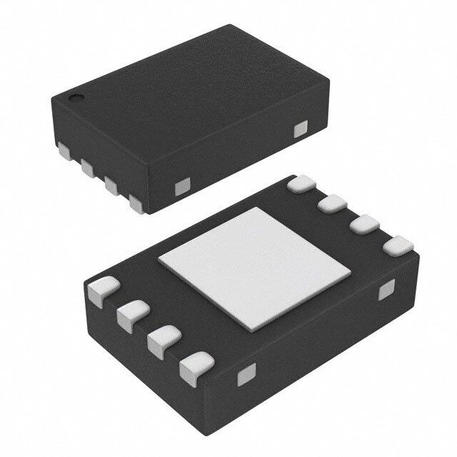
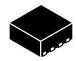
| 产品图片 |
|
| P1dB | 21.3dBm |
| 产品型号 | MML20211HT1 |
| RF类型 | LTE,TDS-CDMA,W-CDMA |
| rohs | 无铅 / 符合限制有害物质指令(RoHS)规范要求 |
| 产品系列 | - |
| 供应商器件封装 | 8-DFN-EP(2x2) |
| 其它名称 | MML20211HT1-ND |
| 包装 | 带卷 (TR) |
| 噪声系数 | 0.65dB |
| 增益 | 18.6dB |
| 封装/外壳 | 8-VFDFN 裸露焊盘 |
| 标准包装 | 1,000 |
| 测试频率 | 2.14GHz |
| 电压-电源 | 5V |
| 电流-电源 | 60mA |
| 频率 | 1.4GHz ~ 2.8GHz |






- 商务部:美国ITC正式对集成电路等产品启动337调查
- 曝三星4nm工艺存在良率问题 高通将骁龙8 Gen1或转产台积电
- 太阳诱电将投资9.5亿元在常州建新厂生产MLCC 预计2023年完工
- 英特尔发布欧洲新工厂建设计划 深化IDM 2.0 战略
- 台积电先进制程称霸业界 有大客户加持明年业绩稳了
- 达到5530亿美元!SIA预计今年全球半导体销售额将创下新高
- 英特尔拟将自动驾驶子公司Mobileye上市 估值或超500亿美元
- 三星加码芯片和SET,合并消费电子和移动部门,撤换高东真等 CEO
- 三星电子宣布重大人事变动 还合并消费电子和移动部门
- 海关总署:前11个月进口集成电路产品价值2.52万亿元 增长14.8%

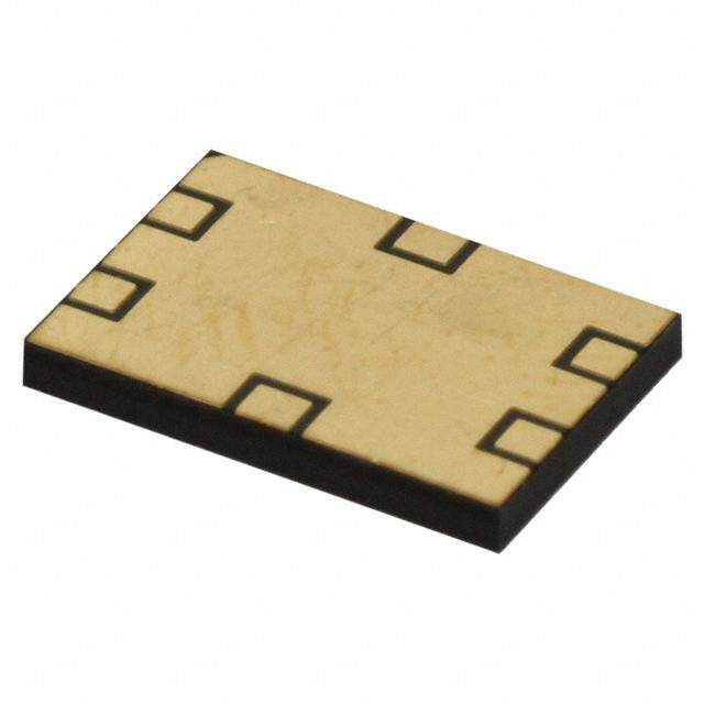

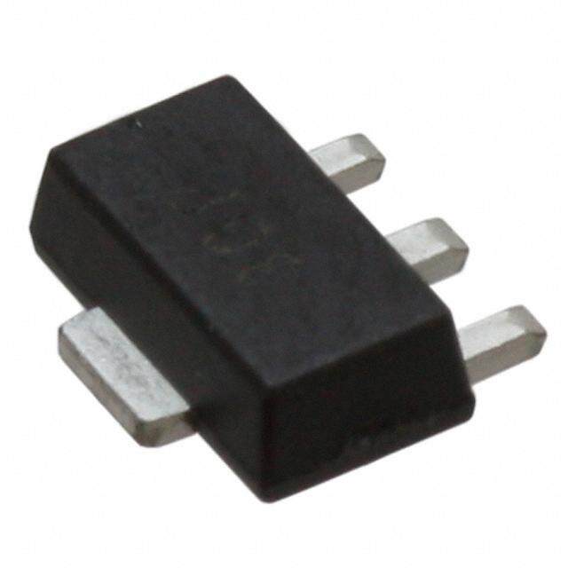
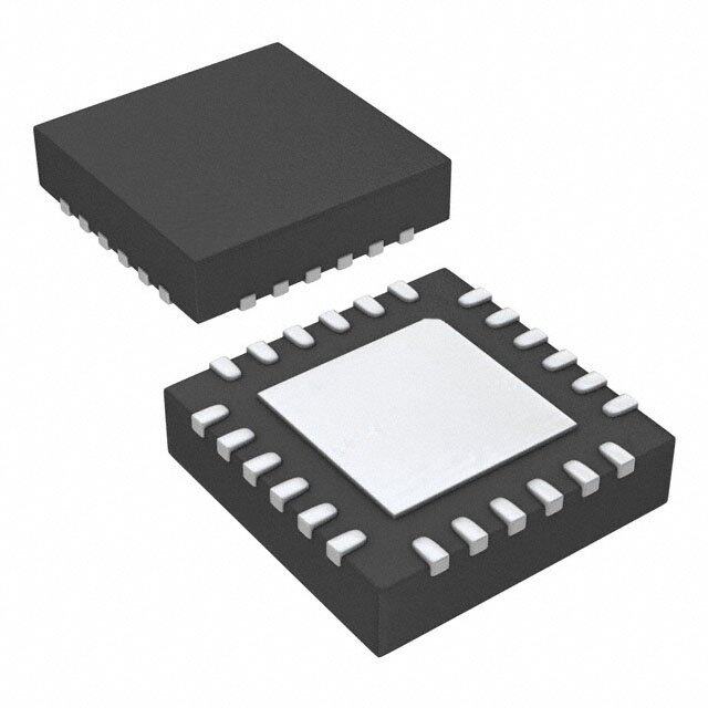
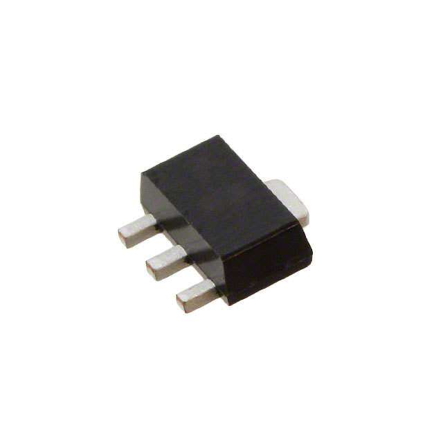

PDF Datasheet 数据手册内容提取
Freescale Semiconductor DocumentNumber:MML20211H Technical Data Rev.1,9/2014 Enhancement Mode pHEMT Technology (E--pHEMT) Low Noise Amplifier MML20211HT1 TheMML20211Hisasingle--stagelownoiseamplifier(LNA)withactivebias andhighisolationforuseincellularinfrastructureapplications.Itisdesignedfor arangeoflownoise,highlinearityapplicationssuchaspicocell,femtocell, towermountedamplifiers(TMA)andreceiverfrontendcircuits.Itoperatesfrom asinglevoltagesupplyandissuitableforapplicationswithfrequenciesfrom 1400to2800MHzsuchasTD--SCDMA,W--CDMA,UMTS,PCS,LTEandBWA. 1400--2800MHz,18.6dB 21.3dBm Features E--pHEMTLNA UltraLowNoiseFigure:0.65dB@2140MHz Frequency:1400--2800MHz HighReverseIsolation:--35dB@2140MHz P1dB:21.3dBm@2140MHz Small--SignalGain:18.6dB@2140MHz(adjustableexternally) ThirdOrderOutputInterceptPoint:33dBm@2140MHz ActiveBiasControl(adjustableexternally) Single5VSupply SupplyCurrent:60mA 50OhmOperation(someexternalmatchingrequired) DFN22 Cost--effective8--pin,2mmDFNSurfaceMountPlasticPackage InTapeandReel.T1Suffix=1,000Units,12mmTapeWidth,7--inchReel. Table1.TypicalPerformance(1) Table2.MaximumRatings 1400 1800 2140 2700 Rating Symbol Value Unit Characteristic Symbol MHz MHz MHz MHz Unit SupplyVoltage VDD 6 V NoiseFigure(2) NF 0.65 0.65 0.65 0.85 dB SupplyCurrent IDD 200 mA InputReturn IRL --19.5 --16 --16.7 --17.3 dB Loss(S11) RFInputPower Pin 22 dBm OutputReturn ORL --24.9 --28 --26.6 --20 dB StorageTemperatureRange Tstg --65to+150 C Loss(S22) JunctionTemperature TJ 175 C Small--Signal Gp 21.3 19.7 18.6 18.1 dB Gain(S21) PowerOutput P1dB 21.1 21.1 21.3 19.6 dBm @1dB Compression ThirdOrder IIP3 10.8 12.5 14.4 14.9 dBm InputIntercept Point ThirdOrder OIP3 32.1 32.2 33 33 dBm Output InterceptPoint 1. VDD=5Vdc,TA=25C,50ohmsystem,applicationcircuit tunedforspecifiedfrequency. 2. Noisefigurevaluecalculatedwithconnectorlossesremoved. Table3.ThermalCharacteristics Characteristic Symbol Value(3) Unit ThermalResistance,JunctiontoCase RJC 43.4 C/W CaseTemperature87C,5Vdc,IDD=60mA,noRFapplied 3. RefertoAN1955,ThermalMeasurementMethodologyofRFPowerAmplifiers.Gotohttp://www.freescale.com/rf. SelectDocumentation/ApplicationNotes--AN1955. FreescaleSemiconductor,Inc.,2011,2014.Allrightsreserved. MML20211HT1 RFDeviceData FreescaleSemiconductor 1
Table4.ElectricalCharacteristics(VDD=5Vdc,2140MHz,TA=25C,50ohmsystem,inFreescaleApplicationCircuit) Characteristic Symbol Min Typ Max Unit Small--SignalGain(S21) Gp 15 18.6 — dB InputReturnLoss(S11) IRL — --16.7 — dB OutputReturnLoss(S22) ORL — --26.6 — dB PowerOutput@1dBCompression P1dB — 21.3 — dBm ThirdOrderInputInterceptPoint IIP3 — 14.4 — dBm ThirdOrderOutputInterceptPoint OIP3 — 33 — dBm ReverseIsolation(S12) |S12| — --35 — dB NoiseFigure(1) NF — 0.65 — dB SupplyCurrent(2) IDD 45 60 85 mA SupplyVoltage VDD — 5 — V 1. Noisefigurevaluecalculatedwithconnectorlossesremoved. 2. DCcurrentmeasuredwithnoRFsignalapplied. Table5.FunctionalPinDescription Pin Number PinFunction 1 RFin RFin 1 8 N.C. 2 RFin RFin 2 7 RFout GND 3 RFInputMatchingTermination RFMATCH 3 6 RFout 4 BiasVoltageDCSupply VBIAS 4 5 FB 5 RFFeedback (TopView) 6 RFout/DCSupply 7 RFout/DCSupply Figure1.PinConnections 8 NoConnection Table6.ESDProtectionCharacteristics TestMethodology Class HumanBodyModel(perJESD22--A114) 0 MachineModel(perEIA/JESD22--A115) A ChargeDeviceModel(perJESD22--C101) IV Table7.MoistureSensitivityLevel TestMethodology Rating PackagePeakTemperature Unit PerJESD22--A113,IPC/JEDECJ--STD--020 1 260 C MML20211HT1 RFDeviceData 2 FreescaleSemiconductor
50OHMAPPLICATIONCIRCUIT:2140MHz VDD R3 C4 C8 C7 R2 RF Z6 INPUT C3 Z1 Z2 Z3 1 8 N.C. C1 L2 C9 2 7 RF OUTPUT Z4 Z5 L1 C2 3 6 C6 BIAS C5 R1 CIRCUIT 4 5 Z1 0.080x0.021Microstrip Z4 0.020x0.031Microstrip Z2 0.218x0.021Microstrip Z5 0.038x0.021Microstrip Z3 0.044x0.011Microstrip Z6 0.021x0.080Microstrip Figure2.MML20211HT1TestCircuitSchematic Table8.MML20211HT1TestCircuitComponentDesignationsandValues Part Description PartNumber Manufacturer C1,C5 18pFChipCapacitors GJM1555C1H180JB01D Murata C2,C3,C6,C7 18pFChipCapacitors GRM1555C1H180JA01D Murata C4,C8 0.1FChipCapacitors GRM155R61A104KA01D Murata C9 0.6pFChipCapacitor GJM1555C1HR60BB01D Murata L1,L2 3.6nHChipInductors 0402HP--3N6XGL Coilcraft R1 180,1/16WChipResistor RC0402FR--07180RL Yageo R2 0,1AChipResistor ERJ2GE0R00X Panasonic R3 1.5k,1/16WChipResistor RC0402FR--071K5L Yageo PCB 0.010,r=3.38,Multilayer IS680--3.38 Isola MML20211HT1 RFDeviceData FreescaleSemiconductor 3
50OHMAPPLICATIONCIRCUIT:2140MHz V D D 5 V C4 ViaA R3 RFIN RFOUT C9 C3 C1 L2 L1 C2 C6 C5 R2 R1 C7 C8 DFN2x2--8C ViaA Rev.0 NOTE:Toachieveoptimalnoiseperformance,itiscriticalthatproperbiasing,inputmatching,supply decouplingandgroundingareemployed. Figure3.MML20211HT1TestCircuitComponentLayout Table8.MML20211HT1TestCircuitComponentDesignationsandValues Part Description PartNumber Manufacturer C1,C5 18pFChipCapacitors GJM1555C1H180JB01D Murata C2,C3,C6,C7 18pFChipCapacitors GRM1555C1H180JA01D Murata C4,C8 0.1FChipCapacitors GRM155R61A104KA01D Murata C9 0.6pFChipCapacitor GJM1555C1HR60BB01D Murata L1,L2 3.6nHChipInductors 0402HP--3N6XGL Coilcraft R1 180,1/16WChipResistor RC0402FR--07180RL Yageo R2 0,1AChipResistor ERJ2GE0R00X Panasonic R3 1.5k,1/16WChipResistor RC0402FR--071K5L Yageo PCB 0.010,r=3.38,Multilayer IS680--3.38 Isola (TestCircuitComponentDesignationsandValuesrepeatedforreference.) MML20211HT1 RFDeviceData 4 FreescaleSemiconductor
50OHMTYPICALCHARACTERISTICS:2140MHz --3 -3-256 --6 -3-208 --9 -2-350 B) --12 B) -2-302 (d 85C (d 25C 1 2 1 --15 1 -1-354 S S --18 -1-306 --40C 25C --40C 85C --21 --358 VDD=5Vdc VDD=5Vdc --24 --400 2000 2060 2120 2180 2240 2300 2000 2060 2120 2180 2240 2300 f,FREQUENCY(MHz) f,FREQUENCY(MHz) Figure4.S11versusFrequencyversus Figure5.S12versusFrequencyversus Temperature Temperature 22 --19 21 --22 85C 20 --25 --40C 25C 25C B) 19 B) --28 d d ( ( 1 2 2 18 2 --31 S S 85C --40C 17 --34 16 --37 VDD=5Vdc VDD=5Vdc 15 --40 2000 2060 2120 2180 2240 2300 2000 2060 2120 2180 2240 2300 f,FREQUENCY(MHz) f,FREQUENCY(MHz) Figure6.S21versusFrequencyversus Figure7.S22versusFrequencyversus Temperature Temperature MML20211HT1 RFDeviceData FreescaleSemiconductor 5
50OHMTYPICALCHARACTERISTICS:2140MHz 1.4 22 21 1.2 20 B) 1 B) 19 (d 85C (d --40C E N 18 GUR 0.8 25C GAI 17 OISEFI 0.6 --40C POWER 16 25C 85C NF,N 0.4 G,ps 15 14 0.2 13 VDD=5Vdc VDD=5Vdc f=2140MHz 0 12 2040 2080 2120 2160 2200 2240 6 8 10 12 14 16 18 20 22 f,FREQUENCY(MHz) Pout,OUTPUTPOWER(dBm) Figure8.NoiseFigureversusFrequency Figure9.PowerGainversusOutputPower versusTemperature versusTemperature,CW m) m) B 38 B 36 d d ( ( OINT 36 OINT 35 P 34 P T T EP 32 EP 34 25C C C TER 30 TER 33 --40C N N I I T 28 T PU PU 32 85C T 26 T U U O O R 24 R 31 E E ORD 22 Vf=DD21=450VMdHcz ORD 30 VDD=5Vdc RD 20 1MHzToneSpacing RD 1MHzToneSpacing HI HI T 18 T 29 P3, 20 30 40 50 60 70 80 90 100 P3, 2040 2080 2120 2160 2200 2240 OI OI IDD,CURRENT(mA) f,FREQUENCY(MHz) Figure10.ThirdOrderOutputInterceptPoint Figure11.ThirdOrderOutputInterceptPoint (Two--Tone)versusIDDCurrent (Two--Tone)versusFrequencyversusTemperature 24 m) B d ( 23 W C T, --40C N 22 OI P ON 21 SI 85C S 25C RE 20 P M O C 19 B d B,1 18 P1d VDD=5Vdc 17 2040 2080 2120 2160 2200 2240 f,FREQUENCY(MHz) Figure12.P1dBversusFrequencyversus Temperature,CW MML20211HT1 RFDeviceData 6 FreescaleSemiconductor
50OHMAPPLICATIONCIRCUIT:1800MHz VDD R3 C4 C8 C7 R2 RF Z6 INPUT C3 Z1 Z2 Z3 1 8 N.C. C1 L2 C9 2 7 RF OUTPUT Z4 Z5 L1 C2 3 6 C6 BIAS C5 R1 CIRCUIT 4 5 Z1 0.080x0.021Microstrip Z4 0.020x0.031Microstrip Z2 0.218x0.021Microstrip Z5 0.038x0.021Microstrip Z3 0.044x0.011Microstrip Z6 0.021x0.080Microstrip Figure13.MML20211HT1TestCircuitSchematic Table9.MML20211HT1TestCircuitComponentDesignationsandValues Part Description PartNumber Manufacturer C1,C5 18pFChipCapacitors GJM1555C1H180JB01D Murata C2,C3,C6,C7 18pFChipCapacitors GRM1555C1H180JA01D Murata C4,C8 0.1FChipCapacitors GRM155R61A104KA01D Murata C9 0.7pFChipCapacitor GJM1555C1HR70BB01D Murata L1 3.6nHChipInductor 0402HP--3N6XGL Coilcraft L2 4.7nHChipInductor 0402CS--4N7 Coilcraft R1 180,1/16WChipResistor RC0402FR--07180RL Yageo R2 0,1AChipResistor ERJ2GE0R00X Panasonic R3 1.5k,1/16WChipResistor RC0402FR--071K5L Yageo PCB 0.010,r=3.38,Multilayer IS680--3.38 Isola MML20211HT1 RFDeviceData FreescaleSemiconductor 7
50OHMAPPLICATIONCIRCUIT:1800MHz V D D 5 V C4 ViaA R3 RFIN RFOUT C9 C3 C1 L2 L1 C2 C6 C5 R2 R1 C7 C8 ViaA DFN2x2--8C Rev.0 NOTE:Toachieveoptimalnoiseperformance,itiscriticalthatproperbiasing,inputmatching,supply decouplingandgroundingareemployed. Figure14.MML20211HT1TestCircuitComponentLayout Table9.MML20211HT1TestCircuitComponentDesignationsandValues Part Description PartNumber Manufacturer C1,C5 18pFChipCapacitors GJM1555C1H180JB01D Murata C2,C3,C6,C7 18pFChipCapacitors GRM1555C1H180JA01D Murata C4,C8 0.1FChipCapacitors GRM155R61A104KA01D Murata C9 0.7pFChipCapacitor GJM1555C1HR70BB01D Murata L1 3.6nHChipInductor 0402HP--3N6XGL Coilcraft L2 4.7nHChipInductor 0402CS--4N7 Coilcraft R1 180,1/16WChipResistor RC0402FR--07180RL Yageo R2 0,1AChipResistor ERJ2GE0R00X Panasonic R3 1.5k,1/16WChipResistor RC0402FR--071K5L Yageo PCB 0.010,r=3.38,Multilayer IS680--3.38 Isola (TestCircuitComponentDesignationsandValuesrepeatedforreference.) MML20211HT1 RFDeviceData 8 FreescaleSemiconductor
50OHMTYPICALCHARACTERISTICS:1800MHz --3 --3256 --6 --3208 --9 --2350 B) --12 B) --2302 d d ( ( 1 2 1 --15 1 --1354 S S --18 --1306 --21 --358 VDD=5Vdc VDD=5Vdc --24 --400 1650 1710 1770 1830 1890 1950 1650 1710 1770 1830 1890 1950 f,FREQUENCY(MHz) f,FREQUENCY(MHz) Figure15.S11versusFrequency Figure16.S12versusFrequency 22 --16 21 --19 20 --22 B) 19 B) --25 d d ( ( 1 2 2 18 2 --28 S S 17 --31 16 --34 VDD=5Vdc VDD=5Vdc 15 --37 1650 1710 1770 1830 1890 1950 1650 1710 1770 1830 1890 1950 f,FREQUENCY(MHz) f,FREQUENCY(MHz) Figure17.S21versusFrequency Figure18.S22versusFrequency MML20211HT1 RFDeviceData FreescaleSemiconductor 9
50OHMTYPICALCHARACTERISTICS:1800MHz m) 1.4 B 36 d ( T 1.2 OIN 35 P T B) 1 EP 34 d C ( R RE 0.8 TE 33 U N G I FI UT E 0.6 P 32 S T OI U N O NF, 0.4 DER 31 R 0.2 O 30 VDD=5Vdc VDD=5Vdc HIRD 1MHzToneSpacing 0 T 29 1700 1740 1780 1820 1860 1900 P3, 1700 1740 1780 1820 1860 1900 OI f,FREQUENCY(MHz) f,FREQUENCY(MHz) Figure19.NoiseFigureversusFrequency Figure20.ThirdOrderOutputInterceptPoint (Two--Tone)versusFrequency MML20211HT1 RFDeviceData 10 FreescaleSemiconductor
50OHMAPPLICATIONCIRCUIT:2700MHz VDD R3 C4 C8 C7 R2 RF Z5 INPUT Z1 Z2 C3 1 8 N.C. C1 L2 C9 2 7 RF OUTPUT Z3 Z4 L1 C2 3 6 BIAS C5 CIRCUIT 4 5 N.C. Z1 0.150x0.021Microstrip Z4 0.038x0.021Microstrip Z2 0.044x0.011Microstrip Z5 0.021x0.080Microstrip Z3 0.020x0.031Microstrip Figure21.MML20211HT1TestCircuitSchematic Table10.MML20211HT1TestCircuitComponentDesignationsandValues Part Description PartNumber Manufacturer C1,C5 8.2pFChipCapacitors GJM1555C1H8R2CB01 Murata C2,C3,C7 8.2pFChipCapacitors GRM1555C1H8R2DA01 Murata C4,C8 0.1FChipCapacitors GRM155R61A104KA01D Murata C6 ComponentNotPlaced C9 0.8pFChipCapacitor GJM1555C1HR80BB01D Murata L1,L2 2.2nHChipInductors 0402CS--2N2 Coilcraft R1 ComponentNotPlaced R2 0,1AChipResistor ERJ2GE0R00X Panasonic R3 1.5k,1/16WChipResistor RC0402FR--071K5L Yageo PCB 0.010,r=3.38,Multilayer IS680--3.38 Isola Note:ComponentnumbersC6andR1arelabeledonboardbutnotplaced. MML20211HT1 RFDeviceData FreescaleSemiconductor 11
50OHMAPPLICATIONCIRCUIT:2700MHz V D D 5 V C4 ViaA R3 RFIN RFOUT C9 C3 C1 L2 L1 C2 C6* C5 R2 R1* C7 C8 DFN2x2--8C ViaA Rev.0 Note:ComponentnumbersC6*andR1*arelabeledonboardbutnotplaced. NOTE:Toachieveoptimalnoiseperformance,itiscriticalthatproperbiasing,inputmatching,supply decouplingandgroundingareemployed. Figure22.MML20211HT1TestCircuitComponentLayout Table10.MML20211HT1TestCircuitComponentDesignationsandValues Part Description PartNumber Manufacturer C1,C5 8.2pFChipCapacitors GJM1555C1H8R2CB01 Murata C2,C3,C7 8.2pFChipCapacitors GRM1555C1H8R2DA01 Murata C4,C8 0.1FChipCapacitors GRM155R61A104KA01D Murata C6 ComponentNotPlaced C9 0.8pFChipCapacitor GJM1555C1HR80BB01D Murata L1,L2 2.2nHChipInductors 0402CS--2N2 Coilcraft R1 ComponentNotPlaced R2 0,1AChipResistor ERJ2GE0R00X Panasonic R3 1.5k,1/16WChipResistor RC0402FR--071K5L Yageo PCB 0.010,r=3.38,Multilayer IS680--3.38 Isola (TestCircuitComponentDesignationsandValuesrepeatedforreference.) MML20211HT1 RFDeviceData 12 FreescaleSemiconductor
50OHMTYPICALCHARACTERISTICS:2700MHz --3 --2365 --6 --2380 --9 --3205 B) --12 B) --3220 d d ( ( 1 2 1 --15 1 --3145 S S --18 --3160 --21 --385 VDD=5Vdc VDD=5Vdc --24 --400 2550 2610 2670 2730 2790 2850 2550 2610 2670 2730 2790 2850 f,FREQUENCY(MHz) f,FREQUENCY(MHz) Figure23.S11versusFrequency Figure24.S12versusFrequency 21 13 20 --16 19 --19 B) 18 B) --22 d d ( ( 1 2 2 17 2 --25 S S 16 --28 15 --31 VDD=5Vdc VDD=5Vdc 14 --34 2550 2610 2670 2730 2790 2850 2550 2610 2670 2730 2790 2850 f,FREQUENCY(MHz) f,FREQUENCY(MHz) Figure25.S21versusFrequency Figure26.S22versusFrequency MML20211HT1 RFDeviceData FreescaleSemiconductor 13
50OHMTYPICALCHARACTERISTICS:2700MHz m) 1.4 B 36 d ( T 1.2 OIN 35 P T B) 1 EP 34 d C ( R RE 0.8 TE 33 U N G I FI UT E 0.6 P 32 S T OI U N O NF, 0.4 DER 31 0.2 OR 30 VDD=5Vdc D 1MHzToneSpacing VDD=5Vdc HIR 0 T 29 2600 2640 2680 2720 2760 2800 P3, 2600 2640 2680 2720 2760 2800 OI f,FREQUENCY(MHz) f,FREQUENCY(MHz) Figure27.NoiseFigureversusFrequency Figure28.ThirdOrderOutputInterceptPoint (Two--Tone)versusFrequency MML20211HT1 RFDeviceData 14 FreescaleSemiconductor
2.00 0.80 0.30 0.50 1.60.8solderpadwith thermalviastructure.All 1.20 0.60 dimensionsinmm. 2.40 Figure29.PCBPadLayoutforDFN22 MB YW Figure30.ProductMarking MML20211HT1 RFDeviceData FreescaleSemiconductor 15
PACKAGEDIMENSIONS MML20211HT1 RFDeviceData 16 FreescaleSemiconductor
MML20211HT1 RFDeviceData FreescaleSemiconductor 17
MML20211HT1 RFDeviceData 18 FreescaleSemiconductor
PRODUCTDOCUMENTATION,TOOLSANDSOFTWARE Refertothefollowingresourcestoaidyourdesignprocess. ApplicationNotes AN1955:ThermalMeasurementMethodologyofRFPowerAmplifiers Software .s2pFile DevelopmentTools PrintedCircuitBoards For Software and Tools, do a Part Number search at http://www.freescale.com, and select the “Part Number” link. Go to Software&Toolsonthepart’sProductSummarypagetodownloadtherespectivetool. FAILUREANALYSIS Atthistime,becauseofthephysicalcharacteristicsofthepart,failureanalysisislimitedtoelectricalsignatureanalysis.In caseswhereFreescaleiscontractuallyobligatedtoperformfailureanalysis(FA)services,fullFAmaybeperformedbythird partyvendorswithmoderatesuccess.ForupdatescontactyourlocalFreescaleSalesOffice. REVISIONHISTORY Thefollowingtablesummarizesrevisionstothisdocument. Revision Date Description 0 Aug.2011 InitialReleaseofDataSheet 1 Sept.2014 Table2,MaximumRatings:updatedJunctionTemperaturefrom150Cto175Ctoreflectrecenttest resultsofthedevice,p.1 Table6,ESDProtectionCharacteristics:removedtheword“Minimum”aftertheESDclassrating.ESD ratingsarecharacterizedduringnewproductdevelopmentbutarenot100%testedduringproduction.ESD ratingsprovidedinthedatasheetareintendedtobeusedasaguidelinewhenhandlingESDsensitive devices,p.2 RevisedFailureAnalysisinformation,p.19 MML20211HT1 RFDeviceData FreescaleSemiconductor 19
HowtoReachUs: Informationinthisdocumentisprovidedsolelytoenablesystemandsoftware implementerstouseFreescaleproducts.Therearenoexpressorimpliedcopyright HomePage: licensesgrantedhereundertodesignorfabricateanyintegratedcircuitsbasedonthe freescale.com informationinthisdocument. WebSupport: Freescalereservestherighttomakechangeswithoutfurthernoticetoanyproducts freescale.com/support herein.Freescalemakesnowarranty,representation,orguaranteeregardingthe suitabilityofitsproductsforanyparticularpurpose,nordoesFreescaleassumeany liabilityarisingoutoftheapplicationoruseofanyproductorcircuit,andspecifically disclaimsanyandallliability,includingwithoutlimitationconsequentialorincidental damages.“Typical”parametersthatmaybeprovidedinFreescaledatasheetsand/or specificationscananddovaryindifferentapplications,andactualperformancemay varyovertime.Alloperatingparameters,including“typicals,”mustbevalidatedfor eachcustomerapplicationbycustomer’stechnicalexperts.Freescaledoesnotconvey anylicenseunderitspatentrightsnortherightsofothers.Freescalesellsproducts pursuanttostandardtermsandconditionsofsale,whichcanbefoundatthefollowing address:freescale.com/SalesTermsandConditions. FreescaleandtheFreescalelogoaretrademarksofFreescaleSemiconductor,Inc., Reg.U.S.Pat.&Tm.Off.Allotherproductorservicenamesarethepropertyoftheir respectiveowners. E2011,2014FreescaleSemiconductor,Inc. MML20211HT1 DocumentNumber:MML20211H RFDeviceData 2R0ev.1,9/2014 FreescaleSemiconductor
Mouser Electronics Authorized Distributor Click to View Pricing, Inventory, Delivery & Lifecycle Information: N XP: MML20211HT1
 Datasheet下载
