ICGOO在线商城 > 分立半导体产品 > 二极管 - 整流器 - 阵列 > MMBD1503-TP

 Datasheet下载
- 型号: MMBD1503-TP
- 制造商: MCC
- 库位|库存: xxxx|xxxx
- 要求:
| 数量阶梯 | 香港交货 | 国内含税 |
| +xxxx | $xxxx | ¥xxxx |
查看当月历史价格
查看今年历史价格
MMBD1503-TP产品简介:
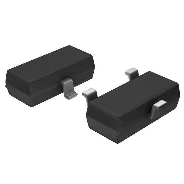
ICGOO电子元器件商城为您提供MMBD1503-TP由MCC设计生产,在icgoo商城现货销售,并且可以通过原厂、代理商等渠道进行代购。 MMBD1503-TP价格参考¥0.31-¥1.62。MCCMMBD1503-TP封装/规格:二极管 - 整流器 - 阵列, Diode Array 1 Pair Series Connection Standard 180V 200mA Surface Mount TO-236-3, SC-59, SOT-23-3。您可以下载MMBD1503-TP参考资料、Datasheet数据手册功能说明书,资料中有MMBD1503-TP 详细功能的应用电路图电压和使用方法及教程。
MMBD1503-TP 是由 Micro Commercial Co 提供的一款二极管整流器阵列,属于半导体分立器件。该型号的应用场景主要与其功能特性相关,具体如下:

 1. 电源管理
   - MMBD1503-TP 的核心功能是整流和保护,适用于各种电源管理电路。例如,在直流电源转换中,它可以将交流信号转换为直流信号,用于低功耗设备的供电。
   - 在电池充电电路中,它可以用作反向电流保护,防止电池在断电时向电路反向供电。

 2. 信号保护
   - 该二极管阵列可用于保护敏感电子设备免受过压、浪涌电流或静电放电(ESD)的影响。例如,在通信接口(如 RS-232 或 USB)中,它可以防止外部干扰对内部电路造成损坏。

 3. 数据通信
   - 在高速数据传输中,MMBD1503-TP 可以用作钳位二极管,限制信号电压范围,确保信号完整性。例如,在 CAN 总线或 I2C 通信中,它可以防止电压超出允许范围。

 4. 汽车电子
   - 汽车环境中存在大量电磁干扰和电压波动,MMBD1503-TP 可以用作保护元件,防止车载电子设备因瞬态电压而受损。例如,在汽车传感器、控制单元或照明系统中,它可以用作保护二极管。

 5. 消费电子产品
   - 在便携式设备(如智能手机、平板电脑或可穿戴设备)中,该器件可以用于电源输入保护或信号隔离,确保设备在复杂电磁环境下的稳定运行。

 6. 工业控制
   - 在工业自动化领域,MMBD1503-TP 可用于继电器驱动电路中的续流保护,防止感性负载引起的反向电动势损坏其他元件。
   - 它还可以用于电机控制电路中,提供过压保护和电流整流功能。

 总结
MMBD1503-TP 的应用场景广泛,涵盖了电源管理、信号保护、数据通信、汽车电子、消费电子和工业控制等领域。其小型化封装和高效性能使其成为现代电子设计中的理想选择。具体应用时需根据电路需求选择合适的外围元件,并确保工作条件符合器件规格书的要求。
| 参数 | 数值 |
| 产品目录 | |
| 描述 | DIODE ARRAY 180V 200MA SOT23二极管 - 通用,功率,开关 600mA 180V |
| 产品分类 | 二极管,整流器 - 阵列分离式半导体 |
| 品牌 | Micro Commercial Co |
| 产品手册 | |
| 产品图片 |
|
| rohs | 符合RoHS无铅 / 符合限制有害物质指令(RoHS)规范要求 |
| 产品系列 | 二极管与整流器,二极管 - 通用,功率,开关,Micro Commercial Components (MCC) MMBD1503-TP- |
| 数据手册 | |
| 产品型号 | MMBD1503-TP |
| 不同If时的电压-正向(Vf) | 1.3V @ 200mA |
| 不同 Vr时的电流-反向漏电流 | 10nA @ 180V |
| 二极管类型 | 标准 |
| 二极管配置 | 1 对串联 |
| 产品 | Switching Diodes |
| 产品培训模块 | http://www.digikey.cn/PTM/IndividualPTM.page?site=cn&lang=zhs&ptm=24932 |
| 产品目录绘图 |
|
| 产品目录页面 | |
| 产品种类 | 二极管 - 通用,功率,开关 |
| 供应商器件封装 | SOT-23 |
| 其它名称 | MMBD1503TP |
| 包装 | 带卷 (TR) |
| 反向恢复时间(trr) | - |
| 商标 | Micro Commercial Components (MCC) |
| 安装类型 | 表面贴装 |
| 安装风格 | SMD/SMT |
| 封装 | Reel |
| 封装/外壳 | TO-236-3,SC-59,SOT-23-3 |
| 封装/箱体 | SOT-23 |
| 峰值反向电压 | 200 V |
| 工作温度范围 | - 55 C to + 150 C |
| 工厂包装数量 | 3000 |
| 最大反向漏泄电流 | 0.01 uA |
| 最大工作温度 | + 150 C |
| 最大浪涌电流 | 2 A |
| 最小工作温度 | - 55 C |
| 标准包装 | 3,000 |
| 正向电压下降 | 1.5 V |
| 正向连续电流 | 0.2 A |
| 热阻 | 357°C/W Ja |
| 电压-DC反向(Vr)(最大值) | 180V |
| 电流-平均整流(Io)(每二极管) | 200mA |
| 系列 | MMBD15 |
| 速度 | 小信号 =< 200mA(Io),任意速度 |
| 配置 | Dual Series |


- 商务部:美国ITC正式对集成电路等产品启动337调查
- 曝三星4nm工艺存在良率问题 高通将骁龙8 Gen1或转产台积电
- 太阳诱电将投资9.5亿元在常州建新厂生产MLCC 预计2023年完工
- 英特尔发布欧洲新工厂建设计划 深化IDM 2.0 战略
- 台积电先进制程称霸业界 有大客户加持明年业绩稳了
- 达到5530亿美元!SIA预计今年全球半导体销售额将创下新高
- 英特尔拟将自动驾驶子公司Mobileye上市 估值或超500亿美元
- 三星加码芯片和SET,合并消费电子和移动部门,撤换高东真等 CEO
- 三星电子宣布重大人事变动 还合并消费电子和移动部门
- 海关总署:前11个月进口集成电路产品价值2.52万亿元 增长14.8%


PDF Datasheet 数据手册内容提取
M C C TM Micro Commercial Components 20736 Marilla Street, Chatsworth, CA91311 Tel:818-701-4933 Fax:818-701-4939 Process Change Notification st Jan-1 -2011 Subject : MCC Process Change Notification#PCN_010111 Title: MCC revise the pn# designation for MMBD1501A~MMBD1505A Effective Date : Apr-1st-2011 Reliability Data: Available per individual request Samples contact: Sales@mccsemi.com For question concerning this notification: techsupport@mccsemi.com Description and purpose : For our products MMBD1501~MMBD1505 has the same electrical & mechanical performances with MMBD1501A~MMBD1505A series, now in order to facilitate our customers to select our products more easier, we decide to combine them together and just use MBD1501~MMBD1505 as standard product from now on. This adjustment will not bring any function difference in the field application. www.mccsemi.com Rev.1-2011/01/01
M C C MMBD1501(A) (cid:1)(cid:2)(cid:3)(cid:4)(cid:5)(cid:6)(cid:7)(cid:5)(cid:8)(cid:8)(cid:9)(cid:4)(cid:3)(cid:2)(cid:10)(cid:11)(cid:6)(cid:7)omponents THRU TM 20736 Marilla Street Chatsworth Micro Commercial Components (cid:7)(cid:12)(cid:6)(cid:13)(cid:14)(cid:15)(cid:14)(cid:14) MMBD1505(A) (cid:16)(cid:17)(cid:5)(cid:18)(cid:9)(cid:19)(cid:6)(cid:20)(cid:21)(cid:14)(cid:21)(cid:22)(cid:6)(cid:23)(cid:24)(cid:14)(cid:25)(cid:26)(cid:13)(cid:15)(cid:15) (cid:27)(cid:10)(cid:28)(cid:19)(cid:6)(cid:6)(cid:6)(cid:20)(cid:21)(cid:14)(cid:21)(cid:22)(cid:6)(cid:23)(cid:24)(cid:14)(cid:25)(cid:26)(cid:13)(cid:15)(cid:13) Features High Conductance (cid:1) Low Leakage (cid:1) Surface Mount Package Ideally Suited for Auto Insertion Low Leakage Diode (cid:1) 150oC Junction Temperature (cid:1) Lead Free Finish/Rohs Compliant ("P"Suffix designates 350mW RoHS Compliant. See ordering information) M echanical Data SOT-23 (cid:1) Epoxy meets UL 94 V-0 flammability rating (cid:1) Moisture Sensitivity Level 1 A (cid:1) Polarity: See Diagram D (cid:1) Weight: 0.008 grams ( approx.) C B Maximum Ratings @ 25oC Unless Otherwise Specified F E Characteristic Symbol Value Unit Working Inverse Voltage VIV 180 V DC Forward Current IF 600 mA G H J Average Rectified Current Io 200 mA Recurrent Peak Forward Current if 700 mA K Peak Forward Surge Curren@t @t=t1=.10.m0ss if(surge) 12..00 A DIMENSIONS INCHES MM Power Dissipation Pd 350 mW DIM MIN MAX MIN MAX NOTE A .110 .120 2.80 3.04 Thermal R e s is t a n c e , J u n c t i o n t o A m b i e n t R θ J A 357 oC/W B .083 .104 2.10 2.64 C .047 .055 1.20 1.40 o Operation & Storage Temp. Range Tj, TSTG -55 to +150 C D .035 .041 .89 1.03 Note: 1)These ratings are based on a max. junction temperature of 150 degrees C E .070 .081 1.78 2.05 F .018 .024 .45 .60 2)These are steady state limits. Thefactory should be consulted on applications G .0005 .0039 .013 .100 involving pulsed or low duty cycle operation H .035 .044 .89 1.12 J .003 .007 .085 .180 Electrical Characteristics @ 25oC Unless Otherwise Specified K .015 .020 .37 .51 Suggested Solder Charateristic Symbol Min Max Unit Test Cond. Pad Layout Breakdown Voltage BV 200 V IR=5.0uA 620 750 mV IF=1.0mA ..083010 720 850 mV IF=10mA Forward Voltage Drop VF 800.803 915.10 m VV IIFF==15000mmAA ..093050 0.87 1.3 V IF=200mA .20.70900 inmchmes 0.9 1.5 V I =300mA F Reverse Current IR ----- 10 nA VR=180V ..093570 5.0 uA VR=180V TA=150oC .037 .950 Junction Capacitance Cj ----- 4 pF VR=0V, f=1.0MHz www.mccsemi.com Revision: A 1 o f 4 2011/01/01
M C C MMBD1501(A) thru MMBD1505(A) TM Micro Commercial Components REVERSE VOLTAGE vs REVERSE CURRENT Reverse Current Vs Reverse Voltage BV - 3.0 to 100 uA IR- 130 - 205 volts 325 A) 9 E (V) Ta= 25°C NT(n TA=25(cid:1082) AG RE 6 REVERSE VOLT237050 REVERSE CUR 3 V - R2503 5 10 20 30 50 100 VF I -R 0130 V1R5,0Reve1r7s0eVolt1a9g0e 210 GENERAL RULE: The Reverse Current of a diode will approximately I R - REVERSE CURRENT (uA) double for every ten (10) Degree C increase in Temperature FORWARD VOLTAGEvs FORWARD CURRENT CAPACITANCE vsREVERSE VOLTAGE VF - 10 to 800 mA VR - 0to15V 1.3 E (V)1.2 TA=25(cid:1) 4 Ta=25°C TAG1.1 pF)3.5 OL E ( 3 V1.0 C WARD 0.9 CITAN2.5 R PA 2 O0.8 A V - FF 0 C1.51 10 30 60 100 300 500700 0 2 4 6 8 10 12 14 15 II - FORWARDCURRENT (mA) REVERSE VOLTAGE (V) FF FORWARD VOLTAGE vs FORWARD CURRENT VF - 0.1 to 10 mA V)800 Ta= 25°C m E (750 G A LT700 O V D 650 R A W600 R O F550 V - F500 0.1 0.2 0.3 0.5 1 2 3 5 10 I F - FORWARD CURRENT (mA) www.mccsemi.com Revision: A 2 o f 4 2011/01/01
M C C MMBD1501(A) thru MMBD1505(A) TM Micro Commercial Components CONNECTION DIAGRAMS 1501 3 3 1503 3 11 1 2 NC 1 2 1504 3 3 1505 1 2 MARKING 1 2 1 2 MMBD1501(A) 11/A11 MMBD1503(A) 13/A13 MMBD1504(A) 14/A14 MMBD1505(A) 15/A15 www.mccsemi.com Revision: A 3 o f 4 2011/01/01
M C C TM Micro Commercial Components Ordering Information : Device Packing Part Number-TP Tape&Reel: 3Kpcs/Reel ***IMPORTANT NOTICE*** Micro Commercial Components Corp. reserves the right to make changes without further notice to any product herein to make corrections, modifications , enhancements , improvements , or other changes . Micro Commercial Components Corp . does not assume any liability arising out of the application or use of any product described herein; neither does it convey any license under its patent rights ,nor the rights of others . The user of products in such applications shall assume all risks of such use and will agree to hold Micro Commercial Components Corp . and all the companies whose products are represented on our website, harmless against all damages. ***LIFE SUPPORT*** MCC's products are not authorized for use as critical components in life support devices or systems without the express written approval of Micro Commercial Components Corporation. ***CUSTOMER AWARENESS*** Counterfeiting of semiconductor parts is a growing problem in the industry. Micro Commercial Components (MCC) is taking strong measures to protect ourselves and our customers from the proliferation of counterfeit parts. MCC strongly encourages customers to purchase MCC parts either directly from MCC or from Authorized MCC Distributors who are listed by country on our web page cited below. Products customers buy either from MCC directly or from Authorized MCC Distributors are genuine parts, have full traceability, meet MCC's quality standards for handling and storage. MCC will not provide any warranty coverage or other assistance for parts bought from Unauthorized Sources. MCC is committed to combat this global problem and encourage our customers to do their part in stopping this practice by buying direct or from authorized distributors. www.mccsemi.com 4 of 4 Revision: A 2011/01/01 3