ICGOO在线商城 > MLP2012HR54MT0S1

 Datasheet下载
- 型号: MLP2012HR54MT0S1
- 制造商: TDK
- 库位|库存: xxxx|xxxx
- 要求:
| 数量阶梯 | 香港交货 | 国内含税 |
| +xxxx | $xxxx | ¥xxxx |
查看当月历史价格
查看今年历史价格
MLP2012HR54MT0S1产品简介:
ICGOO电子元器件商城为您提供MLP2012HR54MT0S1由TDK设计生产,在icgoo商城现货销售,并且可以通过原厂、代理商等渠道进行代购。 提供MLP2012HR54MT0S1价格参考¥1.16-¥3.22以及TDKMLP2012HR54MT0S1封装/规格参数等产品信息。 你可以下载MLP2012HR54MT0S1参考资料、Datasheet数据手册功能说明书, 资料中有MLP2012HR54MT0S1详细功能的应用电路图电压和使用方法及教程。
| 参数 | 数值 |
| 产品目录 | |
| DC电阻(DCR) | 65 毫欧 |
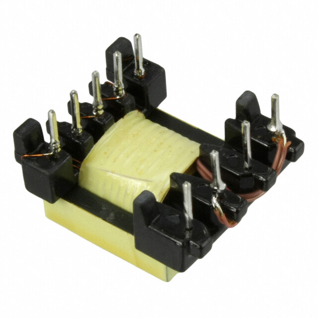
| 描述 | INDUCTOR POWER 540NH 20% 0805 |
| 产品分类 | |
| 品牌 | TDK Corporation |
| 数据手册 | |
| 产品图片 |
|
| 产品型号 | MLP2012HR54MT0S1 |
| rohs | 无铅 / 符合限制有害物质指令(RoHS)规范要求 |
| 产品系列 | MLP |
| 不同频率时的Q值 | - |
| 供应商器件封装 | 0805(2012 公制) |
| 其它名称 | 445-15717-2 |
| 包装 | 带卷 (TR) |
| 大小/尺寸 | 0.079" 长 x 0.049" 宽(2.00mm x 1.25mm) |
| 安装类型 | 表面贴装 |
| 容差 | ±20% |
| 封装/外壳 | 0805(2012 公制) |
| 屏蔽 | 无屏蔽 |
| 工作温度 | -40°C ~ 125°C |
| 材料-磁芯 | 铁氧体 |
| 标准包装 | 4,000 |
| 特色产品 | http://www.digikey.cn/product-highlights/zh/mlp-series-multilayer-ferrite-power-inductor/52962 |
| 电感 | 540nH |
| 电流-饱和值 | - |
| 类型 | 多层 |
| 频率-测试 | 2MHz |
| 频率-自谐振 | - |
| 额定电流 | 1.3A |
| 高度-安装(最大值) | 0.039"(1.00mm) |


.jpg)


- 商务部:美国ITC正式对集成电路等产品启动337调查
- 曝三星4nm工艺存在良率问题 高通将骁龙8 Gen1或转产台积电
- 太阳诱电将投资9.5亿元在常州建新厂生产MLCC 预计2023年完工
- 英特尔发布欧洲新工厂建设计划 深化IDM 2.0 战略
- 台积电先进制程称霸业界 有大客户加持明年业绩稳了
- 达到5530亿美元!SIA预计今年全球半导体销售额将创下新高
- 英特尔拟将自动驾驶子公司Mobileye上市 估值或超500亿美元
- 三星加码芯片和SET,合并消费电子和移动部门,撤换高东真等 CEO
- 三星电子宣布重大人事变动 还合并消费电子和移动部门
- 海关总署:前11个月进口集成电路产品价值2.52万亿元 增长14.8%


PDF Datasheet 数据手册内容提取
I N D U C T O R S Inductors for power circuits Cl Pb Br Multilayer ferrite MLP series RoHS SRVEHCA-CFrHee HaFlroegeen LFereaed MLP2012 type FEATURES A low-loss magnetic material is used so that a low-loss inductor for the power supply circuit can be achieved. In addition to the inductance value, product types with various features are available so that they can be compatible with different usages. H type: this product uses a low-loss material and has low DC resistance. * Optimal for when heavy load power efficiency is important. V type: as with the H type, this product with a low-loss magnetic material and that has good DC superimposition type characteristics. * Optimal for when light load power efficiency is important. S type: STD product lineup that includes a wide L value and various sizes. Operating temperature range: –40 to +125°C (including self-temperature rise) APPLICATION Smart phones, tablet terminals, digital cameras, video cameras, HDDs, power supply modules, etc. Application guides: Smart phones/tablets PART NUMBER CONSTRUCTION MLP 2012 H R47 M T 0S1 L×W×T dimensions Inductance Height Series name Characteristic type 0.55 mm max. Packaging style Internal code 2.0×1.25 mm (µH) 1.0 mm max. CHARACTERISTICS SPECIFICATION TABLE Type Thickness L Measuring DC resistance Rated current Part No. frequency T (mm)max. (µH) Tolerance (MHz) ()±30% (mA)max. 1.0 0.47 ±20% 2 0.07 1300 MLP2012HR47MT0S1 1.0 0.54 ±20% 2 0.065 1300 MLP2012HR54MT0S1 Low resistance 1.0 1.0 ±20% 2 0.12 1100 MLP2012H1R0MT0S1 1.0 1.5 ±20% 2 0.12 1100 MLP2012H1R5MT0S1 1.0 2.2 ±20% 2 0.15 1000 MLP2012H2R2MT0S1 Low core loss 0.55 1.0 ±20% 2 0.26 700 MLP2012V1R0TT0S1 1.0 0.47 ±20% 2 0.11 1100 MLP2012VR47MT0S1 Emphasized 1.0 1.0 ±20% 2 0.20 900 MLP2012V1R0MT0S1 DC bias 1.0 1.5 ±20% 2 0.23 800 MLP2012V1R5MT0S1 characteristics 1.0 2.2 ±20% 2 0.28 700 MLP2012V2R2MT0S1 1.0 4.7 ±20% 2 0.40 600 MLP2012V4R7MT0S1 Rated current: current assumed when temperature has risen to 40°C max. Measurement equipment Measurement item Product No. Manufacturer L 4294A+16034G Keysight Technologies DC resistance Type-7561 Yokogawa *Equivalent measurement equipment may be used. Please be sure to request delivery specifications that provide further details on the features and specifications of the products for proper and safe use. (1/9) Please note that the contents may change without any prior notice due to reasons such as upgrading. 20181207 inductor_commercial_power_mlp2012_en.fm
I N D U C T O R S MLP2012 type CHARACTERISTICS SPECIFICATION TABLE Type Thickness L Measuring DC resistance Rated current Part No. frequency T (mm)max. (µH) Tolerance (MHz) ()±30% (mA)max. 0.55 0.47 ±20% 2 0.13 1200 MLP2012SR47TT0S1 0.55 0.82 ±20% 2 0.13 1200 MLP2012SR82TT0S1 0.55 1.0 ±20% 2 0.23 800 MLP2012S1R0TT0S1 0.55 1.5 ±20% 2 0.27 700 MLP2012S1R5TT0S1 0.55 2.2 ±20% 2 0.33 600 MLP2012S2R2TT0S1 STD product 1.0 0.47 ±20% 2 0.09 1200 MLP2012SR47MT0S1 1.0 1.0 ±20% 2 0.16 1000 MLP2012S1R0MT0S1 1.0 1.5 ±20% 2 0.16 1000 MLP2012S1R5MT0S1 1.0 2.2 ±20% 2 0.23 800 MLP2012S2R2MT0S1 1.0 3.3 ±20% 2 0.19 900 MLP2012S3R3MT0S1 1.0 4.7 ±20% 2 0.26 700 MLP2012S4R7MT0S1 Rated current: current assumed when temperature has risen to 40°C max. Measurement equipment Measurement item Product No. Manufacturer L 4294A+16034G Keysight Technologies DC resistance Type-7561 Yokogawa *Equivalent measurement equipment may be used. Please be sure to request delivery specifications that provide further details on the features and specifications of the products for proper and safe use. (2/9) Please note that the contents may change without any prior notice due to reasons such as upgrading. 20181207 inductor_commercial_power_mlp2012_en.fm
I N D U C T O R S MLP2012 type (H characteristic product, T dimension of the product 1.0mm max.) L FREQUENCY CHARACTERISTICS 3.0 2.5 2.2µH 2.0 )H µ (e 1.5µH c n 1.5 a ct u nd 1.0µH I 1.0 0.54µH 0.5 0.47µH 0.0 0.1 1 10 100 Frequency(MHz) Measurement equipment Product No. Manufacturer 4294A+16034G Keysight Technologies *Equivalent measurement equipment may be used. INDUCTANCE VS. DC BIAS CHARACTERISTICS 3.0 2.5 2.2µH 2.0 )H µ (ce 1.5µH n 1.5 a ct u d n 1.0µH I 1.0 0.54µH 0.5 0.47µH 0.0 0 250 500 750 1000 1250 1500 DC current(mA) Measurement equipment Product No. Manufacturer 4285A+42841A+42842C+42851-61100 Keysight Technologies *Equivalent measurement equipment may be used. Please be sure to request delivery specifications that provide further details on the features and specifications of the products for proper and safe use. (3/9) Please note that the contents may change without any prior notice due to reasons such as upgrading. 20181207 inductor_commercial_power_mlp2012_en.fm
I N D U C T O R S MLP2012 type (V characteristic product, T dimension of the product 0.55mm max.) L FREQUENCY CHARACTERISTICS 3.0 2.5 2.0 )H µ (e c n 1.5 a ct u d n I 1.0 0.5 0.0 0.1 1 10 100 Frequency(MHz) Measurement equipment Product No. Manufacturer 4294A+16034G Keysight Technologies *Equivalent measurement equipment may be used. INDUCTANCE VS. DC BIAS CHARACTERISTICS 3.0 2.5 2.0 )H µ (e c n 1.5 a ct u d n I 1.0 0.5 0.0 0 200 400 600 800 1000 1200 DC current(mA) Measurement equipment Product No. Manufacturer 4285A+42841A+42842C+42851-61100 Keysight Technologies *Equivalent measurement equipment may be used. Please be sure to request delivery specifications that provide further details on the features and specifications of the products for proper and safe use. (4/9) Please note that the contents may change without any prior notice due to reasons such as upgrading. 20181207 inductor_commercial_power_mlp2012_en.fm
I N D U C T O R S MLP2012 type (V characteristic product, T dimension of the product 1.0mm max.) L FREQUENCY CHARACTERISTICS 7.0 6.0 5.0 4.7µH )H µ(e 4.0 c n a uct 3.0 d n I 2.2µH 2.0 1.5µH 1.0µH 1.0 0.47µH 0.0 0.1 1 10 100 Frequency(MHz) Measurement equipment Product No. Manufacturer 4294A+16034G Keysight Technologies *Equivalent measurement equipment may be used. INDUCTANCE VS. DC BIAS CHARACTERISTICS 5.0 4.5 4.7µH 4.0 3.5 )H 3.0 µ (e c n 2.5 a ct du 2.0 2.2µH n I 1.5 1.5µH 1.0 1.0µH 0.5 0.47µH 0.0 0 250 500 750 1000 1250 1500 DC current(mA) Measurement equipment Product No. Manufacturer 4285A+42841A+42842C+42851-61100 Keysight Technologies *Equivalent measurement equipment may be used. Please be sure to request delivery specifications that provide further details on the features and specifications of the products for proper and safe use. (5/9) Please note that the contents may change without any prior notice due to reasons such as upgrading. 20181207 inductor_commercial_power_mlp2012_en.fm
I N D U C T O R S MLP2012 type (S characteristic product, T dimension of the product 0.55mm max.) L FREQUENCY CHARACTERISTICS 3.0 2.5 2.2µH 2.0 )H µ(e 1.5µH c n 1.5 a ct u nd 1.0µH I 1.0 0.82µH 0.5 0.47µH 0.0 0.1 1 10 100 Frequency(MHz) Measurement equipment Product No. Manufacturer 4294A+16034G Keysight Technologies *Equivalent measurement equipment may be used. INDUCTANCE VS. DC BIAS CHARACTERISTICS 3.0 2.5 2.2µH 2.0 )H µ (e 1.5µH c n 1.5 a ct u d 1.0µH n I 1.0 0.82µH 0.5 0.47µH 0.0 0 200 400 600 800 1000 1200 DC current(mA) Measurement equipment Product No. Manufacturer 4285A+42841A+42842C+42851-61100 Keysight Technologies *Equivalent measurement equipment may be used. Please be sure to request delivery specifications that provide further details on the features and specifications of the products for proper and safe use. (6/9) Please note that the contents may change without any prior notice due to reasons such as upgrading. 20181207 inductor_commercial_power_mlp2012_en.fm
I N D U C T O R S MLP2012 type (S characteristic product, T dimension of the product 1.0mm max.) L FREQUENCY CHARACTERISTICS 6.0 5.0 4.7µH 4.0 )H µ(e 3.3µH c n 3.0 a ct du 2.2µH n I 2.0 1.5µH 1.0µH 1.0 0.47µH 0.0 0.1 1 10 100 Frequency(MHz) Measurement equipment Product No. Manufacturer 4294A+16034G Keysight Technologies *Equivalent measurement equipment may be used. INDUCTANCE VS. DC BIAS CHARACTERISTICS 6.0 5.0 4.7µH 4.0 )H µ (e 3.3µH c n 3.0 a ct u nd 2.2µH I 2.0 1.5µH 1.0µH 1.0 0.47µH 0.0 0 250 500 750 1000 1250 1500 DC current(mA) Measurement equipment Product No. Manufacturer 4285A+42841A+42842C+42851-61100 Keysight Technologies *Equivalent measurement equipment may be used. Please be sure to request delivery specifications that provide further details on the features and specifications of the products for proper and safe use. (7/9) Please note that the contents may change without any prior notice due to reasons such as upgrading. 20181207 inductor_commercial_power_mlp2012_en.fm
I N D U C T O R S MLP2012 type SHAPE & DIMENSIONS PACKAGING STYLE t=0.55mm t=1.0mm REEL DIMENSIONS 2.0±0.5 E 2.00±0.20 2.00±0.20 1.25±0.20 1.25±0.20 n. mi 0.50±0.05 0.85±0.20 ø60 0.50±0.30 1.0 0.50±0.30 Dimensions in mm ø13±0.2 8.4+–02..00 ø21±0.8 14.4max. ø180±2.0 Dimensions in mm TAPE DIMENSIONS MPZ2012 MPZ2012 RECOMMENDED LAND PATTERN (t=0.55) (t=t1.0) Shoplreocket 1.5+–00.1 2.0±0.05 4.0±0.1 1.75±0.1 3.5±0.05 3 0. ± 1.2 B 8.0 0.8 1.0 0.8 K K A 4.0±0.1 Cavity Dimensions in mm Dimensions in mm Type A B K t=0.55 1.5±0.2 2.3±0.2 0.8 max. MLP2012 t=1.0 1.5±0.2 2.3±0.2 1.1 max. 160min. Taping 200min. RECOMMENDED REFLOW PROFILE Preheating Soldering Natural cooling Drawing direction 300min. Peak Dimensions in mm 250 to 260°C PACKAGE QUANTITY e 230°C 230°C ur Package quantity 4000 pcs/reel at er p m e 180°C TEMPERATURE RANGE, INDIVIDUAL WEIGHT T 10s max. 150°C Type Operating Storage Individual temperature range temperature range weight t=0.55mm –40 to +125 °C –40 to +85 °C 7 mg 60 to 120s 30 to 60s t=1.0mm –40 to +125 °C –40 to +85 °C 10 mg Operating temperature range includes self-temperature rise. The storage temperature range is for after the assembly. Time Please be sure to request delivery specifications that provide further details on the features and specifications of the products for proper and safe use. (8/9) Please note that the contents may change without any prior notice due to reasons such as upgrading. 20181207 inductor_commercial_power_mlp2012_en.fm
I N D U C T O R S REMINDERS FOR USING THESE PRODUCTS Before using these products, be sure to request the delivery specifications. SAFETY REMINDERS Please pay sufficient attention to the warnings for safe designing when using this products. REMINDERS The storage period is less than 12 months. Be sure to follow the storage conditions (temperature: 5 to 40°C, humidity: 10 to 75% RH or less). If the storage period elapses, the soldering of the terminal electrodes may deteriorate. Do not use or store in locations where there are conditions such as gas corrosion (salt, acid, alkali, etc.). Before soldering, be sure to preheat components. The preheating temperature should be set so that the temperature difference between the solder temperature and chip temperature does not exceed 150°C. Soldering corrections after mounting should be within the range of the conditions determined in the specifications. If overheated, a short circuit, performance deterioration, or lifespan shortening may occur. When embedding a printed circuit board where a chip is mounted to a set, be sure that residual stress is not given to the chip due to the overall distortion of the printed circuit board and partial distortion such as at screw tightening portions. Self heating (temperature increase) occurs when the power is turned ON, so the tolerance should be sufficient for the set thermal design. Carefully lay out the coil for the circuit board design of the non-magnetic shield type. A malfunction may occur due to magnetic interference. Use a wrist band to discharge static electricity in your body through the grounding wire. Do not expose the products to magnets or magnetic fields. Do not use for a purpose outside of the contents regulated in the delivery specifications. The products listed on this catalog are intended for use in general electronic equipment (AV equipment, telecommunications equip- ment, home appliances, amusement equipment, computer equipment, personal equipment, office equipment, measurement equip- ment, industrial robots) under a normal operation and use condition. The products are not designed or warranted to meet the requirements of the applications listed below, whose performance and/or qual- ity require a more stringent level of safety or reliability, or whose failure, malfunction or trouble could cause serious damage to society, person or property. If you intend to use the products in the applications listed below or if you have special requirements exceeding the range or conditions set forth in the each catalog, please contact us. (1) Aerospace/aviation equipment (8) Public information-processing equipment (2) Transportation equipment (cars, electric trains, ships, etc.) (9) Military equipment (3) Medical equipment (10) Electric heating apparatus, burning equipment (4) Power-generation control equipment (11) Disaster prevention/crime prevention equipment (5) Atomic energy-related equipment (12) Safety equipment (6) Seabed equipment (13) Other applications that are not considered general-purpose (7) Transportation control equipment applications When designing your equipment even for general-purpose applications, you are kindly requested to take into consideration securing pro- tection circuit/device or providing backup circuits in your equipment. Please be sure to request delivery specifications that provide further details on the features and specifications of the products for proper and safe use. (9/9) Please note that the contents may change without any prior notice due to reasons such as upgrading. 20181207 inductor_commercial_power_mlp2012_en.fm
Mouser Electronics Authorized Distributor Click to View Pricing, Inventory, Delivery & Lifecycle Information: T DK: MLP2012S1R0T MLP2012S1R5T MLP2012S2R2T MLP2012SR47M MLP2012S1R0M MLP2012S1R5M MLP2012S2R2M MLP2012S3R3M MLP2012S4R7M MLP2012SR47T MLP2012SR82T MLP2012VR47M MLP2012V1R0M MLP2012HR47MT MLP2012V1R0TT MLP2012V4R7MT MLP2012H1R5MT MLP2012H2R2MT MLP2012H1R0MT MLP2012V2R2MT MLP2012HR54MT MLP2012V1R5MT MLP2012R1R0MT0S1 MLP2012S1R0MT0S1 MLP2012S2R2MT0S1 MLP2012S4R7MT0S1 MLP2012S3R3MT0S1 MLP2012SR47MT MLP2012S1R5MT0S1 MLP2012V1R0T MLP2012V1R5MT0S1 MLP2012H1R5MT0S1 MLP2012HR54MT0S1 MLP2012SR47MT0S1 MLP2012V4R7MT0S1 MLP2012VR47MT0S1 MLP2012V2R2MT0S1 MLP2012V1R0MT0S1 MLP2012S1R0TT0S1 MLP2012HR47MT0S1 MLP2012H1R0MT0S1 MLP2012H2R2MT0S1 MLP2012SR82TT0S1 MLP2012SR47TT0S1 MLP2012V1R0TT0S1 MLP2012S1R5TT0S1 MLP2012S2R2TT0S1