ICGOO在线商城 > 电感器,线圈,扼流圈 > 固定值电感器 > MLF1005A1R0KT
 Datasheet下载
- 型号: MLF1005A1R0KT
- 制造商: TDK
- 库位|库存: xxxx|xxxx
- 要求:
| 数量阶梯 | 香港交货 | 国内含税 |
| +xxxx | $xxxx | ¥xxxx |
查看当月历史价格
查看今年历史价格
MLF1005A1R0KT产品简介:
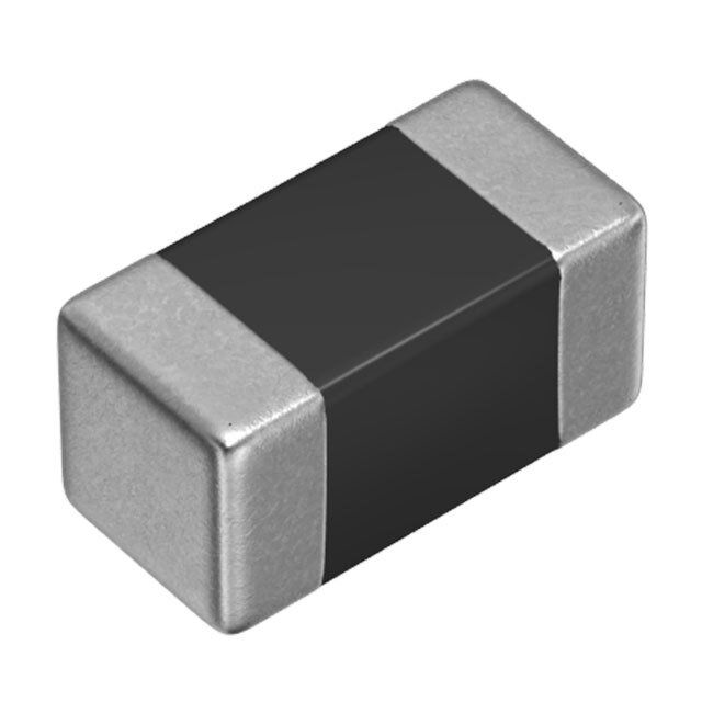
ICGOO电子元器件商城为您提供MLF1005A1R0KT由TDK设计生产,在icgoo商城现货销售,并且可以通过原厂、代理商等渠道进行代购。 MLF1005A1R0KT价格参考。TDKMLF1005A1R0KT封装/规格:固定值电感器, 1µH 屏蔽 多层 电感器 10mA 1 欧姆最大 0402(1005 公制) 。您可以下载MLF1005A1R0KT参考资料、Datasheet数据手册功能说明书,资料中有MLF1005A1R0KT 详细功能的应用电路图电压和使用方法及教程。
TDK Corporation的MLF1005A1R0KT是一款固定值电感器,具有紧凑的尺寸和稳定的性能,适用于多种电子设备中的高频应用。以下是其主要应用场景:

 1. 电源管理
MLF1005A1R0KT常用于开关电源(SMPS)和直流-直流转换器中,作为滤波电感器。它能够有效抑制高频噪声,确保电源输出的稳定性。由于其低电阻和高Q值特性,这款电感器能够在高频条件下保持高效的能量传输,减少能量损耗。

 2. 无线通信设备
在无线通信模块、蓝牙模块、Wi-Fi模块等高频电路中,MLF1005A1R0KT可用于匹配网络、滤波和阻抗调整。它有助于提高信号的完整性和传输效率,减少干扰,确保通信的可靠性。

 3. 消费电子产品
在智能手机、平板电脑、笔记本电脑等消费电子产品中,MLF1005A1R0KT可以用于电源管理芯片(PMIC)、音频放大器和其他高频电路中。它的小型化设计使其非常适合空间有限的便携式设备,同时保证了高性能和稳定性。

 4. 汽车电子
在汽车电子系统中,如车载信息娱乐系统、导航系统、雷达传感器等,MLF1005A1R0KT可以用于电源滤波和信号处理。它能够承受严苛的工作环境,并提供稳定的性能,确保汽车电子系统的可靠运行。

 5. 工业自动化
在工业控制系统、电机驱动器和传感器接口中,MLF1005A1R0KT可以用于滤波和信号调理。它的高耐热性和抗振性使其适合在工业环境中长期稳定工作,减少故障率。

 6. 物联网(IoT)设备
在物联网设备中,如智能家居控制器、智能穿戴设备等,MLF1005A1R0KT可以用于电源管理和信号处理。它的小尺寸和高效能使其成为这些小型化、低功耗设备的理想选择。

总之,MLF1005A1R0KT凭借其优异的高频性能、紧凑的设计和可靠的稳定性,广泛应用于各种需要高效能电感器的场景中。
| 参数 | 数值 |
| 产品目录 | |
| DC电阻(DCR) | 1 欧姆最大 |
| 描述 | INDUCTOR MULTILAYER 1.0UH 0402固定电感器 0402 1.0uH 10% |
| 产品分类 | |
| 品牌 | TDK |
| 产品手册 | |
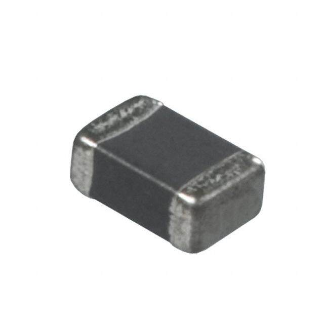
| 产品图片 |
|
| rohs | 符合RoHS无铅 / 符合限制有害物质指令(RoHS)规范要求 |
| 产品系列 | 固定电感器,TDK MLF1005A1R0KTMLF |
| 数据手册 | |
| 产品型号 | MLF1005A1R0KT |
| Q最小值 | 25 |
| 不同频率时的Q值 | 25 @ 10MHz |
| 产品 | Inductors |
| 产品培训模块 | http://www.digikey.cn/PTM/IndividualPTM.page?site=cn&lang=zhs&ptm=9295 |
| 产品目录绘图 |
|
| 产品目录页面 | |
| 产品种类 | 固定电感器 |
| 供应商器件封装 | 0402(1005 公制) |
| 其它名称 | 445-3514-6 |
| 其它图纸 |
|
| 包装 | Digi-Reel® |
| 商标 | TDK |
| 外壳宽度 | 0.5 mm |
| 外壳长度 | 1 mm |
| 外壳高度 | 0.5 mm |
| 大小/尺寸 | 0.039" 长 x 0.020" 宽(1.00mm x 0.50mm) |
| 安装类型 | 表面贴装 |
| 容差 | 10 % |
| 封装 | Reel |
| 封装/外壳 | 0402(1005 公制) |
| 封装/箱体 | 0402 (1005 metric) |
| 屏蔽 | Shielded |
| 工作温度 | -40°C ~ 85°C |
| 工作温度范围 | - 40 C to + 85 C |
| 工厂包装数量 | 10000 |
| 最大直流电流 | 10 mA |
| 最大直流电阻 | 1 Ohms |
| 材料-磁芯 | 铁氧体 |
| 标准包装 | 1 |
| 测试频率 | 10 MHz |
| 电感 | 1 uH |
| 电流-饱和值 | - |
| 端接类型 | SMD/SMT |
| 类型 | Multilayer Ferrite Inductor |
| 自谐振频率 | 120 MHz |
| 芯体材料 | Ferrite |
| 零件号别名 | MLF1005A1R0K |
| 频率-测试 | 10MHz |
| 频率-自谐振 | 120MHz |
| 额定电流 | 10mA |
| 高度-安装(最大值) | 0.022"(0.55mm) |


- 商务部:美国ITC正式对集成电路等产品启动337调查
- 曝三星4nm工艺存在良率问题 高通将骁龙8 Gen1或转产台积电
- 太阳诱电将投资9.5亿元在常州建新厂生产MLCC 预计2023年完工
- 英特尔发布欧洲新工厂建设计划 深化IDM 2.0 战略
- 台积电先进制程称霸业界 有大客户加持明年业绩稳了
- 达到5530亿美元!SIA预计今年全球半导体销售额将创下新高
- 英特尔拟将自动驾驶子公司Mobileye上市 估值或超500亿美元
- 三星加码芯片和SET,合并消费电子和移动部门,撤换高东真等 CEO
- 三星电子宣布重大人事变动 还合并消费电子和移动部门
- 海关总署:前11个月进口集成电路产品价值2.52万亿元 增长14.8%

PDF Datasheet 数据手册内容提取
(1/3) SMD Inductors(Coils) Conformity to RoHS Directive For Signal Line(Multilayer, Magnetic Shielded) MLF Series MLF1005 Various kinds of digital equipment are becoming smaller with more PRODUCT IDENTIFICATION advanced functions. Therefore, parts used in such digital MLF 1005 DR10 K T equipment need to be small and thinner. (1) (2) (3) (4) (5) MLFI005 Series inductors were developed to meet these demands. This series of inductors have 75% less mass than conventional MLF1608 inductors and are magnetically sealed just (1) Series name like conventional inductors, making high-density mounting possible. (2) Dimensions L×W 1005 1.0×0.5×0.5 FEATURES (cid:127) 75% less mass than the MLF1608 series. (3) Material code (cid:127) Magnetically sealed configuration allowing for high-density mounting. (4) Inductance value (cid:127) Does not contain lead and is compatible with lead-free R10 0.1µH soldering. 1R0 1.0µH (cid:127) It is a product conforming to RoHS directive. (5) Inductance tolerance APPLICATIONS K ±10% Signal processing modules such as mobile phones and tuners (6) Packaging style SPECIFICATIONS T Taping [reel] Operating temperature range –40 to +85°C Storage temperature range –40 to +85°C PACKAGING STYLE AND QUANTITIES Packaging style Quantity RECOMMENDED SOLDERING CONDITION Taping 10000 pieces/reel REFLOW SOLDERING HANDLING AND PRECAUTIONS (cid:127) Before soldering, be sure to preheat components. 10s max. The preheating temperature should be set so that the tempera- 250 to 260˚C Natural ture difference between the solder temperature and product 230˚C cooling temperature does not exceed 150°C. (cid:127) After mounting components onto the printed circuit board, do not 180˚C apply stress through board bending or mishandling. (cid:127) The inductance value may change due to magnetic saturation if 150˚C the current exceeds the rated maximum. Preheating Soldering (cid:127) Do not expose the inductors to stray magnetic fields. 60 to 120s 30 to 60s (cid:127) Avoid static electricity discharge during handling. Time(s) (cid:127) When hand soldering, apply the soldering iron to the printed cir- cuit board only. Temperature of the iron tip should not exceed 350°C. Soldering time should not exceed 3 seconds. (cid:127) Conformity to RoHS Directive: This means that, in conformity with EU Directive 2002/95/EC, lead, cadmium, mercury, hexavalent chromium, and specific bromine-based flame retardants, PBB and PBDE, have not been used, except for exempted applications. (cid:127) Please contact our Sales office when your application are considered the following: The device’s failure or malfunction may directly endanger human life (e.g. application for automobile/aircraft/medical/nuclear power devices, etc.) • All specifications are subject to change without notice. 002-04 / 20090402 / e511_mlf1005.fm
(2/3) SHAPES AND DIMENSIONS/RECOMMENDED PC BOARD PATTERN 1.0±0.05 5 0 0. ± 5 0. 0.1min. 0.1min. 0.5 0.4 0.5 5 0 0. 5 0.5± Dimensions in mm 0. Net weight : 1.2mg ELECTRICAL CHARACTERISTICS Test Test Self-resonant Inductance Inductance DC resistance Rated current Part No. frequency current Q min. frequency (µH) tolerance (Ω)max. (mA)max. L, Q (MHz) L, Q (mA) (MHz)min. MLF1005DR10K 0.1 ±10% 25 1.0 10 450 0.60 25 MLF1005DR12K 0.12 ±10% 25 1.0 10 400 0.70 25 MLF1005DR15K 0.15 ±10% 25 1.0 10 350 0.80 25 MLF1005DR18K 0.18 ±10% 25 1.0 10 320 0.90 25 MLF1005DR22K 0.22 ±10% 25 1.0 10 290 1.10 25 MLF1005DR27K 0.27 ±10% 25 1.0 10 260 1.30 25 MLF1005DR33K 0.33 ±10% 25 1.0 10 230 1.50 25 MLF1005AR39K 0.39 ±10% 10 1.0 25 210 0.60 10 MLF1005AR47K 0.47 ±10% 10 1.0 25 190 0.65 10 MLF1005AR56K 0.56 ±10% 10 1.0 25 170 0.70 10 MLF1005AR68K 0.68 ±10% 10 1.0 25 150 0.80 10 MLF1005AR82K 0.82 ±10% 10 1.0 25 130 0.90 10 MLF1005A1R0K 1.0 ±10% 10 1.0 25 120 1.00 10 MLF1005A1R2K 1.2 ±10% 10 1.0 25 110 1.10 10 MLF1005A1R5K 1.5 ±10% 10 1.0 25 100 1.30 10 MLF1005A1R8K 1.8 ±10% 10 1.0 25 90 1.55 10 MLF1005A2R2K 2.2 ±10% 10 1.0 25 80 1.80 10 ・Test equipment(L, Q): Ag-4294A or equivalent Test tool: Ag-16034G or equivalent TYPICAL ELECTRICAL CHARACTERISTICS INDUCTANCE vs. FREQUENCY CHARACTERISTICS 10 2.2µH )H 1 1.0µH µ (e c an 0.33µH ct u d In0.1 0.1µH 0.01 1 10 100 1000 10000 Frequency(MHz) Q vs. FREQUENCY CHARACTERISTICS IMPEDANCE vs. FREQUENCY CHARACTERISTICS 60 10000 0.33µH 50 2.2µH 1000 2.2µH 40 0.1µH Ω()e 1.0µH c Q 30 1.0µH dan100 0.33µH pe m 20 I 0.1µH 10 10 0 1 1 10 100 1000 10000 1 10 100 1000 10000 Frequency(MHz) Frequency(MHz) (cid:127) All specifications are subject to change without notice. 002-04 / 20090402 / e511_mlf1005.fm
(3/3) PACKAGING STYLES REEL DIMENSIONS 1.0 n. mi 0 6 ø 2.0±0.5 8.4+–02..00 ø13±0.2 14.4max. ø21±0.8 ø180±2.0 Dimensions in mm TAPE DIMENSIONS 1 5 Sprocket hole 1.5+–00..01 Cavity ±750.±50.0 1. 3. 3 0. ± 0 8. 1 0.8max. 0.65±0.1 4.0±0.1 0. ± 5 2.0±0.05 2.0±0.05 1.1 160min. Taping 200min. Drawing direction 300min. Dimensions in mm (cid:127) All specifications are subject to change without notice. 002-04 / 20090402 / e511_mlf1005.fm