.jpg)
 Datasheet下载
- 型号: ML03512R5BAT2A
- 制造商: AVX
- 库位|库存: xxxx|xxxx
- 要求:
| 数量阶梯 | 香港交货 | 国内含税 |
| +xxxx | $xxxx | ¥xxxx |
查看当月历史价格
查看今年历史价格
ML03512R5BAT2A产品简介:
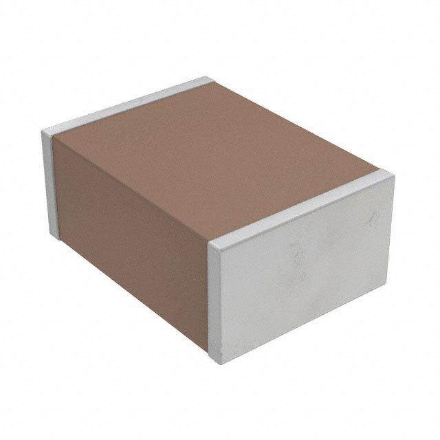
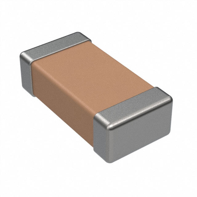
ICGOO电子元器件商城为您提供ML03512R5BAT2A由AVX设计生产,在icgoo商城现货销售,并且可以通过原厂、代理商等渠道进行代购。 ML03512R5BAT2A价格参考。AVXML03512R5BAT2A封装/规格:陶瓷电容器, 2.5pF ±0.1pF 50V 陶瓷电容器 C0G,NP0 0603(1608 公制)。您可以下载ML03512R5BAT2A参考资料、Datasheet数据手册功能说明书,资料中有ML03512R5BAT2A 详细功能的应用电路图电压和使用方法及教程。
AVX Corporation生产的型号为ML03512R5BAT2A的陶瓷电容器属于多层陶瓷电容器(MLCC,Multilayer Ceramic Capacitor)系列。其应用场景广泛,主要集中在电子设备中的滤波、耦合、去耦、旁路以及信号调谐等方面。以下是具体的应用场景分析:

 1. 电源电路中的滤波与去耦
   - 功能:该型号电容器可用于电源电路中,提供高频噪声滤波和去耦功能,确保电路中的电压稳定。
   - 应用领域:适用于消费电子(如智能手机、平板电脑)、工业控制设备、通信基站等。

 2. 信号处理中的耦合与旁路
   - 功能:在信号传输过程中,用于隔离直流成分,同时允许交流信号通过(耦合)。此外,还可以作为旁路电容,消除高频干扰。
   - 应用领域:音频设备、射频模块、无线通信设备等。

 3. 高频电路中的性能优化
   - 功能:由于其低ESR(等效串联电阻)和低ESL(等效串联电感),适合用于高频电路中,以提高信号完整性和减少电磁干扰(EMI)。
   - 应用领域:5G通信设备、雷达系统、物联网(IoT)设备等。

 4. 汽车电子中的可靠保障
   - 功能:在汽车电子控制单元(ECU)、传感器模块和车载娱乐系统中,提供稳定的电容特性,支持高温和高振动环境下的正常运行。
   - 应用领域:新能源汽车(EV/HEV)、自动驾驶系统、车载信息娱乐系统等。

 5. 军工与航空航天领域的高性能需求
   - 功能:满足极端环境下的高可靠性要求,例如抗辐射、耐高低温、抗震等。
   - 应用领域:卫星通信、导航系统、军用雷达等。

 总结
ML03512R5BAT2A型号的陶瓷电容器凭借其小型化、高可靠性和优良的电气性能,适用于多种行业和领域。从消费电子到工业控制,再到航空航天和军事应用,该电容器都能发挥重要作用,确保电路的稳定性和高效运行。
| 参数 | 数值 |
| 产品目录 | |
| 描述 | CAP CER MLO 2.5PF 50V NP0 0603铝有机聚合物电容器 50volts 2.5pF |
| 产品分类 | |
| 品牌 | AVX |
| 产品手册 | |
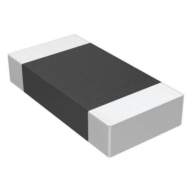
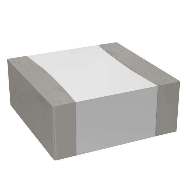
| 产品图片 |
|
| rohs | 符合RoHS无铅 / 符合限制有害物质指令(RoHS)规范要求 |
| 产品系列 | 铝电解电容器,铝有机聚合物电容器,AVX ML03512R5BAT2AMLO™ |
| 数据手册 | |
| 产品型号 | ML03512R5BAT2A |
| 产品 | Organic Polymer Aluminum - SMD Capacitors |
| 产品种类 | 铝有机聚合物电容器 |
| 产品类型 | Molded |
| 其它名称 | 478-6722-6 |
| 加载寿命 | 1000 h |
| 包装 | Digi-Reel® |
| 厚度(最大值) | 0.029"(0.74mm) |
| 商标 | AVX |
| 商标名 | MLO |
| 外壳代码-in | 0603 |
| 外壳宽度 | 0.838 mm |
| 外壳长度 | 1.6 mm |
| 外壳高度 | 0.63 mm |
| 大小/尺寸 | 0.063" 长 x 0.033" 宽(1.60mm x 0.84mm) |
| 安装类型 | 表面贴装,MLCC |
| 容差 | 0.1 pF |
| 封装 | Reel |
| 封装/外壳 | 0603(1608 公制) |
| 封装/箱体 | 0603 (1608 metric) |
| 工作温度 | -55°C ~ 125°C |
| 工厂包装数量 | 3000 |
| 应用 | RF,微波,高频 |
| 引线形式 | - |
| 引线间距 | - |
| 最大工作温度 | + 125 C |
| 最小工作温度 | - 55 C |
| 标准包装 | 1 |
| 温度系数 | C0G,NP0 |
| 特性 | 高 Q 值,低损耗 |
| 电压-额定 | 50V |
| 电压额定值DC | 50 V |
| 电容 | 2.5 pF |
| 端接类型 | SMD/SMT |
| 等级 | - |
| 系列 | ML |
| 高度 | 0.63 mm |
| 高度-安装(最大值) | - |


- 商务部:美国ITC正式对集成电路等产品启动337调查
- 曝三星4nm工艺存在良率问题 高通将骁龙8 Gen1或转产台积电
- 太阳诱电将投资9.5亿元在常州建新厂生产MLCC 预计2023年完工
- 英特尔发布欧洲新工厂建设计划 深化IDM 2.0 战略
- 台积电先进制程称霸业界 有大客户加持明年业绩稳了
- 达到5530亿美元!SIA预计今年全球半导体销售额将创下新高
- 英特尔拟将自动驾驶子公司Mobileye上市 估值或超500亿美元
- 三星加码芯片和SET,合并消费电子和移动部门,撤换高东真等 CEO
- 三星电子宣布重大人事变动 还合并消费电子和移动部门
- 海关总署:前11个月进口集成电路产品价值2.52万亿元 增长14.8%

PDF Datasheet 数据手册内容提取
Multi-Layer Organic Capacitors Based on its patented multilayer low loss organic (MLO®) technology. These new capacitors represent a paradigm shift from traditional ceramic and thin film passive SMD components. Multilayer Organic Capacitors (MLOC) are polymer based capacitors that use high conductivity copper interconnects in a multilayer fashion. The ability to fabricate these components on large area substrates and state of the art laser direct imaging allow for improved cost benefits and tolerance control. T he end result is a state of the art low ESR and high SRF low profile RF capacitor that can support frequencies well above one GHz. Additionally MLOCs are expansion matched to printed circuit boards to allow for improved reliability. FEATURES APPLICATIONS • Low ESR • RF Power Amplifiers • Hi-Q® • Low Noise Amplifiers • High Self Resonance • Filter Networks • Tight Tolerance • Instrumentation • Low Dielectric Absorption (0.0015%) HOW TO ORDER ML 03 7 1 1R8 P A T 2A Case Size Capacitance Failure Rate Packaging Code 03 = 0603 EIA Capacitance Code in pF. Code 2A = 7" Reel Unmarked First two digits = significant A = Not AVX Style VColotadgee figures or “R” for decimal Applicable place. 5 = 50V V = 250V Third digit = numberof zeros 7 = 500V or after “R” significant fig- ures. Capacitance Tolerance Code Temperature P = ± 0.02 pF Termination Style Coefficient Code Code A = ± .05 pF 1 = 0±30ppm B = ±.10 pF T = Ni, Sin R C = ±.25 pF T D = ±.5 pF F = ±1% G = ±2% J = ±5% B L LEAD-FREE COMPATIBLE COMPONENT W MECHANICAL DIMENSIONS: inches (millimeters) Case Length (L) Width (W) Thickness (T) Band Width (B) Castellation Radius (R) 0603 0.063 ± 0.004 0.033 ± 0.004 0.025 ± 0.004 0.015 ± 0.005 0.008 ± 0.002 (1.600 ± 0.102) (0.838 ± 0.102) (0.635 ± 0.102) (0.381 ± 0.127) (0.203 ± 0.051) TAPE & REEL: All tape and reel specifications are in compliance with EIA RS481 (equivalent to IEC 286 part 3). —8mm carrier —7" reel, 3,000 pcs per reel 012218 193
Multi-Layer Organic Capacitors ENVIRONMENTAL CHARACTERISTICS TEST CONDITIONS REQUIREMENT Life (Endurance) MIL-STD-202F 125°C, 2U , 1000 hours No visible damage (cid:2)C/C ≤2% for C≥5pF R Method 108A (cid:2)C/C ≤0.25pF for C<5pF Accelerated Damp Heat Steady 85°C, 85% RH, U , 1000 hours No visible damage (cid:2)C/C ≤2% for C≥5pF R State MIL-STD-202F Method 103B (cid:2)C/C ≤0.25pF for C<5pF Temperature Cycling –55°C to +125°C, 15 cycles –MLO® No visible damage (cid:2)C/C ≤2% for C≥5pF MIL-STD-202F Method 107E (cid:2)C/C ≤0.25pF for C<5pF MIL-STD-883D Method 1010.7 Resistance to Solder Heat 260°C ± 5°C for 10 secs. C remains within initial limits IEC-68-2-58 MECHANICAL SPECIFICATIONS TEST CONDITIONS REQUIREMENT Solderability IEC-68-2-58 Components completely immersed in Terminations to be well tinned, minimum 95% a solder bath at 235°C for 2 secs. coverage Leach Resistance IEC-68-2-58 Components completely immersed in Dissolution of termination faces ≤15% of area a solder bath at 260±5°C for 60 secs. Dissolution of termination edges ≤25% of length Adhesion MIL-STD-202F A force of 5N applied for 10 secs. No visible damage Method 211A Termination Bond Strength Tested as shown in diagram No visible damage (cid:2)C/C ≤2% for C≥5pF IEC-68-2-21 Amend. 2 (cid:2)C/C ≤0.25pF for C<5pF Robustness of Termination A force of 5N applied for 10 secs. No visible damage IEC-68-2-21 Amend. 2 Storage 12 months minimum with components Good solderability stored in “as received” packaging QUALITY & RELIABILITY • Solderability; • Dimensional, mechanical and temperature stability. MLO® capacitors utilize high density interconnect wiring technology on well established low loss organic materials. QUALITY ASSURANCE FINAL QUALITY INSPECTION The reliability of these multilayer organic capacitors has been extensively studied. Various methods and standards Finished parts are tested for standard electrical parameters have been used to ensure a high quality component and visual/mechanical characteristics. Each production lot including JEDEC, Mil Spec and IPC testing. AVX’s quality is 100% evaluated for: capacitance and proof voltage at assurance policy is based on well established international 2.5 UR. In addition, production is periodically evaluated for: industry standards. The reliability of the capacitors is • Average capacitance with histogram printout for determined by accelerated testing under the following capacitance distribution; conditions: • IR and Breakdown Voltage distribution; Life (Endurance) 125°C, 2U , 1000 hours R • Temperature Coefficient; Accelerated Damp 85°C, 85% RH, U , R Heat Steady State 1000 hours. TABLE I: CASE SIZE ML03 Cap. pF Cap. Tol. WVDC Cap. pF Cap. Tol. WVDC Cap. pF Cap. Tol. WVDC 0.1 P, A, B 50, 250, 500 1.3 P, A, B, C 50, 250, 500 3.0 P, A, B, C 50, 250 0.2 P, A, B 50, 250, 500 1.4 P, A, B, C 50, 250, 500 3.3 P, A, B, C 50, 250 0.3 P, A, B 50, 250, 500 1.5 P, A, B, C 50, 250, 500 3.6 P, A, B, C 50, 250 0.4 P, A, B 50, 250, 500 1.6 P, A, B, C 50, 250, 500 3.9 P, A, B, C 50, 250 0.5 P, A, B, C 50, 250, 500 1.7 P, A, B, C 50, 250, 500 Note: Capacitance measured at 1MHz. 0.6 P, A, B, C 50, 250, 500 1.8 P, A, B, C 50, 250, 500 0.7 P, A, B, C 50, 250, 500 1.9 P, A, B, C 50, 250, 500 0.8 P, A, B, C 50, 250, 500 2.0 P, A, B, C 50, 250, 500 0.9 P, A, B, C 50, 250, 500 2.2 P, A, B, C 50, 250, 500 1.0 P, A, B, C 50, 250, 500 2.4 P, A, B, C 50, 250, 500 1.1 P, A, B, C 50, 250, 500 2.5 P, A, B, C 50, 250, 500 1.2 P, A, B, C 50, 250, 500 2.7 P, A, B, C 50, 250 194 012218
Multi-Layer Organic Capacitors TTyyppicicaal lE ESSRR v sv.s F. rFerqeuqeunecnycy OPC 0603 MLO® 0603 10.00 1.00 0.4 pF 0.7 pF m 0.9 pF h O 1.4 pF 0.10 1.7 pF 2.2 pF 0.01 0.00 0.20 0.40 0.60 0.80 1.00 1.20 1.40 1.60 1.80 2.00 GHz Typical Q vs. Frequency MLO® 0603 10000 1000 2.5pF 100 2.0pF 1.5pF Q 1.0pF 10 0.5pF 1 0.1 -1 1 10 Frequency (GHz) 012218 195
Multi-Layer Organic Capacitors Typical Self Resonant Frequency vs. Capacitance Typical Self Resonant Frequency vs Capacitance MLOO®P0C60 03603 1000 z 10 H G 1 0.1 1 10 pF 196 012218