ICGOO在线商城 > 集成电路(IC) > PMIC - 栅极驱动器 > MIC4468ZWM
- 型号: MIC4468ZWM
- 制造商: Micrel
- 库位|库存: xxxx|xxxx
- 要求:
| 数量阶梯 | 香港交货 | 国内含税 |
| +xxxx | $xxxx | ¥xxxx |
查看当月历史价格
查看今年历史价格
MIC4468ZWM产品简介:
ICGOO电子元器件商城为您提供MIC4468ZWM由Micrel设计生产,在icgoo商城现货销售,并且可以通过原厂、代理商等渠道进行代购。 MIC4468ZWM价格参考。MicrelMIC4468ZWM封装/规格:PMIC - 栅极驱动器, Low-Side Gate Driver IC Non-Inverting 16-SOIC。您可以下载MIC4468ZWM参考资料、Datasheet数据手册功能说明书,资料中有MIC4468ZWM 详细功能的应用电路图电压和使用方法及教程。
| 参数 | 数值 |
| 产品目录 | 集成电路 (IC)半导体 |
| 描述 | IC DRIVER MOSF QUAD 1.2A 16SOIC门驱动器 Power Logic CMOS Quad Driver - Lead Free |
| 产品分类 | PMIC - MOSFET,电桥驱动器 - 外部开关集成电路 - IC |
| 品牌 | Micrel |
| 产品手册 | |
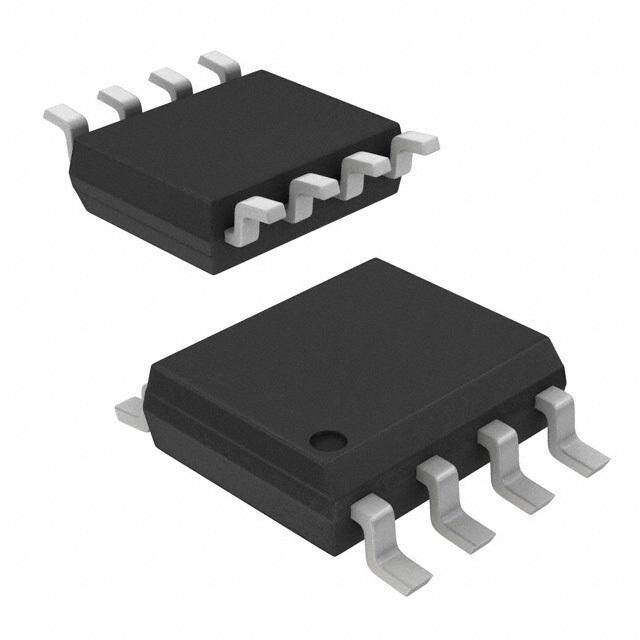
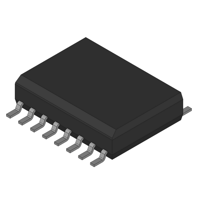
| 产品图片 |
|
| rohs | 符合RoHS无铅 / 符合限制有害物质指令(RoHS)规范要求 |
| 产品系列 | 电源管理 IC,门驱动器,Micrel MIC4468ZWM- |
| 数据手册 | |
| 产品型号 | MIC4468ZWM |
| 上升时间 | 17 ns |
| 下降时间 | 16 ns |
| 产品 | MOSFET Gate Drivers |
| 产品目录页面 | |
| 产品种类 | 门驱动器 |
| 供应商器件封装 | 16-SOIC |
| 其它名称 | 576-1213 |
| 包装 | 管件 |
| 商标 | Micrel |
| 安装类型 | 表面贴装 |
| 安装风格 | SMD/SMT |
| 封装 | Tube |
| 封装/外壳 | 16-SOIC(0.295",7.50mm 宽) |
| 封装/箱体 | SOIC-8 |
| 工作温度 | 0°C ~ 70°C |
| 工厂包装数量 | 47 |
| 延迟时间 | 35ns |
| 最大工作温度 | + 70 C |
| 最小工作温度 | 0 C |
| 标准包装 | 47 |
| 激励器数量 | 4 Driver |
| 电压-电源 | 4.5 V ~ 18 V |
| 电流-峰值 | 1.2A |
| 电源电压-最大 | 18 V |
| 电源电压-最小 | 4.5 V |
| 电源电流 | 0.2 mA |
| 类型 | Quad Low-Side MOSFET Driver |
| 系列 | MIC4468 |
| 输入类型 | 与 |
| 输出数 | 4 |
| 输出电流 | 1.2 A |
| 输出端数量 | 4 |
| 配置 | Quad |
| 配置数 | 4 |
| 高压侧电压-最大值(自举) | - |


- 商务部:美国ITC正式对集成电路等产品启动337调查
- 曝三星4nm工艺存在良率问题 高通将骁龙8 Gen1或转产台积电
- 太阳诱电将投资9.5亿元在常州建新厂生产MLCC 预计2023年完工
- 英特尔发布欧洲新工厂建设计划 深化IDM 2.0 战略
- 台积电先进制程称霸业界 有大客户加持明年业绩稳了
- 达到5530亿美元!SIA预计今年全球半导体销售额将创下新高
- 英特尔拟将自动驾驶子公司Mobileye上市 估值或超500亿美元
- 三星加码芯片和SET,合并消费电子和移动部门,撤换高东真等 CEO
- 三星电子宣布重大人事变动 还合并消费电子和移动部门
- 海关总署:前11个月进口集成电路产品价值2.52万亿元 增长14.8%


PDF Datasheet 数据手册内容提取
MIC4467/4468/4469 Micrel, Inc. MIC4467/4468/4469 Quad 1.2A-Peak Low-Side MOSFET Driver Bipolar/CMOS/DMOS General Description Features • Built using reliable, low power CMOS processes The MIC4467/8/9 family of 4-output CMOS buffer/drivers is an • Latchproof. Withstands 500mA Inductive Kickback expansion from the earlier single- and dual-output drivers, to • 3 Input Logic Choices which they are functionally closely related. Because package • Symmetrical Rise and Fall Times ............................25ns pin count permitted it, each driver has been equipped with a • Short, Equal Delay Times .......................................75ns 2-input logic gate for added flexibility. Placing four high-power • High Peak Output Current .......................................1.2A drivers in a single package also improves system reliability • Wide Operating Range ..................................4.5 to 18V and reduces total system cost. In some applications, one of • Low Equivalent Input Capacitance (typ) ..................6pF these drivers can replace not only two packages of single- • Inputs = Logic 1 for Any Input From 2.4V to V input drivers, but some of the associated logic as well. S • ESD Protected Although primarily intended for driving power MOSFETs, and similar highly capacitive loads, these drivers are equally Applications well suited to driving any other load (capacitive, resistive, or • General-Purpose CMOS Logic Buffer inductive), which requires a high-efficiency, low-impedance • Driving All 4 MOSFETs in an H-Bridge driver capable of high peak currents, rail-to-rail voltage swings, • Direct Small-Motor Driver and fast switching times. For example, heavily loaded clock • Relay or Peripheral Drivers lines, coaxial cables, and piezoelectric transducers can all be • Dual Differential Output Power Drivers driven easily with MIC446X series drivers. The only limitation • CCD Driver • Pin-Switching Network Driver Logic Diagrams MIC4467 MIC4468 MIC4469 V V V S S S 14 14 14 1 1 1 1A 13 1A 13 1A 13 2 1Y 2 1Y 2 1Y 1B 1B 1B 3 3 3 2A 12 2A 12 2A 12 4 2Y 4 2Y 4 2Y 2B 2B 2B 5 5 5 3A 11 3A 11 3A 11 6 3Y 6 3Y 6 3Y 3B 3B 3B 8 8 8 4A 10 4A 10 4A 10 9 4Y 9 4Y 9 4Y 4B 4B 4B 7 7 7 GND GND GND Micrel, Inc. • 2180 Fortune Drive • San Jose, CA 95131 • USA • tel + 1 (408) 944-0800 • fax + 1 (408) 474-1000 • http://www.micrel.com July 2005 1 MIC4467/4468/4469
MIC4467/4468/4469 Micrel, Inc. on loading is that total power dissipation in the IC must be to 5V of noise spiking (either polarity) occurs on the ground kept within the power dissipation limits of the package. line. They can accept up to half an amp of inductive kickback current (either polarity) into their outputs without damage or The MIC446X series drivers are built using a BCD process. logic upset. They will not latch under any conditions within their power and voltage ratings. They are not subject to damage when up Ordering Information Truth Table Inputs Output Part Number Temperature Part No. A B Y Range Package Standard Pb-Free MIC4467 L X H MIC44xxCN* MIC44xxZN* 0°C to +70°C 14-pin Plastic DIP (Each Driver) X L H MIC44xxCWM* MIC44xxZWM* 0°C to +70°C 16-pin Wide SOIC H H L MIC44xxBN* MIC44xxYN* –40°C to +85°C 14-pin Plastic DIP MIC4468 H H H (Each Driver) L X L MIC44xxBWM* MIC44xxYWM* –40°C to +85°C 16-pin Wide SOIC X L L * xx identifies input logic: MIC4469 L X L 67 — NAND 68 — AND 69 — AND with 1 inverting input (Each Driver) X H L **Pb-Free industrial grade PDIP available in MIC4468 & MIC4469 only. H L H Pin Configurations 14-Pin DIP (N) 16-Pin Wide SOIC (WM) 1A 1 14 VS 1A 1 16 VS 1B 2 13 1Y 1B 2 15 VS 2A 3 14 1Y 2A 3 12 2Y 2B 4 13 2Y 2B 4 11 3Y 3A 5 12 3Y 3A 5 10 4Y 3B 6 11 4Y 3B 6 9 4B GND 7 10 4B GND 7 8 4A GND 8 9 4A TOP VIEW TOP VIEW MIC4467/4468/4469 2 July 2005
MIC4467/4468/4469 Micrel, Inc. Block Diagrams V S MIC4467 5V Regulator INA Level Y OUT Shifter INB GND Functional Diagram for One Driver (Four Drivers per Package–Ground Unused Inputs) V S MIC4468 5V Regulator INA Level Shifter Y OUT INB GND Functional Diagram for One Driver (Four Drivers per Package–Ground Unused Inputs) V S MIC4469 5V Regulator INA Level Y OUT Shifter INB GND Functional Diagram for One Driver (Four Drivers per Package–Ground Unused Inputs) July 2005 3 MIC4467/4468/4469
MIC4467/4468/4469 Micrel, Inc. Absolute Maximum Ratings (Notes 1 and 2) Supply Voltage 22V Power Dissipation Input Voltage (GND – 5V) to (V + 0.3V) N Package (14-Pin Plastic DIP) 1.5W S Maximum Chip Temperature WM Package (16-Pin Wide SOIC) 1W Operating 150°C Storage –65° to +150°C Package Thermal Resistance Maximum Load Temperature N Package (14-Pin Plastic DIP) θ 80°C/W JA (10 sec, for soldering) 300°C WM Package (16-Pin Wide SOIC) θ 120°C/W JA Operating Ambient Temperature C Version 0° to +70°C B Version –40° to +85°C Electrical Characteristics: Measured at T = 25°C with 4.5V ≤ V ≤ 18V unless otherwise specified. (Note 3) A S Symbol Parameter Conditions Min Typ Max Units INPUT V Logic 1 Input Voltage 2.4 1.3 V IH V Logic 0 Input Voltage 1.2 0.8 V IL I Input Current 0 ≤ V ≤ V –1 1 µA IN IN S OUTPUT V High Output Voltage I = 10mA V -0.15 V OH LOAD S V Low Output Voltage I = 10mA 0.15 V OL LOAD R Output Resistance I = 10mA, V = 18V 5 15 Ω O OUT S I Peak Output Current 1.2 A PK I Latch-Up Protection >500 mA Withstand Reverse Current SWITCHING TIME t Rise Time Test Figure 1 14 25 ns R t Fall Time Test Figure 1 13 25 ns F t Delay Time Test Figure 1 30 75 ns D1 t Delay Time Test Figure 1 45 75 ns D2 POWER SUPPLY I Power Supply Current 0.2 4 mA S Supply Note 3. Specification for packaged product only. MIC4467/4468/4469 4 July 2005
MIC4467/4468/4469 Micrel, Inc. Electrical Characteristics: Measured over operating temperature range with 4.5V ≤ V ≤ 18V unless otherwise specified. S Symbol Parameter Conditions Min Typ Max Units INPUT V Logic 1 Input Voltage 2.4 1.4 V IH V Logic 0 Input Voltage 1.0 0.8 V IL I Input Current 0 ≤ V ≤ V –1 1 µA IN IN S OUTPUT V High Output Voltage I = 10 mA V -0.3 V OH LOAD S V Low Output Voltage I = 10 mA 0.3 V OL LOAD R Output Resistance I = 10 mA, V = 18V 7 30 Ω O OUT S I Peak Output Current 1.2 A PK I Latch-Up Protection 500 mA Withstand Reverse Current SWITCHING TIME t Rise Time Test Figure 1 17 50 ns R t Fall Time Test Figure 1 16 50 ns F t Delay Time Test Figure 1 35 100 ns D1 t Delay Time Test Figure 1 55 100 ns D2 POWER SUPPLY I Power Supply Current 0.4 8 mA S Supply NOTE 1: Functional operation above the absolute maximum stress ratings is not implied. NOTE 2: Static sensitive device. Store only in conductive containers. Handling personnel and equipment should be grounded to pre- vent static damage. July 2005 5 MIC4467/4468/4469
MIC4467/4468/4469 Micrel, Inc. Typical Characteristics Rise and FallTime vs. Rise and FallTime SupplyVoltage DelayTime vs. SupplyVoltage vs.Temperature 70 35 40 C = 1000pF C = 1000pF C = 1000pF 60 T AL = 25°C 30 T AL = 25°C VS L = 18V 50 25 30 TD2 TF me(ns) 4300 me(ns) 2105 TD1 me(ns) 20 TR Ti 20 TR Ti 10 Ti 10 TF 5 10 0 0 0 5 10 15 20 0 5 10 15 20 -75-50 -25 0 25 50 75100125150 SUPPLY VOLTAGE (V) SUPPLY VOLTAGE (V) TEMPERATURE (°C) Supply Current vs. Rise and FallTime vs. DelayTime vs.Temperature Capacitive Load Capacitive Load 35 80 1k 30 CVS L == 1180V00pF TD2 mA) 7600 TV S A == 2158°VC 400kHz TV S A == 2158°VC 25 T ( 100 TR s) 20 REN 50 ns) (n TD1 UR 40 e( TF e 15 C m m Y 30 Ti Ti L 10 10 PP 20 200 U kHz 5 S 10 20kHz 0 0 1 -75 -50-25 0 25 50 75100125 150 10 100 1000 10000 10 100 1000 10000 TEMPERATURE (°C) CAPACITIVE LOAD (pF) CAPACITIVE LOAD (pF) Supply Current vs. Frequency High Output vs. Current Low Output vs. Current 30 1.20 1.20 TA = 25°C V S = 18V TA = 25°C VC = 5V TA = 25°C VS = 5V C = 1000pF mA) L .96 V).96 T RRENT ( 20 10 V V | (V)OUT .72 10 V OLAGE (.72 10 V U – V LY C 10 | V S .48 PUT .48 P 15 V T 15 V P 5 V U U .24 O.24 S 0 .00 .00 1 10 100 1000 0 10 20 30 40 50 60 70 8090100 0 10 20 30 40 50 60 70 8090100 FREQUENCY (kHz) CURRENT SOURCED (mA) CURRENT SUNK (mA) MIC4467/4468/4469 6 July 2005
MIC4467/4468/4469 Micrel, Inc. Quiescent Power Supply Quiescent Power Supply Current vs. SupplyVoltage Current vs. SupplyVoltage 2.5 400 A)2.0 A)300 m µ T ( T (200 N N E1.5 E R R R R150 U U LY C1.0 NBOOT LHO IANDPUTS LOGIC "1" LY C100 NBOOT LHO IANDPUTS LOGIC "0" PP TA = 25 °C PP TA = 25 °C U0.5 U S S50 0 0 0 5 10 15 20 0 5 10 15 20 SUPPLY VOLTAGE (V) SUPPLY VOLTAGE (V) Test Figure 1 INVERTING INPUT VS +5V 90% VINPUT 1 µF FILM 0.1 µF CERAMIC 10% tD1 tD2 VOUTPUT tF tR IN1 VOUT IN1 470 pF 18V 90% 90% IN2 0V 10% 10% IN2 NON-INVERTING INPUT IN3 +5V 90% IN3 VINPUT IN4 10% IN4 18V 90% 90% VOUTPUT tD1 tR tD2 tF 0V 10% 10% Package Power Dissipation Quad Driver Drives H Bridge to Control Motor Speed and Direction 1500 14-PIN PDIP +5VTO +15V 1250 SLOPE = –12 mW/°C MIC4467 1000 W) CW m 750 CCW (D DC BRUSH P MOTOR 500 16-PIN WIDE SOIC PWM SPEED 250 SLOPE = –8 mW/°C 0 25 50 75 100 125 150 AMBIENT TEMPERATURE (°C) GND July 2005 7 MIC4467/4468/4469
MIC4467/4468/4469 Micrel, Inc. Package Information .770 (19.558) MAX PIN 1 .215 (5.461) .045 (1.143) .280 (7.112) (4.064) .015 (0.381) .015 (0.381) .008 (0.2032) .100 (2.540) .090 (2.296) .015 (.3810) .330 (8.362) .045 (1.143) 14-Pin Plastic DIP (N) PIN 1 INCHES (MM) 0.297 (7.544) 0.031 (0.787) 0.099 (2.515) 0.293 (7.442) TYP TYP 7° 0.022 (0.559) TYP 0.018 (0.457) R (0.381) 5° TYP 0.326 (8.280) 0.405 (10.287) 10°TYP MIN 0.090 (2.286) 0.032 (0.813)TYP PLANE 0.404 (10.262) 16-Pin Wide SOP (WM) MICREL INC. 2180 FORTUNE DRIVE SAN JOSE, CA 95131 USA TEL + 1 (408) 944-0800 FAX + 1 (408) 474-1000 WEB http://www.micrel.com This information furnished by Micrel in this data sheet is believed to be accurate and reliable. However no responsibility is assumed by Micrel for its use. Micrel reserves the right to change circuitry and specifications at any time without notification to the customer. Micrel Products are not designed or authorized for use as components in life support appliances, devices or systems where malfunction of a product can reasonably be expected to result in personal injury. Life support devices or systems are devices or systems that (a) are intended for surgical implant into the body or (b) support or sustain life, and whose failure to perform can be reasonably expected to result in a significant injury to the user. A Purchaser’s use or sale of Micrel Products for use in life support appliances, devices or systems is a Purchaser’s own risk and Purchaser agrees to fully indemnify Micrel for any damages resulting from such use or sale. © 1998 Micrel, Inc. MIC4467/4468/4469 8 July 2005
Mouser Electronics Authorized Distributor Click to View Pricing, Inventory, Delivery & Lifecycle Information: M icrel: MIC4469ZWM TR MIC4467CWM TR MIC4467ZWM TR M icrochip: MIC4469ZN MIC4469YN MIC4467ZWM MIC4468BWM MIC4467ZN MIC4467CWM MIC4467BWM MIC4468ZWM MIC4467YWM MIC4469ZWM MIC4468YWM MIC4468ZN MIC4468YN MIC4469CWM MIC4469YWM 5962-9459403MCA MIC4468CWM-TR MIC4469CWM-TR MIC4467BWM-TR MIC4467CWM-TR MIC4468BWM-TR MIC4469YWM-TR MIC4468YWM-TR MIC4469ZWM-TR MIC4467YWM-TR MIC4469BWM-TR MIC4468ZWM-TR MIC4467ZWM-TR

 Datasheet下载
.jpg)

