ICGOO在线商城 > 集成电路(IC) > PMIC - 配电开关,负载驱动器 > MIC2981/82YWM
/MIC2981/82YWM.jpg)
 Datasheet下载
- 型号: MIC2981/82YWM
- 制造商: Micrel
- 库位|库存: xxxx|xxxx
- 要求:
| 数量阶梯 | 香港交货 | 国内含税 |
| +xxxx | $xxxx | ¥xxxx |
查看当月历史价格
查看今年历史价格
MIC2981/82YWM产品简介:
ICGOO电子元器件商城为您提供MIC2981/82YWM由Micrel设计生产,在icgoo商城现货销售,并且可以通过原厂、代理商等渠道进行代购。 MIC2981/82YWM价格参考¥22.20-¥22.20。MicrelMIC2981/82YWM封装/规格:PMIC - 配电开关,负载驱动器, 。您可以下载MIC2981/82YWM参考资料、Datasheet数据手册功能说明书,资料中有MIC2981/82YWM 详细功能的应用电路图电压和使用方法及教程。
Microchip Technology的MIC2981/82YWM是一款PMIC(电源管理集成电路)中的配电开关和负载驱动器。它主要用于需要高效、可靠地控制电源分配和负载驱动的应用场景。以下是该型号的主要应用场景:

 1. 便携式电子设备
   MIC2981/82YWM广泛应用于便携式电子设备中,如智能手机、平板电脑、可穿戴设备等。这些设备通常需要在不同的工作模式下动态调整电源分配,以延长电池寿命并优化性能。MIC2981/82YWM可以精确控制各个模块的供电,确保在待机或低功耗模式下关闭不必要的电路,从而节省电能。

 2. 工业控制系统
   在工业自动化领域,MIC2981/82YWM可用于控制各种传感器、执行器和其他外围设备的电源。它能够根据系统需求快速切换电源状态,确保在不同工作条件下提供稳定的电源支持。此外,其内置的保护功能(如过流保护、短路保护)有助于提高系统的可靠性和安全性。

 3. 通信设备
   通信设备如路由器、交换机、基站等需要高精度的电源管理。MIC2981/82YWM可以为这些设备中的不同组件提供独立的电源控制,确保每个模块都能在最佳的工作电压下运行。这不仅提高了系统的整体效率,还减少了因电源波动导致的故障风险。

 4. 汽车电子
   汽车电子系统中,MIC2981/82YWM可用于控制车载娱乐系统、导航系统、车身控制模块等的电源分配。它能够在车辆启动、熄火或其他特殊情况下,智能地管理和分配电源,确保各个子系统的正常运行。同时,其低静态电流特性有助于减少对车载电池的消耗。

 5. 消费类电子产品
   对于消费类电子产品如智能家居设备、游戏机等,MIC2981/82YWM可以实现灵活的电源管理,支持多种工作模式下的电源切换。它还可以通过外部控制信号实现远程或自动化的电源管理,提升用户体验。

总的来说,MIC2981/82YWM凭借其高效、可靠的电源管理和负载驱动能力,适用于多种需要精确电源控制的场景,特别是在便携式设备、工业控制、通信设备、汽车电子和消费类电子产品等领域表现出色。
| 参数 | 数值 |
| 产品目录 | 集成电路 (IC)半导体 |
| 描述 | IC DRIVER ARRAY HV/HC 8CH 18SOIC闭锁 Hi-Voltage, Hi-Current Source Driver Array - Lead Free |
| 产品分类 | PMIC - MOSFET,电桥驱动器 - 外部开关集成电路 - IC |
| 品牌 | Micrel |
| 产品手册 | |
| 产品图片 |
|
| rohs | 符合RoHS无铅 / 符合限制有害物质指令(RoHS)规范要求 |
| 产品系列 | 逻辑集成电路,闭锁,Micrel MIC2981/82YWM- |
| 数据手册 | |
| 产品型号 | MIC2981/82YWM |
| 产品目录页面 | |
| 产品种类 | 闭锁 |
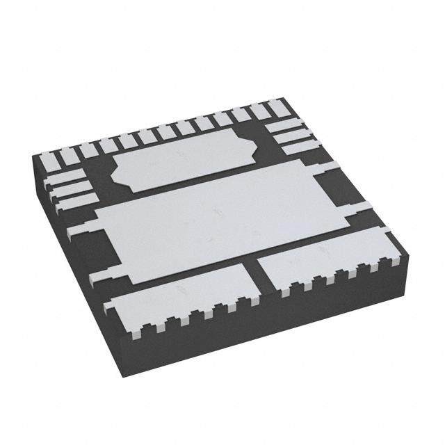
| 供应商器件封装 | 18-SOP(宽型) |
| 其它名称 | 576-1159 |
| 包装 | 管件 |
| 商标 | Micrel |
| 安装类型 | 表面贴装 |
| 安装风格 | SMD/SMT |
| 封装 | Tube |
| 封装/外壳 | 18-SOIC(0.295",7.50mm 宽) |
| 封装/箱体 | SOP-18 |
| 工作温度 | -40°C ~ 85°C |
| 工厂包装数量 | 41 |
| 延迟时间 | 1.0µs |
| 最大工作温度 | + 85 C |
| 最小工作温度 | - 40 C |
| 极性 | Non-Inverting |
| 标准包装 | 41 |
| 电压-电源 | 5 V ~ 50 V |
| 电流-峰值 | 500mA |
| 电源电压-最大 | 50 V |
| 电源电压-最小 | 5 V |
| 电源电流 | 10 mA |
| 电路数量 | 1 Circuit |
| 系列 | MIC2981/82 |
| 输入类型 | 非反相 |
| 输入线路数量 | 8 Line |
| 输出数 | 8 |
| 输出线路数量 | 8 Line |
| 逻辑类型 | CMOS |
| 逻辑系列 | TTL |
| 配置 | 高端 |
| 配置数 | 8 |
| 高压侧电压-最大值(自举) | - |


- 商务部:美国ITC正式对集成电路等产品启动337调查
- 曝三星4nm工艺存在良率问题 高通将骁龙8 Gen1或转产台积电
- 太阳诱电将投资9.5亿元在常州建新厂生产MLCC 预计2023年完工
- 英特尔发布欧洲新工厂建设计划 深化IDM 2.0 战略
- 台积电先进制程称霸业界 有大客户加持明年业绩稳了
- 达到5530亿美元!SIA预计今年全球半导体销售额将创下新高
- 英特尔拟将自动驾驶子公司Mobileye上市 估值或超500亿美元
- 三星加码芯片和SET,合并消费电子和移动部门,撤换高东真等 CEO
- 三星电子宣布重大人事变动 还合并消费电子和移动部门
- 海关总署:前11个月进口集成电路产品价值2.52万亿元 增长14.8%


PDF Datasheet 数据手册内容提取
MIC2981/2982 Micrel, Inc. MIC2981/2982 High-Voltage High-Current Source Driver Array General Features The MIC2981/82 is an 8-channel, high-voltage, high-current • Output voltage to 50V source driver array ideal for switching high-power loads from • Output current to 500mA logic-level TTL, CMOS, or PMOS control signals. • Transient-protected outputs • Integral clamp diodes These drivers can manage multiple loads of up to 50V and • TTL, CMOS, or PMOS compatible inputs 500mA, limited only by package power dissipation. Applications Micrel’s MIC2981/82 features inputs compatible with 5V TTL and 5V to 15V CMOS or PMOS logic outputs. Micrel’s • Relay and solenoid switching dual-marked device replaces either UDN2981 or UDN2982 • Stepping motor devices. • LED and incandescent displays The MIC2981/82 is available in the 18-pin plastic DIP and 18-lead wide SOP package. Both devices operate in the industrial temperature range. Ordering Information Part Number Reference Manufacturing* PbFree Temperature Range Package MIC2981BN** MIC2981/82BN MIC2981/82YN –40ºC to +85ºC 18-pin DIP MIC2982BN** MIC2981/82BN MIC2981/82YN –40ºC to +85ºC 18-pin DIP MIC2981BWM** MIC2981/82BWM MIC2981/82YWM –40ºC to +85ºC 18-pin wide SOP MIC2982BWM** MIC2981/82BWM MIC2981/82YWM –40ºC to +85ºC 18-pin wide SOP * Order entry P/N. **Orders for MIC2981BN or MIC2982BN will be filled with dual-marked MIC2981/82BN. **Orders for MIC2981YN or MIC2982YN will be filled with dual-marked MIC2981/82YN. **Orders for MIC2981BWM or MIC2982BWM will be filled with dual-marked MIC2981/82BWM. **Orders for MIC2981YWM or MIC2982YWM will be filled with dual-marked MIC2981/82YWM. Functional Diagrams IN1 OUT1 V S IN2 OUT2 20k IN3 OUT3 1.8k IN4–IN7 4 OUT4–OUT7 IN 800Ω IN8 OUT8 1.5k OUT GND V GND S Typical MIC2891/2982 Source Driver MIC2981 MIC2982 Micrel, Inc. • 2180 Fortune Drive • San Jose, CA 95131 • USA • tel + 1 (408) 944-0800 • fax + 1 (408) 474-1000 • http://www.micrel.com June 2005 1 MIC2981/2982
MIC2981/2982 Micrel, Inc. Pin Configuration IN1 1 18 OUT1 IN2 2 17 OUT2 IN3 3 16 OUT3 IN4 4 15 OUT4 IN5 5 14 OUT5 IN6 6 13 OUT6 IN7 7 12 OUT7 IN8 8 11 OUT8 V 9 10 GND S 18-Pin DIP (N) 18-Pin Wide SOP (WM) Pin Description Pin No. Pin No. Pin Name Pin Function 1–8 IN1–IN8 Input 1 through Input 8: Base drive to driver input transistor. 9 V Supply Input S 10 GND Ground 11–18 OUT8–OUT1 Output 8 through Output 1: Emitter of Darlington driver output. MIC2981/2982 2 June 2005
MIC2981/2982 Micrel, Inc. Absolute Maximum Ratings Operating Ratings Supply Voltage (V )......................................................50V Supply Voltage (V ) ............................................ 5V to 50V S S Output Voltage (V ) ....................................................50V Ambient Temperature (T ).........................–40°C to +85°C CE A Continuous Output Current (I )................................500mA Package Thermal Resistance C Input Voltage (VIN) PDIP θJA..............................................................56°C/W MIC2981/82...............................................................30V SOP θJA ..............................................................84°C/W Ground Current (I ) ....................................................3A GND Junction Temperature (T )......................................+150°C J Storage Temperature (T ) .......................–65°C to +150°C S Electrical Characteristics(Note 3) V = 50V, T = +25°C, unless noted. S A Symbol Parameter Condition Min Typ Max Units I Output Leakage Current V = 0.4V, T = +70°C, Note 1 200 µA CEX IN A V Output Sustaining Voltage I = 45mA 35 V CE(sus) OUT V Collector-Emitter Saturation Voltage V = 2.4V, I = 100mA 1.7 2.0 V CE(sat) IN OUT V = 2.4V, I = 225mA 1.8 2.1 V IN OUT V = 2.4V, I = 350mA 1.9 2.2 V IN OUT I Input Current MIC2981 V = 2.4V 140 200 µA IN(on) IN V = 3.85 310 450 µA IN MIC2982 V = 2.4V 140 200 µA IN V = 12V 1.25 1.93 mA IN I Output Source Current V = 2.4V, V = 2.2V 350 mA OUT IN CE I Supply Current V = 2.4, OUT1–8 = open, Note 1 10 mA S IN t Turn-On Delay 0.5E to 0.5E , R = 100Ω, V = 35V, 1.0 2.0 µs ON IN OUT L S t Turn-Off Delay 0.5E to 0.5E , R = 100Ω, V = 35V, 5.0 10 µs OFF IN OUT L S Note 2 I Clamp Diode Leakage Current V = 50V, V = 0.4V, Note 1 50 µA R R IN V Clamp Diode Forward Voltage I = 350mA 1.5 2.0 V F F General Note: Devices are ESD protected; however, handling precautions are recommended. Note 1: Applied to all 8 inputs simultaneously. Note 2: Load conditions affect turnoff delay. Note 3: Specification for packaged product only. June 2005 3 MIC2981/2982
MIC2981/2982 Micrel, Inc. Package Information 0.920(cid:0) MAX (23.370) PIN 1 0.030-0.110(cid:0) .250±0.005(cid:0) (0.762-2.794)RAD (6.350±0.127) 0.060±0.005(cid:0) (1.524±0.127) 0.020(cid:0) 0.290-0.320(cid:0) 0.130±0.005(cid:0) 0.040(cid:0)TYP (0.508) (7.336-8.128) (3.302±0.127) (1.016) 0°-10° 0.020(cid:0) MIN (0.508) 0.125(cid:0) MIN +0.025(cid:0) 0.018±0.003(cid:0) 0.100±0.010(cid:0) (3.175) 0.325 –0.015(cid:0) (0.457±0.076) (2.540±0.254) ( +0.635(cid:0)) 8.255 –0.381 18-Pin Plastic DIP (N) PIN 1 DIMENSIONS:(cid:0) INCHES (MM) 0.301 (7.645)(cid:0) 0.297 (7.544) 0.027 (0.686)(cid:0) 0.031 (0.787) 0.103 (2.616)(cid:0) 0.297 (7.544)(cid:0) 0.050 (1.270)(cid:0)0.016 (0.046)(cid:0)0.099 (2.515) 0.293 (7.442) TYP TYP 7°(cid:0) 0.022 (0.559)(cid:0) TYP 0.018 (0.457) 0.015(cid:0) R (0.381) 5°(cid:0) 0.459 (11.659)(cid:0) 0.015(cid:0) 0.330 (8.382)(cid:0) TYP 0.094 (2.388)(cid:0) 0.455 (11.557) (0.381)(cid:0) 0.326 (8.280) 10° TYP 0.090 (2.286) SEATING(cid:0)MIN 0.032 (0.813) TYP PLANE 0.408 (10.363)(cid:0) 0.404 (10.262) 18-Pin Wide SOP (WM) MICREL INC. 2180 FORTUNE DRIVE SAN JOSE, CA 95131 USA TEL + 1 (408) 944-0800 FAX + 1 (408) 474-1000 WEB http://www.micrel.com This information furnished by Micrel in this data sheet is believed to be accurate and reliable. However no responsibility is assumed by Micrel for its use. Micrel reserves the right to change circuitry and specifications at any time without notification to the customer. Micrel Products are not designed or authorized for use as components in life support appliances, devices or systems where malfunction of a product can reasonably be expected to result in personal injury. Life support devices or systems are devices or systems that (a) are intended for surgical implant into the body or (b) support or sustain life, and whose failure to perform can be reasonably expected to result in a significant injury to the user. A Purchaser’s use or sale of Micrel Products for use in life support appliances, devices or systems is a Purchaser’s own risk and Purchaser agrees to fully indemnify Micrel for any damages resulting from such use or sale. © 1999 Micrel Incorporated MIC2981/2982 4 June 2005
Mouser Electronics Authorized Distributor Click to View Pricing, Inventory, Delivery & Lifecycle Information: M icrochip: MIC2981/82YWM MIC2981/82YN MIC2981/82BWM MIC2981/82BWM-TR MIC2981/82YWM-TR