ICGOO在线商城 > 电路保护 > PTC 可复位保险丝 > MF-PSMF050X-2
 Datasheet下载
- 型号: MF-PSMF050X-2
- 制造商: Bourns
- 库位|库存: xxxx|xxxx
- 要求:
| 数量阶梯 | 香港交货 | 国内含税 |
| +xxxx | $xxxx | ¥xxxx |
查看当月历史价格
查看今年历史价格
MF-PSMF050X-2产品简介:
ICGOO电子元器件商城为您提供MF-PSMF050X-2由Bourns设计生产,在icgoo商城现货销售,并且可以通过原厂、代理商等渠道进行代购。 MF-PSMF050X-2价格参考¥2.92-¥4.02。BournsMF-PSMF050X-2封装/规格:PTC 可复位保险丝, 聚合物 PTC 自恢复保险丝 6V 500mA Ih 表面贴装 0805(2012 公制),凹陷。您可以下载MF-PSMF050X-2参考资料、Datasheet数据手册功能说明书,资料中有MF-PSMF050X-2 详细功能的应用电路图电压和使用方法及教程。
Bourns Inc.生产的MF-PSMF050X-2型号PTC可复位保险丝是一种过流保护器件,广泛应用于需要可靠电流过载保护的电子设备中。以下是其主要应用场景:

1. 消费类电子产品:如手机充电器、笔记本电脑适配器、平板电脑等便携式设备中,用于防止因短路或过流导致的损坏。

2. 家用电器:在小型家电(如电吹风、电动剃须刀、咖啡机等)中,提供过流和过温保护功能,确保设备安全运行。

3. 电池管理系统:用于锂电池组或电池保护电路中,防止电池因过流或短路而发生热失控,提升电池使用的安全性。

4. 通信设备:例如路由器、交换机、调制解调器等网络设备中,保护电路免受瞬时电流冲击或长期过载的影响。

5. 汽车电子:适用于车载娱乐系统、导航设备、车用传感器等场景,为电路提供稳定可靠的保护。

6. 工业控制设备:如PLC控制器、变频器、传感器模块等,防止因外部干扰或内部故障引起的过流问题。

MF-PSMF050X-2具有低电阻、高可靠性和自动恢复功能,能够在异常情况下迅速增加阻值以限制电流,并在故障排除后恢复正常工作状态,从而减少维修成本和时间。这种特性使其特别适合需要频繁插拔或可能遇到偶然过流情况的应用环境。
| 参数 | 数值 |
| 产品目录 | |
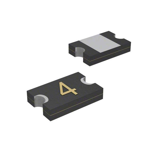
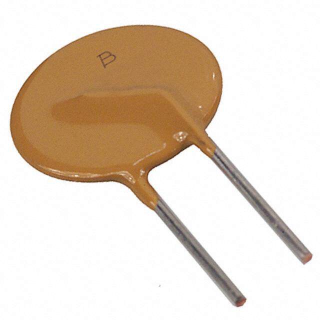
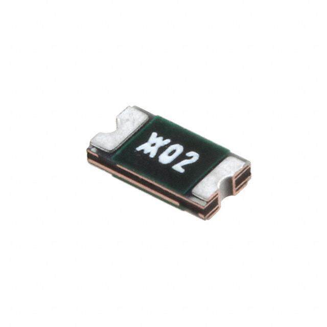
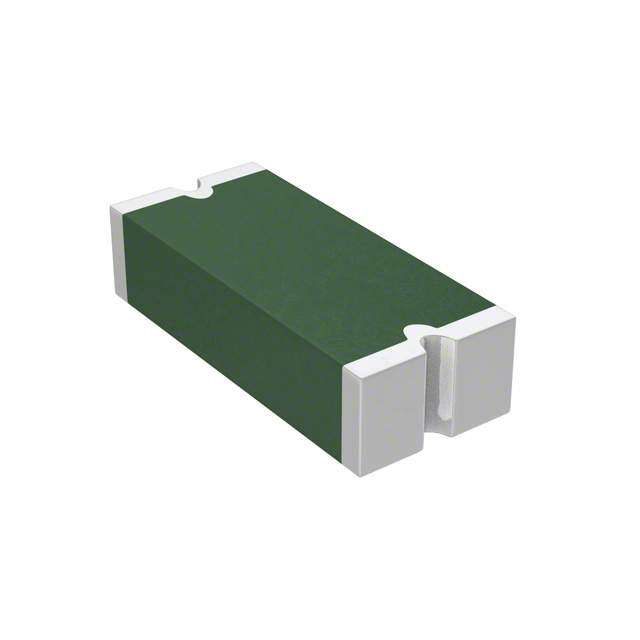
| 描述 | FUSE PTC RESETTABLE SMD 0805可复位保险丝—PPTC .50A 6V 0.15ohm Hold .5 Trip 1 |
| 产品分类 | |
| 品牌 | Bourns Inc. |
| 产品手册 | |
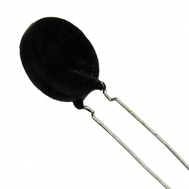
| 产品图片 |
|
| rohs | 符合RoHS无铅 / 符合限制有害物质指令(RoHS)规范要求 |
| 产品系列 | Bourns MF-PSMF050X-2MF-PSMF |
| mouser_ship_limit | 该产品可能需要其他文件才能进口到中国。 |
| 数据手册 | |
| 产品型号 | MF-PSMF050X-2 |
| PCN设计/规格 | |
| RoHS指令信息 | |
| R(最小/最大值) | 0.150 ~ 0.900 欧姆 |
| 产品培训模块 | http://www.digikey.cn/PTM/IndividualPTM.page?site=cn&lang=zhs&ptm=5252 |
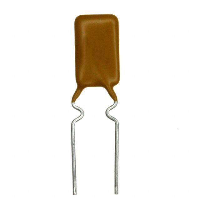
| 产品目录绘图 |
|
| 产品目录页面 | |
| 产品种类 | 可复位保险丝—PPTC |
| 保持电流 | 0.5 A |
| 其它名称 | MF-PSMF050X-2CT |
| 包装 | 剪切带 (CT) |
| 商标 | Bourns |
| 商标名 | Multifuse |
| 安装风格 | SMD/SMT |
| 封装 | Reel |
| 封装/外壳 | 0805(2012 公制),凹陷 |
| 封装/箱体 | 0805 (2012 metric) |
| 尺寸 | 2.3 mm L x 1.5 mm W x 0.85 mm H |
| 工作温度范围 | - 40 C to + 85 C |
| 工厂包装数量 | 3000 |
| 最大电压 | 6 VDC |
| 标准包装 | 1 |
| 电压-最大值 | 6V |
| 电流-保持(Ih)(最大值) | 500mA |
| 电流-最大值 | 40A |
| 电流-跳闸(It) | 1A |
| 电阻 | 900 mOhms |
| 端接类型 | SMD/SMT |
| 类型 | PTC Resettable Fuses |
| 系列 | MF-PSMF |
| 跳闸时间 | 0.1s |
| 跳闸电流 | 1 A |
| 额定电流—最大值 | 40 A |


X-2%20Side.jpg)


- 商务部:美国ITC正式对集成电路等产品启动337调查
- 曝三星4nm工艺存在良率问题 高通将骁龙8 Gen1或转产台积电
- 太阳诱电将投资9.5亿元在常州建新厂生产MLCC 预计2023年完工
- 英特尔发布欧洲新工厂建设计划 深化IDM 2.0 战略
- 台积电先进制程称霸业界 有大客户加持明年业绩稳了
- 达到5530亿美元!SIA预计今年全球半导体销售额将创下新高
- 英特尔拟将自动驾驶子公司Mobileye上市 估值或超500亿美元
- 三星加码芯片和SET,合并消费电子和移动部门,撤换高东真等 CEO
- 三星电子宣布重大人事变动 还合并消费电子和移动部门
- 海关总署:前11个月进口集成电路产品价值2.52万亿元 增长14.8%


PDF Datasheet 数据手册内容提取
NT *RoHS VCEOARVMSIAPILOLINAASB LE Features Applications NT MPLIA n Compact design to save board space - n USB port protection - USB 2.0, 3.0 & OTG RoHS CO n 0S8m0a5l l fsoiozetp rreinstults in very fast time to react nn HPCD MmIo 1th.4e rSboouarrcdes p- rPoltuegc taionnd Play * to fault events protection n Symmetrical design n Mobile phones - Battery and port protection n Low profile n PDAs / digital cameras REE n RoHS compliant* and halogen free** n Game console port protection D F n Agency recognition: LEA MF-PSMF Series - PTC Resettable Fuses Electrical Characteristics Model VV molatsx. IA mmapxLsVE.EA RDH SISF ORCNEOSE MAPRLIIEh ANoT*ldAmperesI trip ReOsihsmtasn ce AmpeMreTasox .T TriiSmpeec onds DiTsPWrsioipapwptateestrid o n Ro at 23 °C at 23 °C at 23 °C at 23 °C at 23 °C Hold Trip RMin. R1Max. Typ. MF-PSMF010X 15 40 0.10 0.30 1.0 7.5 0.5 1.5 0.5 MF-PSMF010/24X*** 24 80 0.10 0.30 1.0 7.5 0.5 1.5 0.5 MF-PSMF020X 9 40 0.20 0.50 0.65 3.5 8.00 0.02 0.5 MF-PSMF035X 6 40 0.35 0.75 0.250 1.200 8.00 0.10 0.5 MF-PSMF050X 6 40 0.50 1.00 0.150 0.900 8.00 0.10 0.5 MF-PSMF075X 6 40 0.75 1.50 0.090 0.350 8.00 0.20 0.6 MF-PSMF110X 6 40 1.10 2.20 0.060 0.210 8.00 0.30 0.6 ***TÜV approval pending. Environmental Characteristics Operating Temperature .........................................-40 °C to +85 °C Passive Aging .......................................................+85 °C, 1000 hours ...............................................±5 % typical resistance change Humidity Aging......................................................+85 °C, 85 % R.H. 1000 hours .............................±5 % typical resistance change Thermal Shock .....................................................+85 °C to -40 °C, 20 times ....................................±10 % typical resistance change Solvent Resistance ...............................................MIL-STD-202, Method 215 ...................................No change Vibration ...............................................................MIL-STD-883C, Method 2007.1, ...........................No change Condition A Test Procedures And Requirements For Model MF-PSMF Series Test Test Conditions Accept/Reject Criteria Visual/Mech. .........................................................Verify dimensions and materials ...........................Per MF physical description Resistance ............................................................In still air @ 23 °C .................................................Rmin ≤ R ≤ R1max Time to Trip ...........................................................At specified current, Vmax, 23 °C .........................T ≤ max. time to trip (seconds) Hold Current .........................................................30 min. at Ihold .....................................................No trip Trip Cycle Life .......................................................Vmax, Imax, 100 cycles ........................................No arcing or burning Trip Endurance .....................................................Vmax, 48 hours .....................................................No arcing or burning Solderability ..........................................................ANSI/J-STD-002 ...................................................95 % min. coverage UL File Number ....................................................E174545 http://www.ul.com/ Follow link to Certifications, then UL File No., enter E174545 TÜV Certificate Number .......................................R 50171531 http://www.tuvdotcom.com/ Follow link to “other certificates”, enter File No. 50171531 Thermal Derating Chart - Ihold (Amps) Ambient Operating Temperature Model -40 °C -20 °C 0 °C 23 °C 40 °C 50 °C 60 °C 70 °C 85 °C MF-PSMF010X 0.15 0.13 0.12 0.10 0.09 0.08 0.07 0.06 0.05 MF-PSMF010/24X 0.15 0.13 0.12 0.10 0.09 0.08 0.07 0.06 0.05 MF-PSMF020X 0.28 0.25 0.23 0.20 0.17 0.14 0.12 0.10 0.07 MF-PSMF035X 0.47 0.44 0.39 0.35 0.30 0.27 0.24 0.20 0.14 MF-PSMF050X 0.68 0.62 0.55 0.50 0.40 0.37 0.33 0.29 0.23 MF-PSMF075X 1.00 0.90 0.79 0.75 0.63 0.57 0.53 0.42 0.35 MF-PSMF110X 1.45 1.35 1.20 1.10 0.92 0.84 0.75 0.65 0.52 * RoHS Directive 2002/95/EC Jan. 27, 2003 including annex and RoHS Recast 2011/65/EU June 8, 2011. **Bourns considers a product to be “halogen free” if (a) the Bromine (Br ) content is 900 ppm or less; (b) the Chlorine ( Cl ) content is 900 ppm or less; and (c) the total Bromine (Br) and Chlorine ( Cl ) content is 1500 ppm or less. Specifications are subject to change without notice. Users should verify actual device performance in their specific applications. The products described herein and this document are subject to specific legal disclaimers as set forth on the last page of this document, and at www.bourns.com/docs/legal/disclaimer.pdf.
Additional Applications n Automotive electronic control modules MF-PSMF Series - PTC Resettable Fuses Product Dimensions A B C D Model Min. Max. Min. Max. Min. Max. Min. 2.00 2.30 1.20 1.50 0.48 0.85 0.20 MF-PSMF010X (0.079) (0.091) (0.047) (0.059) (0.019) (0.033) (0.008) 2.00 2.30 1.20 1.50 0.48 0.85 0.20 MF-PSMF010/24X (0.079) (0.091) (0.047) (0.059) (0.019) (0.033) (0.008) 2.00 2.30 1.20 1.50 0.48 0.85 0.20 MF-PSMF020X (0.079) (0.091) (0.047) (0.059) (0.019) (0.033) (0.008) 2.00 2.30 1.20 1.50 0.48 0.85 0.20 MF-PSMF035X (0.079) (0.091) (0.047) (0.059) (0.019) (0.033) (0.008) 2.00 2.30 1.20 1.50 0.48 0.85 0.20 MF-PSMF050X (0.079) (0.091) (0.047) (0.059) (0.019) (0.033) (0.008) 2.00 2.30 1.20 1.50 0.75 1.25 0.20 MF-PSMF075X (0.079) (0.091) (0.047) (0.059) (0.030) (0.049) (0.008) 2.00 2.30 1.20 1.50 0.75 1.25 0.20 MF-PSMF110X (0.079) (0.091) (0.047) (0.059) (0.030) (0.049) (0.008) Packaging: 3000 pcs. per reel. DIMENSIONS: MM (INCHES) Top View Bottom View Side View Recommended Pad Layout Terminal material: Nickel/gold plated. A C Termination pad solderability: Standard Au finish: 1.50 ± 0.10 4 B (.059 ± .004) Meets ANSI/J-STD-002 Category 2. Recommended Storage: 40 °C max./70 % RH max. D 1.00 ± 0.05 1.20 ± 0.10 (.039 ± .002) (.047 ± .004) Typical Time to Trip at 23 ˚C 10 The Time to Trip curves represent typical performance of MF-PSMF020X MF-PSMF035X a device in a simulated application environment. Actual MF-PSMF050X performance in specific customer applications may differ MF-PSMF075X from these values due to the influence of other variables. MF-PSMF110X 1 s) d n co MF-PSMF010X e S p ( 0.1 Tri o me t MF-PSMF010/24X Ti 0.01 0.001 Specifications are subject to change without notice. Users should verify actual device performance in their 0.0001 specific applications. 0.1 1 10 100 The products described herein and this document are subject to specific legal disclaimers as set forth on the last page of this Current (Amps) document, and at www.bourns.com/docs/legal/disclaimer.pdf.
MF-PSMF Series - PTC Resettable Fuses Solder Reflow Recommendations tp Notes: TP CRITICAL ZONE • MF-FSML models cannot be wave soldered or hand soldered. Please RAMP-UP TLTO TP contact Bourns for soldering recommendations. TL • All temperatures refer to topside of the package, measured on the tL package body surface. ature TSMAX. RAMP-DOWN • nIf orte mfloewe tt ethmep peurabtluisrheesd e sxpceeceidfi cthaetio rnesc.ommended profile, devices may er • Compatible with Pb and Pb-free solder reflow profiles. Temp TSMIN. PREtHsEAT • Esoxlcdeesrisn gso. lPdleera msea yre cfearu tsoe t hae s hMourltt icfuirsceu®it ,P eoslpymeceiar lPlyT dCu rSinogld hearinndg Recommendation guidelines. 25 • Designed for single solder reflow operations. t 25 *C TO PEAK 8 MINS. Time MM DIMENSIONS: (INCHES) Profile Feature Pb-Free Assembly Average Ramp-Up Rate (TSmax to Tp) 3 °C / second max. PREHEAT: Temperature Min. (TSmin) 150 °C Temperature Max. (TSmax) 200 °C TimDePesr c(otrcsiepmstisoinn to tsmax) Materials Temperature InTtiemrveal Iancscpeepctat bsloel d(ie.er .j oe6ixnh0ti b~toi1t sd8 ew0tee rtsmtieningce oo ifnf jsodoisnldt’esr sjouirnfat cise). Use the following criteria (ref. acceptability of printed 1.TApIMplyE s oMldAerI NpaTstAe ItNoED AB•OSVn E96: .5 / Ag 3.0 / Cu 0.5 Room temperature board assemblies, IPC-A-610): t e s t Tbeoamrdp (e8 r-a 1t0u rmeil (tThiIc)k ) cAlleloayn wsoaltdeer rs poalusbtele or no A) Acceptable (see Fig2ur1e7 1 )°C Time (tL) (see note 1) (1)The solde6r 0c~on1n5ec0t iosne wcoetntindgs angle (solder to •single sided epoxy glass component and solder to PCB termination) Peak / Classification Tem(Gp1e0r)a (tUuLr eap p(rTovPe)d) does not exceed2 9600 ° .°C •PC board approx. 4x4x.06 in. Time within 5 °C of Actual Peak Temperature (tp) (2)Solder bal2ls0 t~ha4t 0do s neoct ovinoldatse minimum 2.Place test units onto board 6 units/board electrical clearances and are attached 3.RRaammp pu-pDown Rate Convection oven (see note 2) 2.5 °C ± 0.5 °/sec. (soldere6d )° tCo a/ mseetcalo snudrf amcea.x. 4.TPrimeheea tw (TitSh)in 25 °C to Peak Temperature 150°Cto190°C 90±30sec. B) Unacceptable 8(s mee iFniguutrees 2 )max. 5.Time above liquidus (TL) 220°C 60-90sec. (1)Solder connection wetting angle exceeding 90 °. 6.Peak temperature (TP) 250°C+0°/-5° How to Order Typical Part M10a-2r0k sinecg. within (2)Incomplete reflow of solder paste. 5 °C of peak (3)Dewetting. 7.Rampdown MF - PSMF 010 /24 X - 2 RRooemptreemspeenrattsu rteota3l °cCo±n0te.5n°tC. /sLeacy.outI f munaaycc vepatrayb.le, determine cause and correct prior to (see note 2) PART IDEnNeTxIFt IrCuAnT.ION: MD8.euCsllteiigfaunnsianetgo® rwPartoedr uclceta n profile High pressure deionized 72 °F to 160 °F As required MMFF--PPSSMMFFN0011O00TX/2E 4=SX 1: = 1 Series water 65 PSI max. (22 °C to 71 °C) 4 MF-PSMF10.20XW =a t2er soluble solder pAasstei aon-lPy aabcovifie 1c0:0 K. PSMF = 0805 Surface Mount MF-PSMF20.35XR e=f 3er to ref. temperatuTree pl:r o+fi8le8. T6e-m2p e2ra5tu6r2e -a4t 117 Component MF-PSMF050X = 4 BIWEEKLY DATE CODE MF-PSMF075Xle =a d5/pad junction with E“Km” taypile: tahesrimaoccuosup@leb.ourns.com H Toelmd0 1pC0eu-rr1ar1et0nu tr(,e0 I .ho1o0fl d L- e1a.1d0/ PAamdp sJ)unction WILL APPEAR ON THE MF-PSMF31.10XU n= i6ts that are board mEouuntreod pfoer :e n vironmental (HDeigrihveedr uVsoinltga g6e-z oOnpe tCioonn vection Oven) PWAECEKKA 1G AINNGD L 2A =B EAL: tzeosntein, ga sm supsetc sifeieed a. pTehaisTk eitsel mt:o +p ee3nrsa6utu r8ree 8t hin a5 tt h2ael0l rte e3fslot9 w0 Blank = Standard Voltage WEEK 51 AND 52 = Z units will see “worst caEsem caonild:i teiounsro”.cus@bourns.com /24 = 24 V Multifuse® freeXpansion™ Design 4. Ramp down rate to be Tmheaes uAremd ferormic 2a45s :° C to 150 °C. Packaging Tel: +1-951 781-5500 Packaged per EIA 481-1 5. Process Description 8 Edomesa niol:t aapmplye troic oupesn@ bourns.com -2 = Tape and Reel frame trimmers. www.bourns.com MF-PSMF SERIES, REV. O 05/17 “freeXpansion Design” is a trademark of Bourns, Inc. Specifications are subject to change without notice. Users should verify actual device performance in their specific applications. The products described herein and this document are subject to specific legal disclaimers as set forth on the last page of this document, and at www.bourns.com/docs/legal/disclaimer.pdf.
MF-PSMF Series Tape and Reel Specifications MF-PSMF010X, MF-PSMF010/24X, MF-PSMF020X, MF-PSMF035X & MF-PSMF075X & MF-PSMF050X MF-PSMF110X Tape Dimensions per EIA 481-1 per EIA 481-1 8.0 ±0.30 8.0 ±0.30 W (0.315 ±0.012) (0.315 ±0.012) 4.0 ±0.10 4.0 ±0.10 P0 (0.157 ±0.004) (0.157 ±0.004) 4.0 ±0.10 4.0 ±0.10 P1 (0.157 ±0.004) (0.157 ±0.004) 2.0 ±0.05 2.0 ±0.05 P2 (0.079 ±0.002) (0.079 ±0.002) 1.65 ±0.10 1.65 ±0.10 A0 (0.065 ±0.004) (0.065 ±0.004) 2.4 ±0.10 2.4 ±0.10 B0 (0.094 ±0.004) (0.094 ±0.004) 4.35 4.35 B1max. (0.171) (0.171) 1.50 + 0.10/-0.0 1.50 + 0.10/-0.0 D0 (0.059 + 0.004/-0) (0.059 + 0.004/-0) 3.5 ±0.05 3.5 ±0.05 F (0.138 ±0.002) (0.138 ±0.002) 1.75 ±0.10 1.75 ±0.10 E1 (0.069 ±0.004) (0.069 ±0.004) 6.25 6.25 E2min. (0.246) (0.246) 0.6 0.6 T max. (0.024) (0.024) 0.10 0.10 T1max. (0.004) (0.004) 0.95 ±0.10 1.25 ±0.10 K0 (0.037 ±0.004) (0.049 ±0.004) 390 390 Leader min. (15.35) (15.35) 160 160 Trailer min. (6.30) (6.30) Reel Dimensions 185 185 A max. (7.28) (7.28) 50 50 N min. (1.97) (1.97) 8.4 + 1.5/ -0.0 8.4 + 1.5/ -0.0 W1 (0.331 + 0.059/-0) (0.331 + 0.059/-0) 14.4 14.4 W2 max. (0.567) (0.567) MM UNIT = (INCHES) P0 T D0 P2 E1 W2(MEASURED AT HUB) COVER TAPE F A N(HUB DIA.) E2W B1 B0 K0 P1 W1(AMT EHAUSBU)RED T1 A0 Specifications are subject to change without notice. Users should verify actual device performance in their specific applications. The products described herein and this document are subject to specific legal disclaimers as set forth on the last page of this document, and at www.bourns.com/docs/legal/disclaimer.pdf.
Legal Disclaimer Notice This legal disclaimer applies to purchasers and users of Bourns® products manufactured by or on behalf of Bourns, Inc. and its affiliates (collectively, “Bourns”). Unless otherwise expressly indicated in writing, Bourns® products and data sheets relating thereto are subject to change without notice. Users should check for and obtain the latest relevant information and verify that such information is current and complete before placing orders for Bourns® products. The characteristics and parameters of a Bourns® product set forth in its data sheet are based on laboratory conditions, and statements regarding the suitability of products for certain types of applications are based on Bourns’ knowledge of typical requirements in generic applications. The characteristics and parameters of a Bourns® product in a user application may vary from the data sheet characteristics and parameters due to (i) the combination of the Bourns® product with other components in the user’s application, or (ii) the environment of the user application itself. The characteristics and parameters of a Bourns® product also can and do vary in different applications and actual performance may vary over time. Users should always verify the actual performance of the Bourns® product in their specific devices and applications, and make their own independent judgments regarding the amount of additional test margin to design into their device or application to compensate for differences between laboratory and real world conditions. Unless Bourns has explicitly designated an individual Bourns® product as meeting the requirements of a particular industry standard (e.g., ISO/TS 16949) or a particular qualification (e.g., UL listed or recognized), Bourns is not responsible for any failure of an individual Bourns® product to meet the requirements of such industry standard or particular qualification. Users of Bourns® products are responsible for ensuring compliance with safety-related requirements and standards applicable to their devices or applications. Bourns® products are not recommended, authorized or intended for use in nuclear, lifesaving, life-critical or life-sustaining applications, nor in any other applications where failure or malfunction may result in personal injury, death, or severe property or environmental damage. Unless expressly and specifically approved in writing by two authorized Bourns representatives on a case-by-case basis, use of any Bourns® products in such unauthorized applications might not be safe and thus is at the user’s sole risk. Life-critical applications include devices identified by the U.S. Food and Drug Administration as Class III devices and generally equivalent classifications outside of the United States. Bourns expressly identifies those Bourns® standard products that are suitable for use in automotive applications on such products’ data sheets in the section entitled “Applications.” Unless expressly and specifically approved in writing by two authorized Bourns representatives on a case-by-case basis, use of any other Bourns® standard products in an automotive application might not be safe and thus is not recommended, authorized or intended and is at the user’s sole risk. If Bourns expressly identifies a sub-category of automotive application in the data sheet for its standard products (such as infotainment or lighting), such identification means that Bourns has reviewed its standard product and has determined that if such Bourns® standard product is considered for potential use in automotive applications, it should only be used in such sub-category of automotive applications. Any reference to Bourns® standard product in the data sheet as compliant with the AEC-Q standard or “automotive grade” does not by itself mean that Bourns has approved such product for use in an automotive application. Bourns® standard products are not tested to comply with United States Federal Aviation Administration standards generally or any other generally equivalent governmental organization standard applicable to products designed or manufactured for use in aircraft or space applications. Bourns expressly identifies Bourns® standard products that are suitable for use in aircraft or space applications on such products’ data sheets in the section entitled “Applications.” Unless expressly and specifically approved in writing by two authorized Bourns representatives on a case-by-case basis, use of any other Bourns® standard product in an aircraft or space application might not be safe and thus is not recommended, authorized or intended and is at the user’s sole risk. The use and level of testing applicable to Bourns® custom products shall be negotiated on a case-by-case basis by Bourns and the user for which such Bourns® custom products are specially designed. Absent a written agreement between Bourns and the user regarding the use and level of such testing, the above provisions applicable to Bourns® standard products shall also apply to such Bourns® custom products. Users shall not sell, transfer, export or re-export any Bourns® products or technology for use in activities which involve the design, development, production, use or stockpiling of nuclear, chemical or biological weapons or missiles, nor shall they use Bourns® products or technology in any facility which engages in activities relating to such devices. The foregoing restrictions apply to all uses and applications that violate national or international prohibitions, including embargos or international regulations. Further, Bourns® products and Bourns technology and technical data may not under any circumstance be exported or re-exported to countries subject to international sanctions or embargoes. Bourns® products may not, without prior authorization from Bourns and/or the U.S. Government, be resold, transferred, or re-exported to any party not eligible to receive U.S. commodities, software, and technical data. To the maximum extent permitted by applicable law, Bourns disclaims (i) any and all liability for special, punitive, consequential, incidental or indirect damages or lost revenues or lost profits, and (ii) any and all implied warranties, including implied warranties of fitness for particular purpose, non-infringement and merchantability. For your convenience, copies of this Legal Disclaimer Notice with German, Spanish, Japanese, Traditional Chinese and Simplified Chinese bilingual versions are available at: Web Page: http://www.bourns.com/legal/disclaimers-terms-and-policies PDF: http://www.bourns.com/docs/Legal/disclaimer.pdf C1753 05/17/18R