
 Datasheet下载
- 型号: MDM-15SH003B-A174-1E
- 制造商: ITT CANNON
- 库位|库存: xxxx|xxxx
- 要求:
| 数量阶梯 | 香港交货 | 国内含税 |
| +xxxx | $xxxx | ¥xxxx |
查看当月历史价格
查看今年历史价格
MDM-15SH003B-A174-1E产品简介:
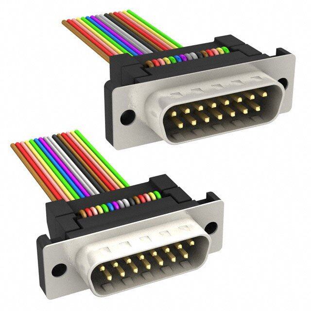
ICGOO电子元器件商城为您提供MDM-15SH003B-A174-1E由ITT CANNON设计生产,在icgoo商城现货销售,并且可以通过原厂、代理商等渠道进行代购。 MDM-15SH003B-A174-1E价格参考。ITT CANNONMDM-15SH003B-A174-1E封装/规格:D-Sub 电缆, D-Sub Cable Assembly to 。您可以下载MDM-15SH003B-A174-1E参考资料、Datasheet数据手册功能说明书,资料中有MDM-15SH003B-A174-1E 详细功能的应用电路图电压和使用方法及教程。


PDF Datasheet 数据手册内容提取
Cover headline Cover headline Microminiature Connectors Catalog
Amazing Things Happen When Great Things Connect More than a Century of Connections ITT Cannon is a leading global manufacturer of interconnect solutions serving international customers in the aerospace and defense, industrial, transportation and medical end markets. Whether delivering critical specs to aircraft pilots, streaming data through communications satellites, or enabling ultrasound equipment to give expectant parents a first look at their unborn child, ITT Cannon connects the world’s most important information with those who neeKde ity. SFinecaet 1u9r1e5s, Cannon products have been used in a history of “firsts.“ From the first “talking” movie to the first man on the moon, Cannon has set the standard for reliable, • Simple to install and maintain harsh environment interconnect solutions. Today we proudly continue our legacy of • Hand insertable contacts innovation with a goal to connect the world and inspire the successes of the next cen•tu Nryo— wbeedcgaeu sloec akms oarz ibnlgin dth sinegalss hreaqpupierend when great things connect. • From 2 way to 24-way layouts • Up to IP69K sealing The ITT Cannon Difference • Utilizes Trident Contacts • World-class design, engineering & manufacturing capabilities • Positive locking latch & polarization key • A commitment to quality at every touch point • Excellent cost/performance ratio • Global product reach with local customer service & support • Unrivaled customization experience • An innovative & trusted business partner About ITT ITT is a diversified leading manufacturer of highly engineered critical components and customized technology solutions for the energy, transportation and industrial markets. Building on its heritage of innovation, ITT partners with its customers to deliver enduring solutions to the key industries that underpin our modern way of life. ITT is headquartered in White Plains, N.Y., with employees in more than 35 countries and sales in approximately 125 countries. For more information, visit ITT.com www.ittcannon.com 2
Military & Defense Transportation Commercial Aerospace Medical ITT Cannon’s portfolio of high performance interconnects is one of the most Industrial extensive in the industry, offering a wide range of custom and off-the-shelf connectors and cable assemblies for applications in the Commercial Aerospace, Military & Defense, Transporation, Industrial and Medical end markets. For more details, visit ITTCannon.com. www.ittcannon.com 3
Microminiature Interconnect Solutions Ultra lightweight, space-saving connectors and cable assemblies for unmatched performance & reliability in the harshest environments ITT Cannon is your one-stop source for the design and manufacture of Microminiature solutions for the high performance connector Key Benefits market. • Ultra small, lightweight & high performance Offering one of the broadest selections of standard and custom form factor Microminiature products available, our versatile portfolio includes a • Available in 8 shell sizes that accommodate wide range of shell styles and configurations including rectangular, from 9 to 100 contacts, plus special power circular, quick disconnect, high speed signal, filter, hermetic, mixed and coaxial contact arrangements signal packages and strip-style. • Exceptional bandwidth performance Each one features our Cannon-engineered Micro Twist Pin Contact • Durability to withstand high shock and vibration System for maximum performance, as well as unique mechanical engagement and locking mechanisms to ensure reliability in the • Unique mechanical engagement & locking harshest environments. mechanisms • Custom & turnkey cable assemblies Ideally suited for markets and applications that require extremely small, lightweight and reliable interconnects, our Microminiature • RoHS compliant part numbers & plating options Connectors feature higher density contact configurations than traditional rectangular solutions—without sacrificing quality or performance. Key Features • Micro Twist Pin Contact System recessed into plug insulators • Positions: 9, 15, 21, 25, 31, 27, 51, 100 • Wire size: AWG 24 thru AWG 32 • Micro socket: Free standing used in receptacle side • Current rating: 3A • Durability: 500 mating cycles • Contacts: Copper alloy; gold plated • Low profile configurations available • Designed to MIL-DTL-83513 specifications • Operating temperatures: Micro MDM Standard: -55°C to +150°C High Temp Micro MDM: -55°C to +200°C Ultra-High Temp Micro MDM: -55°C to +230°C Dimensions shown in mm Specifications and dimensions subject to change www.ittcannon.com 4
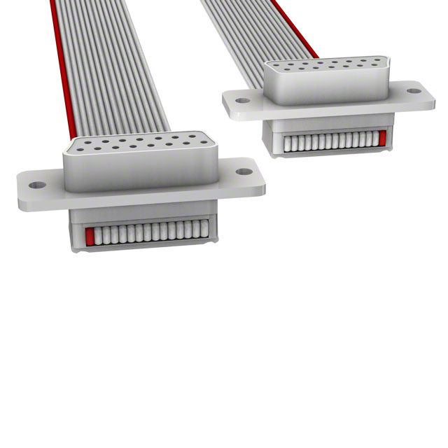
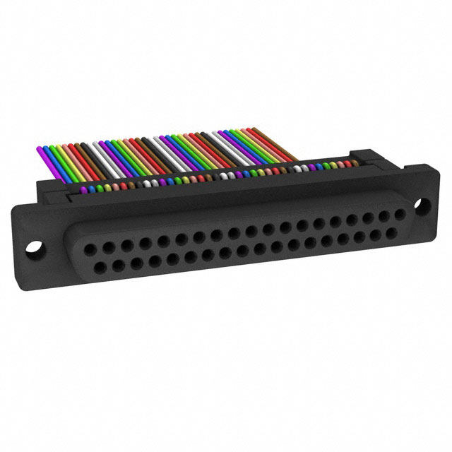
Markets & Applications From automated space vehicles roving the surface of Mars, to oil & gas exploration in remote locations the world over, ITT Cannon’s versatile, high performance Microminiature Connec- tors transmit data, power and signal when it matters most. Twist Pin Technology At the heart of our Microminiature Connector Series is the Twist Pin Contact System, which Cannon engineers first developed & licensed in the 1960s. Highly reliable Twist Pin Technology allows continuity in very dense areas and under severe shock and vibration, requiring low engagement and separation forces. It is superior technology that outperforms traditional machined or stamped electrical contract systems. To read more about this pioneering Cannon technology, please see page 7. Cable Assemblies Our extensive expertise in designing and manufacturing Microminiature Connectors translates into our ability to design and deliver both Turnkey and Custom Cable Assemblies. For more information, please see page 76. Microminiature Product Line • MDM Micro-D (MIL-DTL-83513) • MDM PCB (MIL-DTL-83513) • MDLM Micro-D Metal Shell, Low Profile • MDM F222 High Temp Micro • MDM F300 Ultra-High Temp Micro • MCM C/P Coaxial Power Micro • MDMH Hermetic Micro • TMDM Filter Micro • MD*Plastic Micro-D • MDB Coaxial Micro • MJS Micro Center Jacksrew • MIK Micro Circular • MIKM Micro Circular • MIKQ Micro Circular • MT* Strip-Style • ME Micro Edgeboard • Customs & Specials For more details, see our Product Selection Guide on pp 8-9. Dimensions shown in mm Specifications and dimensions subject to change www.ittcannon.com 5
Table of Contents Cannon Brand & Portfolio Overview ........................................................................................................2-3 Microminiature Interconnect Solutions Overview ....................................................................................4-5 Table of Contents ......................................................................................................................................6 Cannon Twist Pin Contact System ..............................................................................................................7 Product Selection Guide ........................................................................................................................8-9 Micro-D Metal Shell - .050” Contact Spacing (MDM) ..........................................................................10-18 Micro-D Coaxial/Power - .050” Contact Spacing (MDM-C/P) ................................................................19-20 Micro-D PCB - .050” Contact Spacing (MDM-PCB) ..............................................................................21-24 Micro-D Metal Shell Low Profile - 0.50” Contact Spacing (MDLM)........ ...............................................25-29 200ºC High-Temp Micro (MDM-F222) ................................................................................................30-31 230ºC Ultra-High Temp Micro (MDM-F300) .............................................................................................32 Accessories .............................................................................................................................................33 Micro-D Metal Shell - .050” Contact Spacing (MIL-DTL-83513) ...........................................................34-35 Hermetic (MDMH) ..............................................................................................................................36-37 Filter (TMDM) .....................................................................................................................................38-40 Micro-D Plastic Shell - .050” Contact Spacing (MD/MDB/MDB-PCB, MDV) ...........................................41-52 Micro Center Jackscrew (MJS) .............................................................................................................53-57 Microminiature Circular - .050” Contact Spacing (MIK, MIKM, MIKQ) .................................................58-64 Microstrips .050” Contact Spacing (MT) .............................................................................................65-68 Microminiature Strip - .100/.050” Contact Spacing (MT).....................................................................69-70 Micro Edgeboard - .050” Contact Spacing (MEB) ...............................................................................71-75 Cable Assemblies.....................................................................................................................................76 Flex Circuit Cable Assembly ......................................................................................................................77 Custom Back Shells .................................................................................................................................78 Appendix Standard Wire Termination “L” Code Chart ..........................................................................................79 Standard Wire Termination “H” Code Chart ........................................................................................80 Wire Color Code Chart ........................................................................................................................81 Micro-D Accessories Dust Caps ..........................................................................................................82 About ITT Cannon ...................................................................................................................................83 Product Safety Information ......................................................................................................................84 We Connect When It Matters Most ....................................................................................................85-86 www.ittcannon.com 6
Cannon Twist Pin Contact System At the heart of our Microminiature Connector Solutions is Cannon’s proven Twist Pin Contact System, which features superior electrical and mechanical technology that outperforms traditional machined or stamped electrical contract systems. Highly reliable twist pin technology allows continuity in very dense areas and under severe shock and vibration, requiring low engagement and separation forces. Termination can consist of uninsulated pigtails or insulated wire all pre-harnessed at our factory to customer specifications. Cannon engineers developed and introduced Twist Pin Contact Technology in the 1960s, and have used it in the Cannon MDM Series Microminiature Connectors for decades. ITT Cannon Cannon’s Twist Pin System consists of the Micro Socket and the Micro Pin or Twist Pin. Advantages of Cannon’s Twist Pin Contact System • Seven points of electrical contact (Micro 0.050 inch interconnect) • Contact and crimp sleeve materials carefully optimized for extremely reliable crimps; no design tradeoffs • Seamless crimp sleeves • Multiple 4-indent wire crimps standard & smaller bore micro socket contacts • Standard integral tail & thru bundle MicroPin contacts (high density packaging) • High mating cycles • High current handling capabilities • System qualification in numerous aerospace, defense, electronic & high temperature geophysical applications • Wide array of wire terminations How It Works: POS-A-Line Contact Alignment* The flexible Twist Pin is recessed into the insulator and the rigid socket is exposed, reversing the traditional positions of pin and socket. During mating, the socket is guided into the pin insulator by the lead-in chamfer. The pin is kept from flexing beyond the socket capture radius by the walls of the cavity. The hemispherical weld of controlled radius at the tip of the pin combines with the lead-in chamfers of the socket contact and the pin insulator to carn the pin into alignment. By controlling the welding process and the dimensions of the socket contact and the insulators, it is impossible for the recessed pin to escape the socket capture radius. Cannon MICROPIN NORMAL MATING CONDITIONS WIRE WELDED TIP WIRE CRIMP SEVERE MISALIGNMENT SLEEVE CRIMP Figure 1 AREA TWIST PIN CONTACTS WILL MATE EVEN UNDER SEVERE MISALIGNMENT *Figure 1 - The Twist Pin Contact System consists of several stranded cores making up the wire bundle. The strands are subsequently heat treated and a weld is performed on the tip of each contact. Crimp sleeves are then inserted over the contact and crimp areas Figure 2 are defined to produce a seamless crimp system. The Twist Pin Contact System is referred by ITT Cannon as a Pos-A-Line contact alignment system. Our reference to this system identifies that the flexible Twist Pin is recessed into the insulator and the rigid socket is exposed thus reversing the traditional positions of the pin and socket. During the mating sequence, the socket is guided into the Figure 2 - Illustrates the Twist Pin features, as well pin insulator by the lead-in chamfer. The pin is kept from flexing beyond the socket capture radius by the walls of the cavity. The as mating & severe misalignment conditions. hemispherical weld of controlled radius at the tip of the pin combines with the lead-in chamfer of the socket contact and the pin insulator to cam the pin in alignment. ITT Cannon has developed a very robust Six Sigma manufacturing process that controls the welding process as well as the dimensions of the socket contact and insulator material. The net result is a contact system that makes it impossible for the recessed pin to escape the socket capture radius. www.ittcannon.com 7
Cannon Microminiature Connectors | Product Selection Guide MDM High Temp Ultra-High MDMH MDM MDM PCB MDLM Coaxial/Power Micro Temp Micro MIL-DTL-83513 Hermetics Combo MDM F222 MDM F300 Applications MDM Connectors MDM-PCB Metal MDLM Connectors MDM C/P MDM F222 High MDM F300 High MIL-DTL-83513 Hermetically-sealed are highly reliable, Shell High Density offer are ideally Connectors have Temp Series is Temp Series is Connectors provide MDMH Connectors extremely small and Connectors are suited for harsh been tooled in tested to tested to high density, are designed for lightweight with designed for use environment several coaxial withstand 200°C withstand 230° con- lightweight, applications where higher density with flex circuitry, Aerospace & layouts and offer continuous tinuous operating field-proven a vacuum, inert contact flat cable and Defense, Industrial versatility by operating temperature for 500 twist pin contact gas or a constant configurations printed circuit and Transportation combining coaxial temperature for 500 hours and meets the design used in controlled pressure than traditional boards. applications that and signal lines hours and meets the harsh environment avionics gear, are required to rectangular require a thinner, in the same harsh environment requirements of the communications eliminate adverse connectors. lower profile design connector. requirements Oil and Gas explora- equipment and effects created package. of the Oil and tion industries. satellites, as by atmospheric Gas exploration well as medical changes. industries. applications. Available Plug and Socket Plug and Socket Plug and Socket Plug and Socket Plug and Socket Plug and Socket Plug and Socket Plug and Socket Layouts Current 3A max. 3A max. 3A max. 3A max. 3A max. 3A max. 3A max. 3A max. Rating Contact 24 milliohms 8 milliohms max. 8 milliohms max. 8 milliohms max. 8 milliohms max. 8 milliohms max. 8 milliohms max. 8 milliohms max. Resistance max. Contact gold plated gold plated gold plated gold plated gold plated gold plated gold plated gold plated Material copper alloy copper alloy copper alloy copper alloy copper alloy copper alloy copper alloy copper and steel Shell Metal Metal Metal Metal Metal Metal Metal Metal Shell Aluminum Aluminum Aluminum Aluminum Steel Stainless Steel Aluminum Steel Material 7C/P2, 24C/P4, Available 9, 15, 21, 25, 31, 9, 15, 21, 25, 31, 9, 15, 21, 25, 31, 9, 15, 21, 25, 31, 9, 15, 21, 25, 31 9, 15, 21, 25, 31, 9, 15, 21, 25, 31, 27C/P5 & 10C/ Layouts 37, 51 & 100 37, 51 & 100 37, 51 37 & 51 & 37 37, 51 & 100 37 & 51 P10 Configuration Polarized D Polarized D Polarized D Polarized D Polarized D Polarized D Polarized D Polarized D RoHS Available Available Available Available Not Available Not Available Available Available Plating Factory Yes* Yes Yes Yes Yes Yes Yes Yes* Terminated Space Available Available Available Available Yes No Available Yes Applications * Solderpot versions available for end user termination Dimensions shown in mm Specifications and dimensions subject to change www.ittcannon.com 8
TMDM MD** MJS MIK MIKM MIKQ MT* MEB Filter Applications MDM Filter MD** MJS Jackscrew MIK Micro Circular MIKM Micro MIKQ Micro Circular MT Microstrips pro- Micro Edgeboard Connectors are Microminiature Series provides a Series are rugged Circular Series are Series are rugged vide an extremely (MEB) Series pro- designed for use in Connectors are used reliable interconnect yet lighweight and rugged yet ligh- yet lighweight and dense and reliable vides a combination commercial avionics in applications for board-to-board, meet or exceed the weight and meet or meet or exceed the interconnection of high density and equipment, requiring highly board-to-cable and applicable exceed the applicable solution in a and reliability for with increasing reliable, extremely cable-to-cable requirements of applicable requirements of minimum profile applications in emphasis on small, lightweight applications. MIL-DTL-83513. requirements of MIL-DTL-83513. package, offering airborne and space EMI, RFI and plastic connectors. Applications include MIL-DTL-83513. Application include exceptional board- systems, computers EMP shielding. biomedical, Application include biomedical, to-wire application and peripherals, instrumentation biomedical, instrumentation flexibility. and industrial/ and miniature instrumentation and miniature commercial control black boxes. and miniature black boxes. systems. black boxes. Available Plug and Socket Plug and Socket Plug and Socket Plug and Socket Plug and Socket Plug and Socket Plug and Socket Plug and Socket Layouts Current 3A max. 3A max. 3A max. 3A max. 3A max. 3A max. 3A max. 3A max. Rating Contact 15 milliohms 8 milliohms max. 8 milliohms max. 8 milliohms max. 8 milliohms max. 8 milliohms max. 8 milliohms max. 8 milliohms max. Resistance max. Contact gold plated gold plated gold plated gold plated gold plated gold plated gold plated gold plated Material copper alloy copper alloy copper alloy copper alloy copper alloy copper alloy copper alloy copper alloy Shell Metal Plastic Plastic Plastic Metal Metal Plastic Plastic Shell Thermoplastic Thermoplastic Aluminum Thermoplastic Steel Steel Thermoplastic Thermoset Material & Thermoset & Thermoset 10, 26, 51 & 66 Rect/ unshrouded Available 9, 15, 21, 25, 31, 9, 15, 21, 25, 31, MTV - 1 thru 120 64, 128, 92 & 16, 28 & 35 7 & 55 7, 55 & 85 7, 19 & 37 Layouts 37 & 51 37 & 51 MTB - 1 thru 80 184 - Rect/shrouded 26, 38, 42 & 76 - Polarized D Rectangular & Configuration Polarized D Polarized D Circular Circular Circular Polarized D RoHS No Available Available Available Available Available Available Available Plating Factory Yes Yes* Yes* Yes Yes Yes Yes Yes Terminated Space Yes Available Available Yes Yes Yes Yes Yes Applications Dimensions shown in mm Specifications and dimensions subject to change www.ittcannon.com 9
Micro-D Metal Shell - .050” Contact Spacing MDM Cannon MDM Series Microminiature Connectors are used in applications requiring highly reliable, extremely small and lightweight solutions with higher density contact configurations. They are available in eight shell sizes that accommodate from 9 to 100 contacts, as well as special arrangements with power and coaxial contacts. Cannon MDM Series Microminiature Connectors employ size 24 Micro-Pin / Micro-Socket Contacts on .050 (1.27) centers in a contact density identical to the standard Micro-D connector series, but with Aluminum shells to increase strength, prevent chipping, cracking or breaking and provide electromagnetic (EMI and RFI shielding. They also feature a silicone elastomer compression interfacial seal to provide a moisture and humidity seal between each contact and between the contacts and shell. Specifications STANDARD MATERIALS AND FINISHES MECHANICAL FEATURES Shell - 6061-T6 Aluminum alloy per QQ-A-200/8, yellow chro- Coupling - Friction/jackscrews mate/cadmium, Type II, Class 3 over electroless nickel per SAE AMS-C-26074, Class 4. Polarization - Keystone-shaped shells Insulator - Liquid Crystal Polymer per MIL-M-24519, Contact Spacing - .050 (1.27) Type GLCP-30F (9-100) - Glass filled diallyl phthalate per Centers MIL-M-14, Type SDGF (7*2 and 24*4) Shell Styles - Plug and receptacle - Polyphenylene sulfide per MIL-M-24519, Type GST-40F (16*5) No. of Contacts - 9 thru 100 signal; - Polyester per MIL-M-24519, Type GPT-30F (10*10) 5 signal/2 coaxial; Contacts - Copper alloy, gold plate 5 signal/2 power; 11 signal/5 coaxial; Mounting Hardware - 300 Series stainless steel, passivate 11 signal/5 power; 0 signal/10 coaxial; Kit, Jackpost (3) items - 300 Series stainless steel, passivate 0 signal/10 power; 20 signal/4 coaxial; Washer - 400 Series stainless stell, passivate 20 signal/4 power Coaxial Cable - RG - 178/U Standard Epoxy - Hysol EE4215/HD3561, color black - Hysol EE4198/HD3561, color green Wire Size - #24 thru #32 AWG - Hysol MG40FS molding compound Contact Termination - Multiple indent crimp Performance Data Test Method Criteria of Acceptance Dielectric Withstanding Method 3001: No breakdown Voltage 600 VAC at sea level No breakdown 150 VAC at 70,00’ altitude Insulation Resistance Method 3003 5,000 megohms minimum Thermal Shock Method 1003. Condition A: - 55°C to +125°C No physical damage Physical Shock Method 2004, Condition E: 50 G’s, 3 axes, 6 millisecond No physical damage duration sawtooth pulse No loss of continuity > 1 μsec Vibration Method 2005, Condition IV: 20 G’s, 10-20,000 Hz. 12 hrs No physical damage No loss of continuity > 1 μsec Durability 500 cycles of mating and unmating, 500 CPH max. No mechanical or electrical defects Moisture Resistance Method 1002, Type II, omit steps 7a & 7b Insulation resistance > 100 megohms Salt Spray Method 1001, Condition B: 48 hours Shall be capable of mating and unmating, and meet contact resistance requirements Contact Resistance Method 1001, Condition B: At 3 amps 8 milliohms maximum (MIL-STD-202) At 1 milliamp 10 milliohms maximum Contact Retention Per MIL-DTL-83513 5 lb. minimum axial load Dimensions shown in mm Specifications and dimensions subject to change www.ittcannon.com 10
Micro-D Metal Shell - .050” Contact Spacing MDM How to Order (For MIL-DTL-83513 ordering information, see pp. 29-30) R MDM - 51 P H 001 P - XXX RoHS Compliance Series Contact Arrangements Contact Type Termination Type Termination Code Hardware Shell Finish Mod Codes Series Hardware MDM: (Size 9-100) Liquid Crystal Polymer (LCP) M - Military specification hardware, see page 16 MDM: (Combo Layout) Diallyl Phthalate (DAP) for military hardware codes. P - Jackpost Contact Arrangements K - Jackscrew-standard profile 9-15-21-25-31-37-51-100 (standard) L - Jackscrew-low profile 16C5, 10C10, 7C2, 24C4 (coaxial) or combination of F - Float mount 16P5, 10P10, 7P2, 24P4 (power) coax and power B - No hardware standard.091 (2.31) dia. hole for Contact Type sizes 9-51; .120 (3.05) dia. hole for size 100. P - Pin A - .125 (3.18) dia. mounting holes for sizes 9-51; S - Socket .166 (4.22) dia. hole for size 100. B1 - .1475 (3.75) dia. hole for size 100 (Per MIL-DTL-83513) Termination Type H - Harness-insulated wire. Shell Finish Modification Codes No Number - (Standard cadmium/yellow chromate over nickel L - Solid-uninsulated wire. A174 - Electroless nickel S - Solder pot to accept #26 AWG MAX. A172 - Gold over nickel harness wire. (Not available with power A141 - Irridite/alodine contact arrangements.) A30 - Black anodize Termination code* (H) 001 - 18”,7/34 strand,#26 AWG, MIL-W-16878/4, Type E Teflon, yellow. Modification Codes F222 - High Temp (200°C) (H) 003 - 18”, 7/34 strand, #26 AWG, MIL-W-16878/4, F234 - 24 AWG Wire Type E Teflon, color coded to MIL-STD-681 System I. A295 - Non-Magnetic (L) 1 - 1/2” uninsulated solid #25 AWG gold plated copper. K135 - F222 and A295 (L) 2 - 1” uninsulated solid #25 AWG gold plated copper. A214 - Hot tin dip K139 - F222 High (200°C) and F234 (24 AWG Wire) For additional termination codes, please see pages 79-81. Dimensions shown in mm Specifications and dimensions subject to change www.ittcannon.com 11
Micro-D Metal Shell - .050” Contact Spacing MDM Contact Arrangements Face View of Pin insert - Use Reverse Order for Socket Side .025 (0.64) TYP. .050 (1.27) .043 TYP. (1.09) 1 2 3 4 5 1 2 3 4 5 6 7 8 1 2 3 4 5 6 7 8 9 10 11 6 7 8 9 9 10 11 12 13 14 15 12 13 14 15 16 17 18 19 20 21 9 Contacts 15 Contacts 21 Contacts 1 2 3 4 5 6 7 8 9 10 11 12 13 1 2 3 4 5 6 7 8 9 10 11 12 13 14 15 16 1 2 3 4 5 6 7 8 9 10 11 12 13 14 15 16 17 18 19 14 15 16 17 18 19 20 21 22 23 24 25 17 18 19 20 21 22 23 24 25 26 27 28 29 30 31 20 21 22 23 24 25 26 27 28 29 30 31 32 33 34 35 36 37 25 Contacts 31 Contacts 37 Contacts 1 2 3 4 5 6 7 8 9 10 11 12 13 14 15 16 17 18 19 20 21 22 23 24 25 26 27 28 29 30 31 32 33 34 35 36 37 38 39 40 41 42 43 44 45 46 47 48 49 50 51 1 2 3 4 5 6 7 8 9 10 11 12 13 14 15 16 17 18 19 20 21 22 23 24 25 26 27 28 29 30 31 32 33 34 35 52 53 54 55 56 57 58 59 60 61 62 63 64 65 66 67 68 69 70 71 72 73 74 75 36 37 38 39 40 41 42 43 44 45 46 47 48 49 50 51 76 77 78 79 80 81 82 83 84 85 86 87 88 89 90 91 92 93 94 95 96 97 98 99 100 51 Contacts 100 Contacts Contact identication numbers are for reference only and do not appear on insulation or connector body. .320 .714 (18.14) .103 Coaxial (8.13) .460 (11.68) A1 A2 81569213 07141 A3 A4 A5 A1 1245 3 A2 A1 A2 1142891513641017111586121913270 A3 A4 .007 Size 51 Shell Size 25 Shell Size 51 Shell (0.18) 11 Micro contact 5 Micro contact 20 Micro contacts 5 Coax or 5 Power 2 Coax or 2 Power 4 Coax or 4 Power 16P5 7P2 (Not MS) 16C5 7C2 25P4 25C4 A1 A2 A3 A4 A5 A6 A7 A8 A9 A10 Size 100 Shell 0 Micro contact 10 Coax or 10 Power 10P10 10C10 Dimensions shown in mm Specifications and dimensions subject to change www.ittcannon.com 12
Micro-D Metal Shell - .050” Contact Spacing MDM (Conforms to MIL-DTL-83513) Plug .284 (7.21) .18M6 A(4X..72) (.20.9336) TWO MTG. HOLES MAX. B REF. .110 (2.79) .091 ±.003(2.31 ±0.08) MAX. F .416 (10.57) G D E MAX. .200 (5.08) C MAX. A Solder Pot Receptacle .296 (7.52) MAX. T.0W91O ± M.0T0G3(.2 H.3O1L ±E0S.08) B (.20.9336) .110 (2.79) F REF. MAX. .429 (10.09) MAX. G D E .20M0 A(5X..08) A C .19M8 A(5X..03) Solder Pot Receptacle (MDM-100 only) T.1W20O ± M.0T0G3(.3 H.0O5L ±E0S.08) .394M (A1.X402..09M1 ()A1X0.. 90) .19M8 A(5X..03) B .09R3 E(2F..36) G D E .296 (7.52) Pigtail termination F MAX. C A Part Number A B C D E F G Average Weights** By Shell Size Max. Max. Max. Max. Max. +_.005 (0.13) Max. oz. (gm.) ±5% MDM-9P* .785 (19.94) .334 (8.48) .400 (10.16) .270 (6.86) .308 (7.82) .565 (14.35) .185 (4.70) .063 (1.79) MDM-9S* .785 (19.94) .402 (10.21) .400 (10.16) .270 (6.86) .308 (7.82) .565 (14.35) .253 (6.43) .063 (1.79) MDM-15P* .935 (23.75) .484 (12.29) .550 (13.97) .270 (6.86) .308 (7.82) .715 (18.16) .185 (4.70) .084 (2.39) MDM-15S* .935 (23.75) .552 (13.97) .550 (13.97) .270 (6.86) .308 (7.82) .715 (18.16) .253 (6.43) .083 (2.37) MDM-21P* 1.085 (27.56) .634 (16.10) .700 (17.78) .270 (6.86) .308 (7.82) .865 (21.97) .185 (4.70) .105 (2.99) MDM-21P* 1.085 (27.56) .702 (17.83) .700 (17.78) .270 (6.86) .308 (7.82) .865 (21.97) .253 (6.43) .104 (2.97) MDM-25P* 1.185 (30.10) .734 (18.64) .800 (20.32) .270 (6.86) .308 (7.82) .965 (24.51) .185 (4.70) .119 (3.39) MDM-25S* 1.185 (30.10) .802 (20.37) .800 (20.32) .270 (6.86) .308 (7.82) .965 (24.51) .253 (6.43) .118 (3.36) MDM-31P* 1.335 (33.91) .884 (22.45) .950 (24.13) .270 (6.86) .308 (7.82) 1.115 (28.32) .185 (4.70) .140 (3.99) MDM-31S* 1.335 (33.91) .952 (24.18) .950 (24.13) .270 (6.86) .308 (7.82) 1.115 (28.32) .245 (6.43) .139 (3.96) MDM-37P* 1.485 (37.72) 1.034 (26.26) 1.100 (27.94) .270 (6.86) .308 (7.82) 1.265 (32.13) .185 (4.70) .161 (4.59) MDM-37S* 1.485 (37.72) 1.102 (27.99) 1.100 (27.94) .270 (6.86) .308 (7.82) 1.265 (32.13) .253 (6.43) .160 (4.56) MDM-51P* 1.435 (36.45) .984 (24.99) 1.050 (26.67) .310 (7.87) .351 (8.92) 1.215 (30.86) .228 (5.79) .193 (5.50) MDM-51S* 1.435 (36.45) 1.052 (26.72) 1.050 (26.67) .310 (7.87) .351 (8.92) 1.215 (30.86) .296 (7.52) .188 (5.35) MDM-100P* 2.170 (55.12) 1.384 (35.15) 1.442 (36.63) .360 (9.14) .394 (10.01) 1.800 (45.72) .271 (6.88) .500 (14.3) MDM-100S* 2.170 (55.12) 1.508 (38.10) 1.442 (36.63) .360 (9.14) .394 (10.01) 1.800 (45.72) .394 (10.01) 1.040 (29.5) *Add lead type and length; see How To Order. ***Weight given is 1/2” uninsulated, solid, #25 AWG gold plated copper pigtails. Panel Mounting Dimensions (Sizes 9 - 100) .200 ±.005 .300 ±.005 (5.08 ±0.13) (7.62 ±0.13) .395 ±.005 (10.03 ±0.13) Plug and Receptacle Plug and Receptacle Plug Front Mounted Rear Mounted Front Mounted Receptacle Rear Mounted Dimensions shown in mm Specifications and dimensions subject to change www.ittcannon.com 13
Micro-D Metal Shell - .050” Contact Spacing MDM Connector Saver Save wear and tear on your equipment and system connectors with Cannon’s MDM Connector Saver. Eliminate multiple mating and de-mating during testing and final checkout by simply mating the “Connector Saver” to your unit and using the opposite side for your testing interface. This result is less wear, less tear and less chance of damage. Our MDM Connector Saver is available in all eight standard MDM layouts. Mating hardware is also available and can be included with the original order, or it may be ordered separately. .790 (20.07) MAX. .315 .040 (1.02) MAX. ALLOWABLE (8.00) AXIAL FLOAT MAX. JACKSCREW/JACKPOST BUSHING #2-56 UNC-2A THD (9-51) (FOR REFERENCE ONLY SEE (TYP.) ORDERING INFORMATION BELOW.) MICROSOCKET MICROPIN B A CONNECTOR RECEPT CONNECTOR, PLUG BACKPOTTING, EPOXY INTERFACIAL SEAL .185 (4.70) MAX. (TYP.) .090 (2.29) REF. (TYP.) C .900 (22.86) REF. E-RING (TYP.) MDM Size 9 Shown Electroless Nickel (A174) Plated Cadmium over Nickel (A101) Plated A B C Size *Hardware Kits With Hardware W/O Hardware With Hardware W/O Hardware Max. ± .005 (0.13) Max. 9 MDM98479-86 MDM98479-18 MDM98479-78 MDM-97294-371 320-9505-014** .785 (19.94) .565 (14.35) .308 (7.82) 15 MDM98479-87 MDM98479-19 MDM98479-79 MDM-97294-372 320-9505-014** .935 (23.75) .715 (18.16) .308 (7.82) 21 MDM98479-88 MDM98479-20 MDM98479-80 MDM-97294-373 320-9505-014** 1.085 (27.56) .865 (21.97) .308 (7.82) 25 MDM98479-89 MDM98479-21 MDM98479-81 MDM-97294-374 320-9505-014** 1.185 (30.10) .965 (24.51) .308 (7.82) 31 MDM98479-90 MDM98479-14 MDM98479-82 MDM-97294-375 320-9505-014** 1.335 (33.91) 1.115 (28.32) .308 (7.82) 37 MDM98479-91 MDM98479-15 MDM98479-83 MDM-97294-376 320-9505-014** 1.485 (37.72) 1.265 (32.13) .308 (7.82) 51 MDM98479-92 MDM98479-16 MDM98479-84 MDM-97294-377 320-9505-014** 1.435 (36.45) 1.215 (30.86) .351 (8.91) 100 MDM98479-93 MDM98479-17 MDM98479-85 MDM-97294-717 320-9508-014** 2.170 (55.12) 1.800 (45.72) .394 (10.01) * Kit contains 2 jackpost/jackscrew bushings and 2 E-Rings. ** Size 9-51-#2-56 UNC-2B Thread *** Size 100-#4-40 UNC-2B Thread Dimensions shown in mm Specifications and dimensions subject to change www.ittcannon.com 14
Micro-D Metal Shell - .050” Contact Spacing MDM Panel Cutouts Shell Sizes 9 thru 51 C .450±.002 D C (.21.0504)++-..000.001053) (11.43±0.05) .030 (0.76) TYP. TYP. C D A R TYP.-0.00 TYP. D B B ++ ++ F(UTLYLP .R). A .0M1A5X (0.(.T3Y8P)R). FULL R. (TYP.) 26˚/27˚TYP FULL R. PANEL REF. (TYP.) Figure 1 Figure 2 Figure 3 Front Mounting Rear Mounting Edgeboard Mounting Shell Size 100 .450+_.002 1.805+-..000005 (.31.1080+-+-..00000.0.010503) (14.58.0855+-+-..0000.0.0010503) (.31.1080++--.0.000..00010053) (14.58.0855++--.0.000..00010053) (11.43+_0.05) (0.7.60)3 T0YP. (45.85+-00..0103) (.31.1080++--.0.000..00010053) .361+-..000004 .401+-..000004 (9.17+-00..0100) (10.18+-00..0100) ++ ++ 1.456+-..000004 1.520+-..000004 .015 (0.38) (36.98+-00..0100)FULL R. (TYP.) .125 (38.61+-00..0100) R. MAX (TYP.) (3.18 ) FULL R. (TYP.) FULL R. (TYP.) PANEL REF. Figure 1 Figure 2 Figure 3 Front Mounting Rear Mounting Edgeboard Mounting For 9-51 Shell Sizes A B C D Cutout Shell Size +.004 +.004 +.005 +.005 NOTES: Figure -.000 -.000 -.000 -.000 1. Front panel mounting is the preferred mounting 1 .408 .271 .570 .089 method. Front panel mounting dimensions (figure 1) will accommodate either #2-56 screws or jackpost hardware. 9 2 .401 .252 .570 .089 2. Rear panel mount dimensions (figure 2) will accommo- 3 - - .570 .089 date #2-56 screw hardware only. When mounting the 1 .558 .271 .720 .089 connector with rear panel mount jackpost see the panel 15 2 .551 .252 .720 .089 cut-out dimensions. 3 - - .720 .089 3. Edgeboard mounting bracket (figure 3) uses #2- 56 1 .708 .271 .870 .089 screws. Dimension .450+/-.002 (11.43+/-0.05) locates the MDM receptacle flush with the end of the board. 21 2 .701 .252 .870 .089 3 - - .870 .089 For 100 Shell Size 1 .808 .271 .970 .089 25 2 .801 .252 .970 .089 NOTES: 3 - - .970 .089 1. Front mounting is the preferred mounting method. Front panel mounting dimensions (figure 1) will accommodate 1 .958 .271 1.120 .089 either #4-40 screws or jackpost hardware. 31 2 .951 .252 1.120 .089 2. Rear panel mount dimensions (figure 2) will accommo- 3 - - 1.120 .089 date #4-40 screw hardware only see the panel cut-out 1 1.108 .271 1.270 .089 dimensions. 37 2 1.101 .248 1.270 .089 3.Edgeboard mounting bracket (figure 3) uses #4-40 3 - - 1.270 .089 screws. Dimension .450+/-.002 (11.43+/-0.05) locates the MDM receptacle flush with the end of the board. 1 1.058 .315 1.220 .089 51 2 1.051 .295 1.220 .089 3 - - 1.220 .089 Dimensions shown in mm Specifications and dimensions subject to change www.ittcannon.com 15
Micro-D Metal Shell - .050” Contact Spacing MDM Mounting Hardware Views (sizes 9-51) .014 ± .004 MFAACTEIN G CONNECTOR .735M (A1X8.. 67) SCHOONWNENC FTOORR H.0E5X0 (H1E.2A7D) A- C ROSS FLATS (0.36 ± 0.10) ALLOWABLE SRHEOF.W ONN LFYO R REF ONLY .050 (1.27) DEEP (REF) DIAMETRAL FLOAT .150 ± .003 .490 .020 (0.51) MAX. ALLOWABLE (3.81 ± .076) (12.45) MAX AXIAL FLOAT .155 (3.94) MAX. .185 (4.70) MAX .093 (2.36) REF. .090 ± .0015 MATING (2.29 ± 0.038)DIA (.00.3719 ±± .00.0038) MATING #U2N-C56-2 A PMAARXT A HXAIASL A F .L0O40A T(1 .02) FACE PMAARXT. AHXAISA LA F.0L4O0A (T1.02) FACE #2-56 UNC-2A Float Mount - (F) Jackscrew - (K) Standard Profile Jackscrew - (L) Low Profile Shown here is a cutaway view of the float mount for the MDM connector. The basic shell dimensions are the same for * NOTE: Torque values are as follows: the float mount and the screw mounting hole configurations. View shown is for standard float mount front panel Low Profile Jackscrew (L)-2.5 in-lbs mounting. Reverse mounting is available on request. Standard Jackscrew (K)-2.5 in-lbs Mounting Hardware to Military Specification (for sizes 9 - 51) per MIL-DTL-83513/5 This hardware supplied in kits unassembled (2 pieces of each item). PLUG (REF. WITH .092 (2.34) DIA. #2-56 UNC-2A MOUNTING HOLES THREAD TYP. #2-56 UNC-2A PLUG (REF.) WITH .062 (1.57) THREAD TYP. .092 (2.34) DIA. HEX. (REF.) MOUNTING HOLES .361 (9.17) MAX. .390 (9.91) MAX. SIZE 100 ONLY .010 (0.25) TH'K (REF.) Allen head .868 (22.05) MAX. .010 (0.25) Optional Head Configuration .902 (22.91) MAX. POTTING WELL TH'K (REF.) POTTING WELL (REF.) Plug and Receptacle (REF.) Low and High Profile Size 9-51 Figure 1. Jackscrew - Low profile Slotted Head Size 100* (same dimensions) Size 9-51 Size 100* .125 (3.18) HEX. ##42--4506 UUNNCC --22BA . T1TH8H7RR (EE4A.A7DD5) HEX. ..119805//..118755((44..8730//44..7404)) Figure 2. Jackscrew -S HloitgStehizd Pe Hr 9oe-fa5ilde1 Size 100* .475 ± .025 (12.06 ± 0.64) To order hardware kits separately, order either by M83513/5-** or by 320-950X-XXX. SIZE 100 SAME Size 9-51 Size 100* LOCKWASHER Description Mod Code Part * * Mod Code Part * * RETAINING NUT .062 ± .010 Number Number ..115847 ((34..9715)) HHEEXX.. SI(Z.1E5 170 ±0 0S.2A5M)E Slotted Head Jackscrew Assy Low Profile (Figure 1) M5 320-9508-025 05 M15 320-9508-021 15 Slotted Head Jackscrew Assy Low Profile (Figure 2) M6 320-9508-027 06 M16 320-9508-023 16 Figure 3. Jackpost Assembly Size 9-51 Allen Head Jackscrew Assy Low Profile (Figure 1) M2 320-9508-026 02 M12 320-9508-022 12 Size 100* Allen Head Jackscrew Assy High Profile (Figure 2) M3 320-9508-028 03 M13 320-9508-024 13 *Size 100 requires B1 size mounting holes for Mil-Spec hardware Jackpost Assy (Figure 3) M7 320-9505-033 07 M17 320-9505-030 17 Note: Torque values as follows: Size 9-51 4.0 in-lbs Size 100 6.0 in-lbs Dimensions shown in mm Specifications and dimensions subject to change www.ittcannon.com 16
Micro-D Metal Shell - .050” Contact Spacing MDM Mounting Hardware Views for Front Panel Mount (for sizes 9-51) LOCK SCREW .096 ± .005 MATING #2-56 UNC-2B (2.44 ± 0.13)DIA. FACE RETAINING CLIP .170 CONNECTOR .185 (4.70) MAX. (4.32) MAX. .408 (10.36) SHOWN FOR .182 (4.62) MAX. REF. ONLY MAX. .688M (A1X7.. 48) PANEL REF. (.1520.07 ) A MAX. .052 BUSHING .232 (5.89) MAX. (1.32) TYP. #2-56 UNC-2A .093 (2.36) RECOMMENDED Jackpost - (P) #2-56 PANEL THICKNESS UNC-2B .260 .178 ± .005 THD (6.60) MAX. (4.52 ± 0.13) Screw Lock Assembly* *NOTE Torque value is 2.5 in/lbs max. B 90° Angle Mounting Bracket A B Description Part Number +/-.005 (±0.13) +/- .010 Screw 322-9500-000 N/A Jackpost kit 320-9505-000 N/A Mounting Bracket 90° MDM for 9 thru 37 Shell Sizes 015-9516-002 .147 (3.73) .277 (7.82) Mounting Bracket 90° MDM for 51 Shell Size 015-9516-003 .169 (4.29) .350 (8.89) NOTES: Screw lock assembly (322-9500-000) can be used for front mounting only. Jackpost kit (320-9505-000) consists of two assmblies, shipped unassmbled. Jackpost Bushing (for rear panel mounting-for sizes 9-51) HEX IS .135 (3.43)/.115 (2.92) ACROSS FLATS C .105 (2.67) .170 (4.32) #2-56 UNC-2B THD A .100 (2.54) .185 (4.70) MATING FACE .126 (3.20) R TYP. .125 (3.18) DIA. TYP B A 27˚ TYP 26˚ Jackpost diameter within the "A" .500 (12.7) dimension is .124/.120 (3.15/3.05). .480 (12.19) Plug and Receptacle Dimensions #2-56 UNC A B 2A THD C Shell Size +.004 (0.10) +.004 (0.10) +_.005 (0.13) -.000 (0.00) -.000 (0.00) 9 .401 (10.19) .252 (6.40) .565 (14.35) A 15 .551 (14.00) .252 (6.40) .715 (18.16) Panel A Thickness +.005 (0.13) Jackpost Kit Number* -.000 (0.00) 21 .701 (17.81) .252 (6.40) .865 (21.97) 3/32 (2.4) .087 (2.21) 320-9505-007 25 .801 (20.34) .252 (6.40) .965 (24.51) 1/16 (1.6) .056 (1.42) 320-9505-006 31 .951 (24.16) .252 (6.40) 1.115 (28.34) 3/64 (1.2) .042 (1.07) 320-9505-005 37 1.101 (27.97) .252 (6.40) 1.265 (32.13) 1/32 (0.8) .025 (0.64) 320-9505-004 51 1.051 (26.70) .295 (7.49) 1.215 (30.86) *A kit consists of 2 jackpost, 2 nuts, 2 washers. Dimensions shown in mm Specifications and dimensions subject to change www.ittcannon.com 17
Micro-D Metal Shell - .050” Contact Spacing MDM Mounting Hardware Views (for size 100) #4-40 UNC-2A THD PANEL - MAY BE USED WITH .123 ± .005 #4-40 UNC-2B #4 LOCK WASHER .093 (2.36) MAX (3.12 ± 0.13) DIA. THD THICK PANEL +.010 .500M (A1X2..70) (41.8507+--..000.021355) .235 ± .005 (1.6.20 6±4 0 ±.2 .50)1 T0YP. B .185 (4.70) (5.97 ± 0.13) MAX. A .395 (10.03) MATING SIDE MAX. #4-40 UNC-2B NOTHING OR FEMALE THD Jackpost - (P) 90° Angle Mounting Bracket A B Description Part Number +/-.005 (±0.13) Max. Screw 322-9500-000 N/A Jackpost kit 320-9505-000 N/A Mounting Bracket 90° MDM for 9 thru 37 Shell Sizes 015-9516-002 .147 (3.73) .308 (7.82) Mounting Bracket 90° MDM for 51 Shell Size 015-9516-003 .169 (4.29) .350 (8.89) This hardware is factory installed. MATING .014 ± .004 FACE (0.36 ± 0.10) ALLOWABLE .735 (18.67) .020 (0.51)D MIAAMXE. ATLRLAOLW FALOBLAET .(147.44 ±± ..01005) CSRHOEOFN.W NOENNC LFTYOORR MAX. HEX. SOCKET HEAD. AXIAL FLOAT .078 (1.98) ACROSS FLATS .050 (1.27) MIN. DEPTH .185 (4.70) .155 (3.94) MAX. MAX .093 (2.36) REF. .040 (1.02) MAX. AXIAL FLOAT .116 ± .002 (2.29 ± .051) .031 ± .003 #4-40 PART HAS A .040 (1.02) DIA (0.79 ± 0.08) MATING UNC-2A MAX AXIAL FLOAT FACE THD MATING SIDE #4-40 UNC-2A THD Float Mount - (F) Std. Jackscrew - (K) Standard Jackscrew - (L) (Low Profile) *NOTE: Torque values are as follows: Low Profile Jackscrew (L)-4.0 in-lbs Standard Profile Jackscrew (K)-4.0 in-lbs Jackpost Bushing (for Rear Panel Mounting) Dimensions for Rear Panel Mounting A ENGAGING FACE 3/16" HEX. Panel Jackpost Kit LOCKING POST 1.800 ± .005 Thickness +.005 (0.13) Number* #4-40 UNC-2B (45.72 ± 0.13) -.000 (0.00) .185 (4.70) 3/32 (2.4) .087 (2.21) 320-9505-013 .170 (4.32) .401+-..000040 1/16 (1.6) .058 (1.42) 320-9505-012 A (10.18+-10..1000) .500 (12.70) 31//6342 ((10..28)) ..004225 ((10..0674)) 332200--99550055--001110 MAX. 1.516+-..000040 ..116519 ((44..0094)) DIA. (38.51+1.10) RECEPTACLE -0.00 *2 jackposts, 2 nuts, 2 washers FOR REF. ONLY .125+-..000050R (3.18+0.13) Torque value for size 100 #R4E-T40A ITNHINRGE ANDUT -0.00 Note: Size 100 requires B mounting hole shell size when using rear panel mount jackposts Dimensions shown in mm Specifications and dimensions subject to change www.ittcannon.com 18
Micro-D Coaxial/Power Combo - .050” Contact Spacing MDM Cannon offers three options of the MDM Coaxial/Power Microminiature Connector: MDM Coaxial: The MDM Metal Shell Connectors have been tooled in several coaxial layouts, offering the versatility of combining coaxial & signal lines in the same connector. MDM Power: The same insulator used with coaxial contacts is available with power contacts, offering the versatility of combining power and signal lines in the same connector. MDM Coaxial/Power: Power and coaxial contacts can be interchanged as desired. How to Order (For MIL-DTL-83513 ordering information, see page 34 - 35} R MDM - 51 P H 001 P - XXX RoHS Compliance Series Contact Arrangements Contact Type Termination Type Termination Code Hardware Shell Finish Mod Codes Series Termination code* MDM: (Size 9-100) Liquid Crystal Polymer (LCP) (H) 001 - 18”,7/34 strand,#26 AWG, MIL-W-16878/4, Contact Arrangements Type E Teflon, yellow. 9-15-21-25-31-37-51-100 (standard) (H) 003 - 18”, 7/34 strand, #26 AWG, MIL-W-16878/4, 16C5, 10C10, 7C2, 24C4 (coaxial) or combination of Type E Teflon, color 16P5, 10P10, 7P2, 24P4 (power) coax and power coded to MIL-STD-681 System I. (L) 1 - 1/2” uninsulated solid #25 AWG gold plated copper. Contact Type (L) 2 - 1” uninsulated solid #25 AWG gold plated copper. P - Pin S - Socket Shell Finish Modification Codes Termination Type No Number - (Standard cadmium/yellow chromate over nickel H - Harness-insulated wire. A174 - Electroless nickel L - Solid-uninsulated wire. A172 - Gold over nickel S - Solder pot to accept #26 AWG MAX. harness wire. A141 - Irridite/alodine (Not available with power contact arrangements) A30 - Black anodize Hardware M - Military specification hardware, see page 16 for military hardware codes. P - Jackpost K - Jackscrew-standard profile L - Jackscrew-low profile F - Float mount B - No hardware standard.091 (2.31) dia. hole for sizes 9-51; .120 (3.05) dia. hole for size 100. A - .125 (3.18) dia. mounting holes for sizes 9-51; .166 (4.22) dia. hole for size 100. B1 - .1475 (3.75) dia. hole for size 100 (Per MIL-DTL-83513) *See pp. 79-80 for additional termination codes. Dimensions shown in mm Specifications and dimensions subject to change www.ittcannon.com 19
Micro-D Coaxial/Power Combo - .050” Contact Spacing MDM-C/P 7C2/7P2 1.185 (30.10) MAX. .186 (4.92) MAX. 1.185 (30.10) MAX. .199 (5.05) MAX. 308 (7.82) .965 ± .005 .965 ± .005 MAX (24.51 ± 0.13) (24.51 ± 0.13) .416 (10.57) .429 (10.90) + + MAX. .308 (7.82) MAX. + + MAX. (.20.9311 ±± .00.0038)DIA. Plug (M.21.A05X04.) (2M.80A0.3X02.) (.20.9311 ±± .00.0038)DIA. Receptacle (M.21.A05X04.) (2M.80A0.3X02.) 24C4/24P4 1.435 (36.45) MAX. .18M6 A(4X..92) 1.435 (36.45) MAX. .19M9 A(5X..05) 1.215 ± .005 (30.86 ± 0.13) 1.215 ± .005 (30.86 ± 0.13) .351 (8.92) MAX. + + .35M1 A(8X..92) + + (.20.9311 ±± .00.0038)DIA. .416M (A1X0..51) (M.21.A05X04.) (12M.60A.56X07.) (.20.9311 ±± .00.0038)DIA. .429M (A1X0..90) (M.21.A05X04.) 1.050 Plug Receptacle (26.67) MAX. Power Contacts Coaxial Contacts BACK POTTING REQUIRED .350 (8.89) MAX. Receptacle Plug Receptacle Plug Dimensions shown in mm Specifications and dimensions subject to change www.ittcannon.com 20
Micro-D PCB - .050” Contact Spacing MDM-PCB Our MDM-PCB Microminiature Connectors are designed for use with flex circuitry, flat cable and printed circuit boards or multi-layer boards. These interconnects use a standard MDM metal shell and provide high density and high reliability in board-to-board, board-to-cable and cable-to-cable applications. MDM PCB micro connectors are available in 8 shell sizes with 9 to 100 contacts. Terminations may be straight (BS) or at 90° right angle (BR, CBR) board thickness. Jackpost mounting for use with locking hardware is also available. How to Order - MDM-PCB Series R MDM * - 25 P BS P - T L39 A174 RoHS Compliance Series Insulator Material Contact Arrangements Contact Type Termination Type Mounting Hardware (Shell Flange) Mounting Hardware for PDB Termination Tail Length Modification Code Shell Finish Modification Codes Series Mounting Hardware (Shell Flange) Termination Tail Length Modification Code MDM - Micro “D” Metal Shell P - Jackpost None - .109 (2.77) ±.015 (0.38) Standard (solder Insulator Material R - Rear Panel Mount Jackpost dipped) Liquid Crystal Polymer (LCP) R1 - .032 L61 - .125 (3.18) R2 - .047 L67 - .140 Contact Arrangements R3 - .062 L56 - .150 (3.81) 9, 15, 21, 25, 31, 37, 51, and 100 R4 - .093 L66 - .171 Contact Type R5 - .125 L57 - .190 (4.83) P - Pin (Plug) M7 - Jackposts M83513/5-07 (Sizes 9-51) L39 - .250 (6.35) S - Socket (Receptacle) M17 - Jackposts M83513/5-17 (Size 100) L58 - .375 (9.52) Termination Type No letter - none Shell Finish Modification Codes BS - HStraight PCB Termination None - Yellow Chromate/Cadmium over Nickel BR - Right Angle PCB Termination Mounting Hardware for PCB A174 - Electroless Nickel CBR - Right Angle Narrow T - Threaded Insert (metal) A172 - Gold over Nickel Profile PCB Terminations #2-56 Thd for Shell Sizes 9 thru 51 A141 - Irridite/Alodine CBS - Straight Narrow Profile #4-40 Thd for Shell Size 100 A30 - Black Anodize No letter - none (For special modification codes, consult customer service.) NOTE: Back molding material – Epoxy Hysol #MG40FS Dimensions shown in mm Specifications and dimensions subject to change www.ittcannon.com 21
Micro-D PCB - .050” Contact Spacing MDM-PCB BS (Board Straight) Series D .186 (4.72) MAX. PLUG .198 (5.03) MAX. RECEPTACLE E A B K C J H F G .109 ± 0.15 (2.77 ± 0.38) CAV. .096 ± .005 #1 LAST LAST CAV. (2.44 ± 0.13) DIA. CAV. JACKPOST (9-51) Size 9-51) #2-56 UNC-2B TYP. * .120 ± .005 JACKPOST (100) (3.05 ± 0.13) #4-40 UNC-2B TYP. Size 100 .100 (2.54) REF. CAV. #1 PCB Termination Arrangements* (Viewed from PCB solder side) NOTE: Dimensions shown are for reference only-consult factory for final Identification number shown for plug connector, use reverse order for socket connector. design dimensions. .050 .050 .050 (1.27) .050 (1.27) (1.27) 6 7 8 9 (1.27) 9 10 11 12 13 14 15 12 13 14 15 16 17 18 19 20 21 14 15 16 17 18 19 20 21 22 23 24 25 1( .9 3 .275 53 3) 4 5 1 2 (3.5 2 . 274 52 5) 6 7 8 1 2 3( .5 2 .427 52 5) 6 7 8 9 10 11 (.31.5801) 1 2 3 4 5 6 7 8 9 10 11 12 13 TYP. 9 Contacts 15 Contacts 21 Contacts 25 Contacts .050 17 18 19 20 21 22 23 24 25 26 27 28 29 30 31 (1.27) 20 21 22 23 24 25 26 27 28 29 30 31 32 33 34 35 36 37 (.10.5207) (.21.0504) 36 37 38 39 40 41 42 43 44 45 46 47 48 49 50 51 TYP. 19 35 .150 1 2 3 4 5 6 7 8 9 10 11 12 13 14 15 16 .150 1 2 3 4 5 6 7 8 9 10 11 12 13 14 15 16 17 18 19 1 2 3 4 5 6 7 8 9 10 11 12 13 14 15 16 17 18 (3.81) (3.81) .150 (3.81) 31 Contacts 37 Contacts 51 Contacts 76 77 78 79 80 81 82 83 84 85 86 87 88 89 90 91 92 93 94 95 96 97 98 99 100 52 53 54 55 56 57 58 59 60 61 62 63 64 65 66 67 68 69 70 71 72 73 74 75 27 28 29 30 31 32 33 34 35 36 37 38 39 40 41 42 43 44 45 46 47 48 49 50 51 1 2 3 4 5 6 7 8 9 10 11 12 13 14 15 16 17 18 19 20 21 22 23 24 25 26 .150 .150 (3.81) (3.81) NOTE: Standard lead termination is #24 AWG, solid copper, solder or tin dipped 100 Contacts All Termination Configurations .100 (2.54) x .100 (2.54) Grid Pattern, Offset .050 (1.27) Part Number A B C D E F G H J K By Shell Size Max. ±.007 (.18) ±.005 (.13) Max. Max. Max. Max. Max. Max. Max. MDM-9PBS* 1.390 (35.31) 1.150 (29.21) .565 (14.35) .785 (19.94) .334 (8.48) .185 (4.70) .308 (7.82) .165 (4.19) .355 (9.02) .555 (14.10) MDM-9SBS* 1.390 (35.31) 1.150 (29.21) .565 (14.35) .785 (19.94) .402 (10.21) .253 (6.43) .308 (7.82) .165 (4.19) .355 (9.02) .555 (14.10) MDM-15PBS* 1.390 (35.31) 1.150 (29.21) .715 (18.16) .935 (23.75) .484 (12.29) .185 (4.70) .308 (7.82) .165 (4.19) .355 (9.02) .555 (14.10) MDM-15SBS* 1.390 (35.31) 1.150 (29.21) .715 (18.16) .935 (23.75) .552 (13.97) .253 (6.43) .308 (7.82) .165 (4.19) .355 (9.02) .555 (14.10) MDM-21PBS* 1.690 (43.93) 1.450 (36.83) .865 (21.97) 1.085 (27.56) .634 (16.10) .185 (4.70) .308 (7.82) .165 (4.19) .355 (9.02) .555 (14.10) MDM-21SBS* 1.690 (43.93) 1.450 (36.83) .865 (21.97) 1.085 (27.56) .702 (17.83) .253 (6.43) .308 (7.82) .165 (4.19) .355 (9.02) .555 (14.10) MDM-25PBS 1.740 (44.20) 1.500 (38.10) .965 (24.51) 1.185 (30.10) .734 (18.64) .185 (4.70) .308 (7.82) .165 (4.19) .355 (9.02) .555 (14.10) MDM-25SBS* 1.740 (44.20) 1.500 (38.10) .965 (24.51) 1.185 (30.10) .802 (20.37) .253 (6.43) .308 (7.82) .165 (4.19) .355 (9.02) .555 (14.10) MDM-31PBS* 2.040 (51.82) 1.800 (45.72) 1.115 (28.32) 1.335 (33.91) .884 (22.45) .185 (4.70) .308 (7.82) .165 (4.19) .355 (9.02) .555 (14.10) MDM-31SBS* 2.040 (51.82) 1.800 (45.72) 1.115 (28.32) 1.335 (33.91) .952 (24.18) .253 (6.43) .308 (7.82) .165 (4.19) .355 (9.02) .555 (14.10) MDM-37PBS* 2.340 (59.44) 2.100 (53.34) 1.265 (32.13) 1.485 (37.72) 1.034 (26.26) .185 (4.70) .308 (7.82) .165 (4.19) .355 (9.02) .555 (14.10) MDM-37SBS* 2.340 (59.44) 2.100 (53.34) 1.265 (32.13) 1.485 (37.72) 1.102 (27.99) .253 (6.43) .308 (7.82) .165 (4.19) .355 (9.02) .555 (14.10) MDM-51PBS* 2.270 (67.66) 2.000 (50.80) 1.215 (30.86) 1.435 (36.45) .984 (24.99) .228 (5.79) .351 (8.92) .165 (4.19) .355 (9.02) .555 (14.10) MDM-51SBS* 2.270 (67.66) 2.000 (50.80) 1.215 (30.86) 1.435 (36.45) 1.052 (26.72) .296 (7.52) .351 (8.92) .165 (4.19) .355 (9.02) .555 (14.10) MDM-100PBS* 3.070 (77.98) 2.800 (71.12) 1.800 (45.72) 2.175 (55.24) 1.384 (35.15) .271 (6.88) .460 (11.68) .303 (7.70) .550 (12.70) .686 (17.42) MDM-100SBS* 3.070 (77.98) 2.800 (71.12) 1.800 (45.72) 2.175 (55.24) 1.508 (38.30) .394 (10.01) .460 (11.68) .303 (7.70) .550 (12.70) .686 (17.42) *For jackpost, add letter “P” or “M7” for sizes 9-51, “M17” for size 100. Dimensions shown in mm Specifications and dimensions subject to change www.ittcannon.com 22
Micro-D PCB - .050” Contact Spacing MDM-PCB BR (Board Right Angle) Series JACKPOST #2-56 UNC-2B TYP. A .186 (4.72) MAX. PLUG B .109 ± .015 C .19M8 A(5X..05) D (.31.2158 ±± .00.1358) (2.77 ± 0.38) E G .100 (2.54) TYP. F CAV. LAST #1 CAV. .050 (T1Y.2P7.) (.20.9464 ±± .00.0351) (.135.80 ±± 0.0.2150) .100 TYP. PCB Termination Arrangements (Viewed from bottom of connector, PCB solder side.) Identification number shown for plug connector, use reverse order for socket connector. (.31.5801) (.31.5801) (.31.5801) (.31.5801) 6 7 8 9 9 10 11 12 13 14 15 12 13 14 15 16 17 18 19 20 21 14 15 16 17 18 19 20 21 22 23 24 25 1 . 32 7 5 3 4 5 1 2 3 4 5 6 7 8 (.73.0602) 1 2 3 4 5 6 7 8 9 10 11 1 2 3 4 5 6 7 8 9 10 11 12 13 (9.53) .225 (5.72) .175 (4.45) 9 Contacts 15 Contacts 21 Contacts 25 Contacts (.31.5801) (.31.5801) (.10.5207) 17 18 19 20 21 22 23 24 25 26 27 28 29 30 31 20 21 22 23 24 25 26 27 28 29 30 31 32 33 34 35 36 37 36 37 38 39 40 41 42 43 44 45 46 47 48 49 50 51 19 20 21 22 23 24 25 26 27 28 29 30 31 32 33 34 35 .150 1 2 3 4 5 6 7 8 9 10 11 .112 5 103 14 15 16 1 2 3 4 5 6 7 8 9 10 11 12 13 14 15.1 1560 17 18 19 1 2 3 4 5 6 7 8 9 10 11 12 13 14 15 16 17 18 (3.81) (3.81) (3.81) 31 Contacts 37 Contacts 51 Contacts .050 (1.27) 76 77 78 79 80 81 82 83 84 85 86 87 88 89 90 91 92 93 94 95 96 97 98 99 100 52 53 54 55 56 57 58 59 60 61 62 63 64 65 66 67 68 69 70 71 72 73 74 75 .150 27 28 29 30 31 32 33 34 35 36 37 38 39 40 41 42 43 44 45 46 47 48 49 50 51 (3.81) 1 2 3 4 5 6 7 8 9 10 11 12 13 14 15 16 17 18 19 20 21 22 23 24 25 26 100 Contacts NOTE: Standard lead termination is #24 AWG, gold plated, solid copper, solder or tin dripped. All Termination Configurations .100 (2.54) x .100 (2.54) Grid Pattern, Offset .050 (1.27). Part Number A B C D E F G By Shell Size Max. ± .007 (.18) ± .005 (.13) Max. Max. Max. Max. MDM-9PBR* 1.390 (35.31) 1.150 (29.21) .565 (14.35) 334 (8.48) .185 (4.70) .455 (11.56) .308 (7.82) MDM-9SBR* 1.390 (35.31) 1.150 (29.21) .565 (14.35) .402 (10.21) .253 (6.43) .455 (11.56) .308 (7.82) MDM-15PBR* 1.540 (39.12) 1.300 (33.02) .715 (18.16) .484 (12.29) .185 (4.70) .455 (11.56) .308 (7.82) MDM-15SBR* 1.540 (39.12) 1.300 (33.02) .715 (18.16) .552 (13.97) .253 (6.43) .455 (11.56) .308 (7.82) MDM-21PBR* 1.690 (42.93) 1.450 (36.83) .865 (21.97) .634 (16.10) .185 (4.70) .455 (11.56) .308 (7.82) MDM-21SBR* 1.690 (42.93) 1.450 (36.83) .865 (21.97) .702 (17.83) .253 (6.43) .455 (11.56) .308 (7.82) MDM-25PBR* 1.790 (45.47) 1.550 (39.37) .965 (24.51) .734 (18.64) .185 (4.70) .455 (11.56) .308 (7.82) MDM-25SBR* 1.790 (45.47) 1.550 (39.37) .965 (24.51) .802 (20.37) .253 (6.43) .455 (11.56) .308 (7.82) MDM-31PBR* 2.040 (51.82) 1.800 (45.72) 1.115 (28.32) .884 (22.45) .185 (4.70) .455 (11.56) .308 (7.82) MDM-31SBR* 2.040 (51.52) 1.800 (45.72) 1.115 (28.32) .952 (24.18) .253 (6.43) .455 (11.56) .308 (7.82) MDM-37PBR* 2.340 (59.44) 2.100 (53.34) 1.265 (32.13) 1.034 (26.26) .185 (4.70) .455 (11.56) .308 (7.82) MDM-37SBR* 2.340 (59.44) 2.100 (53.34) 1.265 (32.13) 1.102 (27.99) .253 (6.43) .455 (11.56) .308 (7.82) MDM-51PBR* 1.875 (47.63) 1.600 (40.64) 1.215 (30.86) .984 (24.99) .228 (5.79) .565 (14.35) .351 (8.92) MDM-51SBR* 1.875 (47.63) 1.600 (40.64) 1.215 (30.86) 1.052 (26.72) .296 (7.52) .565 (14.35) .351 (8.92) MDM-100PBR* 2.74 (69.72) 2.500 (63.50) 1.800 (45.72) 1.384 (35.15) .271 (6.88) .755 (19.18) .394 (10.01) MDM-100SBR* 2.74 (69.72) 2.500 (63.50) 1.800 (45.72) 1.508 (38.10) .394 (10.01) .755 (19.18) .394 (10.01) *For jackpost, add letter “P” or “M7” for sizes 9-51, “M17” for size 100. *Add lead type and length; see How To Order. Dimensions shown in mm Specifications and dimensions subject to change www.ittcannon.com 23
Micro-D PCB - .050” Contact Spacing MDM-PCB CBR (Condensed Board Right Angle) Series JACKPOST 2-56 LAST UNC-2B TYP. CAV. A (Size 9-51) C .109 ± .015 (2.77 ± 0.38) + + DE JACKPOST .186 (4.72) .185 B C#1AV. M.1A9X8 .(P5L.0U3G) (4.70)MAX. C #4-40 UNC 2B TYP. MAX. RECEPT. G H G H H G F F SEE .096 ± .005 VIEW X (2D.4I4A .±T Y0.P3.1) SEE * * (.31.2158 ±± .00.0351) F (Size 9-51) VIEW Y * *FOR 31: 1.085(27.56) MAX. DIA. TYP. FOR 37: 1.185(30.10) MAX. 1.815 (46.10) MAX. SEE FOR 51: 1.225(31.12) MAX. 100 VIEW VIEW W PCB Termination Arrangements (Viewed from bottom of connector, PCB solder side.) Identification number shown for plug connector, use reverse order for socket connector. .083 .108 .100 (2.54) .083 .083 (2.11) (2.11) .020 (2.73) T2YP. 4 5 (7.00.2501) 10(2.811)6 5 3 2 .020 1312241122109876541731521 5 4 2 1 (0.51) 15814613121131019 21112091971817164151413112 (0.51) 25 23 2120 19 18 16 14 .020 9 8 3 7 6 .050 (1.27) (0.51) TYP. 9 Contacts 15 Contacts 21 Contacts 25 Contacts View X View X View X View X .325 (8.26) .275 (6.98) .183 15 13.11518 (4.00) 2 4 6 8 9 19 17 1(54.6135)11 9 1 3 5 7 17 15 13 11 27 2 4 6 8 25 23 2119 17 15 13 11 9 1 3 5 7 16 14 12 10 24 7 5 3 1 18 16 14 12 10 2 4 6 8 18 16 14 12 10 9 1 3 5 7 26 24 22 20 18 16 14 12 10 2 4 6 8 30 29 27 25 23 21 19 17 37 35 33 31 29 28 26 24 22 20 35 33 31 2946 43 41 25 23 2119 .050 51 49 47 45 43 41 39 3735 33 31 2927 .020 31 28 26 22 20 18 .020 36 34 32 30 27 25 23 21 34 32 30 28 45 42 26 24 22 20 (1.27) 50 48 4644 42 40 38 3634 32 30 28 5150 49 48 47 44 40 39 38 37 36 75 73 71 6967 65 63 61 59 57 55 53 (0.51) (0.51) .100 ± .005 (.21.0783) 100749872967094689266906488628660845882568054785276 (2.54 ± 0.13) 99 97 95 93 91 89 87 85 83 81 79 77 31 Contacts 37 Contacts 51 Contacts 100 Contacts View Y View Y View Y View W All Termination Configurations .100 (2.54) x .100 (2.54) Grid Pattern, Offset .050 (1.27). NOTE: Standard lead termination is #24 AWG, solid copper, solder or tin dripped. Part Number A B C D E F G H By Shell Size Max. ± .005 (.13) Max. Max. Max. Max. ± .010 (.25) ± .010 (.25) MDM-9PCBR* .785 (19.94) .565 (14.35) 334 (8.48) 308 (7.82) .185 (4.70) 420 (10.67) .250 (6.35) .230 (5.81) MDM-9SCBR* .785 (19.94) .565 (14.35) .402 (10.21) .308 (7.82) .253 (6.43) .420 (10.67) .250 (6.35) .230 (5.81) MDM-15PCBR* .935 (23.75) .715 (18.16) .484 (12.29) .308 (7.82) .185 (4.70) .420 (10.67) .250 (6.35) .130 (3.30) MDM-15SCBR* .935 (23.75) .715 (18.16) .552 (13.97) .308 (7.82) .253 (6.43) .420 (10.67) .250 (6.35) .130 (3.30) MDM-21PCBR* 1.085 (27.56) .865 (21.97) .634 (16.10) .308 (7.82) .185 (4.70) .420 (10.67) .250 (6.35) .130 (3.30) MDM-21SCBR* 1.085 (27.56) .865 (21.97) .702 (17.83) .308 (7.82) .253 (6.43) .420 (10.67) .250 (6.35) .130 (3.30) MDM-25PCBR* 1.185 (30.10) .965 (24.51) .734 (18.64) .308 (7.82) .184 (4.70) .420 (10.67) .250 (6.35) .130 (3.30) MDM-25SCBR* 1.185 (30.10) .965 (24.51) .802 (20.37) .308 (7.82) .253 (6.43) .420 (10.67) .250 (6.35) .130 (3.30) MDM-31PCBR* 1.335 (33.91) 1.115 (28.32) .884 (22.45) .308 (7.82) .185 (4.70) .520 (13.21) .250 (6.35) .130 (3.30) MDM-31SCBR* 1.335 (33.91) 1.115 (28.32) .952 (24.18) .308 (7.82) .253 (6.43) .520 (13.21) .250 (6.35) .130 (3.30) MDM-37PCBR* 1.485 (37.72) 1.265 (32.13) 1.034 (26.26) .308 (7.82) .185 (4.70) .520 (13.21) .250 (6.35) .130 (3.30) MDM-37SCBR* 1.485 (37.72) 1.265 (32.13) 1.102 (27.99) .308 (7.82) .253 (6.43) .520 (13.21) .250 (6.35) .130 (3.30) MDM-51PCBR* 1.435 (36.45) 1.215 (30.86) .984 (24.99) .351 (8.92) .228 (5.79) .650 (16.15) .300 (7.62) .150 (3.81) MDM-51SCBR* 1.435 (36.45) 1.215 (30.86) 1.052 (26.72) .351 (8.92) .296 (7.52) .650 (16.15) .300 (7.62) .150 (3.81) MDM-100PCBR* 2.170 (55.12) 1.800 (45.72) 1.384 (35.15) .394 (10.01) .271 (6.88) 1.000 (25.40) .400 (10.16) .200 (5.08) MDM-100SCBR* 2.170 (55.12) 1.800 (45.72) 1.508 (38.10) .394 (10.01) .394 (10.01) 1.000 (25.40) .400 (10.16) .200 (5.08) *For jackpost, add letter “P” or “M7” for sizes 9-51, “M17” for size 100. Dimensions shown in mm Specifications and dimensions subject to change www.ittcannon.com 24
Micro-D Metal Shell Low Profile 0.50” Spacing MDLM Our Micro-D Metal Shell Low Profile Connectors offer the flexibility and small profile that today’s electronics systems demand. Using the dielectric footprint of Cannon’s MD Series Connector and an aluminum shell designed to be a thinner, lower profile package, ITT Cannon engineers have developed a connector family that meets all of the performance criteria of the Cannon MDM and MIL-DTL-83513 Connectors. The Micro-D Metal Shell Low Profile Series is available in standard cable plugs and receptacles in contact sizes 9 through 51 positions. This family of connectors, like the original MDM series, features Cannon Twist Pin Contact Technology on 0.050 inch spacing. Component Materials & Finishes Material 6061-T6 Aluminum Alloy per QQ-A-200/8 Finishes (-A174) Electroless nickel plate per SAE-AMS-C-26074, Class 4m .001-.0015 inch thick Insulators (9-51) Liquid Crystalline Polymer per MIL-M-24519, Type GLCP-30F Contacts Gold Plate per MIL-DTL-45204 .000050 inch thick min over Copper Alloy per SAE-AMS-2418 .000010 inch thick min. Hardware 300 Series stainless steel, passivated Float Mount Washer 400 Series stainless steel, passivated Standard Epoxy Hysol EE4215/HD3561, color: black Mechanical Features Coupling Friction/Jackscrews Polarization Keystone-shaped shells Contact Spacing Centers .050 (1.27) No. of Contacts 9 thru 51 signal Wire Size (Standard) #25 Solid Wire, #26 Standard Wire Contact Termination Multiple indent crimp Test Method Criteria of Acceptance Dialectric Withstanding Voltage Method 3001: 600 VAC at sea level 150 VAC at 70,000 altitude No breakdown No breakdown Insulation Resistance Method 3003 5,000 megaohms minimum Thermal Shock Method 1003, condition A: -55° C to +125° C No physical damage Physical Shock Method 2004, Condition E: 50 G’s, 3 axes, 6 milliseconds duration sawtooth pulse No physical damage no loss of continuity > 1 μsec Vibration Method 2005, Condition IV: 20 G’s, 10-2,000 Hz. 12 hrs. No physical damage no loss of continuity > 1 μsec Durability 500 cycles of mating and unmating, 500 CPH max No mechanical or electrical defects Moisture Resistance Method 1002, Type II, omit steps 7a and 7b Insulation resistance > 100 megaohms Salt Spray Method 1001, Condition B: 48 Hours Shall be capable of mating and unmating, and meet contact resistance requirements Contact Resistance MIL- Method 1001, Condition B: STD-202 at 3 amps 8 milliohms maximum at 1 milliamp 10 milliohms maximum Contact Retention Per MIL-DTL-85313 5 lb. minimum axial load Dimensions shown in mm Specifications and dimensions subject to change www.ittcannon.com 25
Micro-D Metal Shell Low Profile 0.50” Spacing MDLM How to Order | Part Number Nomenclature – Slash Sheets 1-5, 10-27 MDLM - 25 P 6 P Y 18 L - A174 Series MDLM - MDM Low Profile Contact Arrangement 9, 15, 21, 25, 31, 37 & 51 Contract Type P - Pin S - Socket Wire Gauge (AWG) 4 - #24 Gauge 6 - #26 Gauge (Standard) 8 - #28 Gauge 0 - #30 Gauge Wire Type P - Teflon(PTFE) Wire Per MIL-W-16878/4 (Standard) T - Teflon(TFE) Wire Per MIL-W-22759/11 E - Cross-Linked Tefzel(ETFE) Wire Per MIL-W-22759/33 C - Custom Wiring Wire Colour W - White Y - Yellow (Standard) S - Color Coded pet MIL-STD-681, System 1 T - Ten Color Repeat C - Custom Wire Coloring Overall Wire Length (Inches) 1 Inch Minimum and Must be Rounded to the Nearest Whole Inch Examples: - 5 - 5 inches - 18 - 18 inches - 50 - 50 inches - 120 - 120 inches C - Custom Wire Lengths Hardware B - No hardware, Ø.091 Hole Military Specification Hardware A - No hardware, Ø.125 Hole M2 - Ja c k s crew-low profile (Allen Head) P - Jackpost M3 - Jackscrew-standard profile (Allen Head) K - Jackscrew-Standard M5 - Jackscrew-low profile (Slotted Head) L - Jackscrew-Low Profile M6 - Jackscrew-standard profile (Slotted Head) F - Float Mount M7 - Jackpost Shell Finish/Mod Codes No Number- Electroless Nickel (RoHS Compliant) A101 - Yellow Chromate/Cadmium over Nickel (Not RoHS Compliant) A172 - Gold over Nickel (RoHS Compliant) A141 - Irridite/Alodine (RoHS Compliant) A30 - Black Anodize (RoHS Compliant) (Consult Factory for all other Mod Codes) Dimensions shown in mm Specifications and dimensions subject to change www.ittcannon.com 26
Micro-D Metal Shell Low Profile 0.50” Contact Spacing MDLM Plug Receptacle Solderpots Configuration (size 51 shown) Plug Dimensions Size A B C E F H D ± .010 Max. +10/-18 Max. ± .010 Max. -9P .778 .2918 .398 .565 -15P .928 .4418 .548 .715 -21P 1.078 .5918 .698 .865 .1338 .173 .208 -25P 1.178 .6918 .798 .965 -31P 1.328 .8418 .948 1.115 -37P 1.478 .9918 1.098 1.265 -51P 1.428 .9418 1.048 1.215 .1768 .220 .250 Receptacle Dimensions Size A B C E F H D ± .010 Max. +10/-18 Max. ± .010 Max. -9S .778 .2922 .398 .565 -15S .928 .4222 .548 .715 -21S 1.078 .5922 .698 .865 .1342 .173 .208 -25S 1.178 .6922 .798 .965 -31S 1.328 .8422 .948 1.115 -37S 1.478 .9922 1.098 1.265 -51S 1.428 .9422 1.048 1.215 .1772 .220 .250 Dimensions shown in mm Specifications and dimensions subject to change www.ittcannon.com 27
Micro-D Metal Shell Low Profile 0.50” Contact Spacing MDLM Standard Layouts Panel Cutouts Cutout Dimensions Shell Cutout A B C D Size Config. Front .409 .172 -9 .570 Rear .379 .219 Front .559 .172 -15 .720 Rear .529 .219 Front .709 .172 -21 .870 Front Mounting (Preferred) Rear .679 .219 Front .809 .172 -25 .970 .089 Rear .779 .219 Front .959 .172 -31 1.120 Rear .929 .219 Front 1.109 .172 -37 1.270 Rear 1.079 .219 Front 1.059 .215 -51 1.220 Rear 1.029 .261 Rear Mounting Dimensions shown in mm Specifications and dimensions subject to change www.ittcannon.com 28
Micro-D Metal Shell Low Profile 0.50” Contact Spacing MDLM Mounting Hardware Jackscrew (Standard) (K) Jackscrew (Low Profile) Float Mount (F) STD Jackpost (P) Recommended American Standard Machine Screws for Connector Float Mounting Float Mounting Dimensions shown in mm Specifications and dimensions subject to change www.ittcannon.com 29
200˚C High Temp Micro-D MDM-F222 With the increasing demand for more ruggedized interconnect solutions that can withstand extreme temperatures and operating conditions, our High Temp Micro-MDM F222 leads the industry with exceptional versatility and peformance. This highly engineered, highly reliable microminiature interconnect features Cannon Micro Twist Pin Technology and is qualification tested to withstand 200ºC continuous operating temperature for 500 hours. Specifications & Options for 200˚C High Temp Micro-MDM F222 Configurations Electrical Wire Size Material and Finishes • Terminations • Stranded wire: • Shell material – Stranded wire – 24 AWG thru 32 AWG – Aluminum alloy – Solid wire • Solid wire: • Shell plating – Solder pots – 25 AWG – Electroless nickel – PCB • Solder pots: – Yellow chromate /cadmium over nickel • Straight – 26 AWG or smaller • Insulator • Right angle • PC tails: – Liquid crystal polymer per MIL-M-24519, • Condensed right angle – 24 AWG type GLCP-30F • Signal contacts: 9, 15, 21, • At temperatures above 175°C, yellow chromate 25, 31, 37, 51, 100 over cadmium can cause shell discoloration and deterioration of the chromate conversion coating. Hardware Configurations Commercial Per MIL-DTL-83513 Code Description Code Description A No hardware (.125 dia. hole for sizes 9-51 &.166 dia. hole for size 100”) Size 9-51 B No hardware (standard) (.091 dia. hole for size 9-51 & .120 dia. hole for size 100) M2 Jackscrew-low profile (allen head) B1 No hardware (.1475 dia. hole for size 100) M3 Jackscrew-standard profile (allen head) F Float mount M5 Jackscrew-low profile (slotted head) K Jackscrew-standard profile M6 Jackscrew-standard profile (slotted head) L Jackscrew-low profile M7 Jackpost P Jackpost Size 100 S Clinch Nut M12 Jackscrew-low profile (allen head) PCB Only M13 MDM-BT-25TE-SJS R1 Rear Panel Mount Jackpost, .032” Panel M15 R2 Rear Panel Mount Jackpost, .047” Panel M16 R3 Rear Panel Mount Jackpost, .062” Panel M17 Jackpost R4 Rear Panel Mount Jackpost, .093” Panel R5 Rear Panel Mount Jackpost, .125” Panel Termination Modification Codes Stranded Teflon® Wire per MIL-W-16878/4 (H) Solid Uninsulated Wire (L) Length All Yellow Color Coded Termination Code Length 3 (76.2) H020 H027 L61 .125 (3.18) 6 (152.4) H019 H016 L56 .150 (3.81) 8 (203.2) H026 H034 L57 .190 (4.83) 10 (254.0) H029 H025 L39 .250 (6.35) 12 (304.8) H028 H002 L58 .375 (9.52) 18 (457.2) H001 H003 L1 .500 (12.70) 20 (508.0) H038 H023 L14 .750 (19.05) 24 (609.6) H009 H004 L2 1.000 (25.40) 30 (762.0) H010 H005 L7 1.500 (38.10) 36 (914.4) H011 H006 L6 2.000 (50.80) 48 (1219.2) H013 H048 L16 2.500 (63.50) 72 (1828.8) H017 H046 L10 3.000 (76.20) 120 (3048.0) H042 H041 The above termination MODs are the most frequently ordered. For additional codes please see pp. 74-76 Dimensions shown in mm Specifications and dimensions subject to change www.ittcannon.com 30
200˚C High Temp Micro MDM F222 MDM-F222 How to Order | Wired & Solder Pot Wired & Solder Pot R - MDM - 25 - P - H - 003 - M2 - A174 - F222 RoHS Compliance Series MDM - Micro-D Metal Shell Contact Arrangement 9, 15, 21, 25, 31, 37, 51 & 100 Contact Type P - Pin / S - Socket Termination Type H - Insulated Stranded Wire, L - Uninsulated Stranded Wire, S - Solderpot Termination Modified Code See Termination Modification table for Harness Types (H) & Solid Uninsulated Types (L) Hardware Commercial A, B, B1, F, K, L, P, S Military M2, M3, M5, M6, M7, M12, M13, M15, M16, M17 Shell Finish / MOD Codes* *Blank - Yellow Chromate/Cadmium (Not RoHS Compliant), A174 - Electroless Nickel (RoHS Compliant) High Temperature F222 PCB R - MDM - 25 - P - BR - P - T - L39 - A174 - F222 RoHS Compliance Series MDM - Micro-D Metal Shell Contact Arrangement 9, 15, 21, 25, 31, 37, 51 & 100 Contact Type P - Pin / S - Socket Termination Type BS - Straight, BR - Right Angle, CBR - Condensed Right Angle Hardware Commercial A, B, B1, P, R1, R2, R3, R4, R5 Military M7, M17 Mounting Hardware for PCB T - Threaded Insert, No Letter - Thru-Hole Length MOD Code See Termination Modification table for Solid Uninsulated Types (L) Shell Finish / MOD Codes* *Blank - Yellow Chromate/Cadmium (Not RoHS Compliant), A174 - Electroless Nickel (RoHS Compliant) High Temperature F222 Dimensions shown in mm Specifications and dimensions subject to change www.ittcannon.com 31
230˚C Ultra-High Temp Micro MDM F300 MDM-F300 How to Order | Part Number Configurator The Ultra-High Temp Micro-MDM series is qualification tested to withstand 230ºC continuous operating temperature for 500 hours and meets the harsh requirements of the Oil and Gas exploration industries. Cannon’s Ultra-High Temp Micro-MDM F300 connector is designated by an F300 modification code and uses high performance Micro Twist Pin Contacts, special insulating materials and high temperature wire. MDM - 25 P R 003 L - F300 High-Temp Wires | Callouts M22759/87-26-9 Series 10-Color System Length Yellow White MDM - MD Metal Shell Repeat 1 1 030 R30 T30 U30 Contact Arrangement 2 024 R24 T24 U24 9, 15, 21, 25, 31 & 37 3 020 R20 T20 U20 4 - R33 T33 U33 Contact Type 5 031 R31 T31 U31 P - Pin / S - Socket 6 019 R65 T19 072 8 026 R26 T26 U26 Termination Type 9 015 R15 T15 U15 R - Insulated Standards Wire / S - Solder Pot 10 029 R29 T29 U29 12 028 R66 T28 073 Termination Modifier Code 16 029 R39 T39 U39 (Consult Factory for all ‘R’, ’T’ and ‘U’ Mod Codes for Lead Material and Length) 17 036 R36 T36 U36 18 001 R67 T01 074 Hardware 20 038 R38 T38 U38 21 055 R55 T55 U55 P - Jackpost K - Jackscrew-Standard Profile Hardware per 24 009 R68 T09 075 MIL-DTL-83513/5: R1 - Rear Panel Mount Jackpost L - Jackscrew-Low Profile Size 9-25: 30 010 R10 T10 U10 .032” Panel F - Float Mount 35 018 R18 T18 U18 M2 - Jackscrew-low profile R2 - Rear Panel Mount Jackpost B - No hardware (Standard) (Allen Head) 36 011 R69 T11 076 .047” Panel .091 dia. hole for sizes 9-51 M3 - Jackscrew-standard 40 037 R37 T37 U37 R3 - Rear Panel Mount Jackpost .120 dia. hole for size 100 profile (Allen Head) 42 012 R12 T12 U12 .062” Panel A - No hardware M5 - Jackscrew-low profile 48 013 R70 T13 077 R4 - Rear Panel Mount Jackpost .125 dia. hole for sizes 9-51 .093” Panel .166 dia. hole for size 100 (Slotted Head) 50 040 R40 T40 U40 M6 - Jackscrew-standard 60 014 R14 T14 U14 R5 - Rear Panel Mount Jackpost B1 - No hardware profile (Slotted Head) .125” Panel .1475 dia. hole for size 100 72 017 R71 T17 078 K - Jackscrew-Standard Profile (Per MIL-DTL-83513) M7 - Jackpost 80 032 R32 T32 U32 L - Jackscrew-Low Profile S - Clinch Nut 92 022 R22 T22 U22 96 035 R35 T35 U35 Shell Finish / MOD Codes 120 042 R42 T42 U42 F300 - Stainless Steel Passivated Only 180 043 R43 T43 U43 Dimensions shown in mm Specifications and dimensions subject to change www.ittcannon.com 32
Accessories ITT Cannon Accessories Micro Metal Backshell Micro Metal Backshell for MDM Connectors For MDM connectors Shielded metal backshell Shielded metal backshell .378 .634 (9.6) (16.1) A single piece, machined aluminum shell for ITT Cannon MDM .138 connectors. Cable braid can be fixed to the shell with the band-it (3.5) strap (supplied with the backshell) to give a shielded termination. Stainless steel mounting hardware, either jackposts or low profile jack screws, comes with the backshell. Top Entry 45° Entry A single piece, machined aluminum shell for ITT MATERIALS AND FINISHES Cannon MDM connectors. Cable braid can be fixed to the shell with the band-it strap (supplied with the .063 Backshell Material Aluminum backshell) to give a shielded termination. Stainless (1.6) steel mounting hardware, either jackposts or low profile jack screws, comes with the backshell. Backshell Finish Electroless Nickel or Yellow Chromate over Cadmium Hardware Material Stainless Steel Materials and Finishes Backshell Material: Aluminum Backshell Finish: Electroless Nickel or Yellow Chromate over Cadmium Side Entry Hardware Material: Stainless Steel Shell Styles TE & SE SStytyllees ATEE & SE Style AE A B C D SEhell Size A F B C D E F J K J K Size 9 0.776 (19.7) 0.565 (14.4) 0.354 J(9.0) 0.394 (10.0) 0.5K91 (15.0) 0.827 (21.0J) 0.228 (5.8) 0.276 K(7.0) 0.189 (4.8) 0.189 (4.8) 15 0.921 (23.4) 0.715 (18.2) 0.354 (9.0) 0.472 (12.0) 0.650 (16.5) 0.906 (23.0) 0.228 (5.8) 0.425 (10.8) 0.189 (4.8) 0.189 (4.8) 9 0.776 (19.7) 0.565 (14.4) 0.354 (9.0) 0.394 (10.0) 0.591 (15.0) 0.827 (21.0) 0.228 (5.8) 0.276 (7.0) 0.189 (4.8) 0.189 (4.8) 21 1.075 (27.3) 0.865 (22.0) 0.354 (9.0) 0.551 (14.0) 0.709 (18.0) 0.984 (25.0) 0.228 (5.8) 0.425 (10.8) 0.228 (5.8) 0.276 (7.0) 15 0.921 (23.4) 0.715 (18.2) 0.354 (9.0) 0.472 (12.0) 0.650 (162.55) 1.017.95 0(269. 9()230..906)5 (24.50).202.3854 ((59..08))0.630 (106..40)250. 7(8170 (2.80.)0) 1.006.31 (8279.0 ()4.80.)228 (5.8)0.01.58998 ((145..28))0.228 (5.8) 0.425 (10.8) 31 1.327 (33.7) 1.115 (28.3) 0.354 (9.0) 0.669 (17.0) 0.827 (21.0) 1.102 (28.0) 0.228 (5.8) 0.598 (15.2) 0.228 (5.8) 0.425 (10.8) 21 1.075 (27.3) 0.865 (22.0) 0.354 (9.0) 0.551 (14.0) 0.709 (183.70) 1.047.96 8(347. 5()251..206)5 (32.10).202.3854 ((59..08))0.709 (108..40)250. 8(6160 (2.82.)0) 1.014.22 (2298.0 ()5.80.)228 (5.8)0.02.77961 ((270..10))0.228 (5.8) 0.598 (15.2) 51 1.421 (36.1) 1.215 (30.9) 0.394 (10.0) 0.748 (19.0) 0.906 (23.0) 1.181 (30.0) 0.268 (6.8) 0.898 (22.8) 0.268 (6.8) 0.697 (17.7) 25 1.175 (29.9) 0.965 (24.5) 0.354 (9.0) 0.630 (16.0) 0.787 (2010.00) 2.116.05 (6535. 0()271..800)0 (45.70).20.24383 ((151..08))0.827 (201..50)980. 9(8145 (2.25.0)) 1.049.62 (2388.0 ()5.80.)307 (7.8)0.14.02254 (2(16.00).80).307 (7.8) 1.024 (26.0) 31 1.327 (33.7) 1.115 (28.3) 0.354 (9.0) 0.669 (17.0) 0.827 (21.0) 1.102 (28.0) 0.228 (5.8) 0.598 (15.2) 0.228 (5.8) 0.425 (10.8) 37 1.476 (37.5) 1.265 (32.1) 0.354 (9.0) 0.709 (18.0) 0.866 (22.0) 1.142 (29.0) 0.228 (5.8) 0.791 (20.1) 0.228 (5.8) 0.598 (15.2) MDM-BT-15TE-SJS-CAD- *** 51 1.421 (36.1) 1.215 (30.9) 0.394 (10.0) 0.748 (19.0) 0.906 (23.0) 1.181 (30.0) 0.268 (6.8) 0.898 (22.8) 0.268 (6.8) 0.697 (17.7) 100 2.165 (55.0) 1.800 (45.7) 0.433 (11.0) 0.827 (21.0) 0.984 B(a2n5d. t0ie)d back1s.h4e9ll6 (38.0) 0.307 (7.8) .024 (26.0) 0.307 (7.8) 1.024 (26.0) Shell size MDM-BT - 15 TE - SJS - CAD - *** Cable entry TE = top entry Band Tied Backshell AE = angled (45°) entry SE = side entry Shell Size Harware Cable Entry SJS = spring clips and jackscrews JP = jackposts TE = Top entry AE= Angles (45°) entry Plating blank - electroless nickel SE = Side entry CAD - yellow chromate over cadmium Hardware Modification code SJS = Spring clips and jackscrews Smaller cable entry - consult factory JP = jackposts Planting Blank - Electroless nickel CAD - Yellow chromate over cadmium Modification Code Smaller cable entry - Consult factory Rev Size Part Number Nomenclature RoHS Code Rev Size Part Number Nomenclature RoHS Code - 9 980-0011-38 MDM-BT-9TE-SJS-CAD NTC - 31 980-0011-55 MDM-BT-31SE-SJS-CAD NTC - 9 980-0011-39 MDM-BT-9TE-SJS ROH - 31 980-0011-44 MDM-BT-31TE-SJS-CAD NTC - 15 980-0011-40 MDM-BT-15TE-SJS-CAD NTC - 31 980-0011-45 MDM-BT-31TE-SJS ROH - 15 980-0011-36 MDM-BT-15TE-SJS ROH - 37 980-0011-35 MDM-BT-37TE-SJS-CAD NTC - 21 980-0011-41 MDM-BT-21TE-SJS-CAD NTC - 37 980-0011-46 MDM-BT-37TE-SJS ROH - 21 980-0011-42 MDM-BT-21TE-SJS ROH - 51 980-0011-47 MDM-BT-51TE-SJS-CAD NTC - 21 980-0011-53 MDM-BT-21SE-SJS-CAD NTC - 51 980-0011-43 MDM-BT-51TE-SJS ROH - 25 980-0011-48 MDM-BT-25TE-SJS-CAD NTC - 51 980-0011-50 MDM-BT-51TE-SJS ROH - 25 980-0011-37 MDM-BT-25TE-SJS ROH - 100 980-0011-51 MDM-BT-100TE-SJS ROH - 25 980-0011-54 MDM-BT-25SE-SJS-CAD NTC Dimensions shown in mm Specifications and dimensions subject to change www.ittcannon.com 33
Micro-D Metal Shell - .050” Contact Spacing | MIL-DTL-83513 How to Order | Part Number Nomenclature – Slash Sheets 1-5, 10-27 M83513/ 01 - H100 ** **** Series MDM - Metal Shell, Liquid Crystal Polymer (LCP) MDB - Diallyl Phthalate Insulator MDVB - Polyester Insulator - MIL-DTL-83513 Slash Sheet 01 - Plug, Connector, Solderpot 02 - Receptacle, Connector, Solderpot Metal Shell 03 - Plug, Connector, Crimp Type 04 - Receptacle, Connector, Crimp Typet 05 - Hardware Only Insert Arrangements METAL SHELL A - 9 Contact B - 15 Contact C - 21 Contact D - 25 Contact E - 31 Contact F - 37 Contact G - 51 Contact H - 100 Contact Wire Type No Number - For Solderpot 01 - 18” long, #26 AWG per MIL-W-22759/11-26-9 (all white) 02 - 36” long, #26 AWG per MIL-W-22759/11-26-9 (all white) 03 - 18” long, #26 AWG per MIL-W-22759/11-26 Color Coded per MIL-STD-681, System 1, 10 colors repeating 6 04 - 36” long, #26 AWG per MIL-W-22759/11-26-Color Coded per MIL-STD-681, System 1, 10 colors repeating 6 05 - .5” long. #25 AWG, type S per QQ-W-343, Gold Plated 06 - 1.0” long, #25 AWG, type S per QQ-W-343, Gold Plated 07 - .5” long, #25 AWG, type S per QQ-W-W-343, Tin Plated 08 - 1.0” long, #25 AWG, type S per QQ-W-343, Tin Plated 09 - 18” long, #26 AWG per MIL-W-22759/33-26-9 (all white) 3 10 - 36” long, #26 AWG per MIL-W-22759/33-26-9 (all white) 3 11 - 18” long, #26 AWG per MIL-W-22759/33-26 Color Coded per MIL-STD-681, System 1, 10 colors repeating 3 6 12 - 36” long, #26 AWG per MIL-W-22759/33-26 Color Coded per MIL-STD-681, System 1, 10 colors repeating 3 6 13 - 72” long, #26 AWG per MIL-W-22759/11-26-9 (all white) 14 - 72” long, #26 AWG per MIL-W-22759/11-26 3 6 15 - 72” long, #26 AWG per MIL-W-22759/33-26-9 (all white) 16 - 72” long, #26 AWG per MIL-W-22759/33-26 Color Coded per MIL-STD-681, System 1, 10 colors repeating 3 6 Shell Finish C - for Cadmium/Yellow chromate over nickels N - A174 - Electroless Nickel A174 NOTE: 4 - Any deviations to these P/N’s will result in assignment of a special P/N, consult factory. 1 - For every Mil Spec Part Number, ITT has one corresponding part number 6 - Color coding in accordance with MIL-STD-681, System 1, no parenthesis. shown an example See pages 80-81 for color code chart. 2 - Tolerance on wire lengths: 18”, 36” and 72” long — +1.00”/-0.00” - For mounting hardware to Military Specification (sizes 9 to 100) see page 16. .5” and 1.00” — + .200”/-.000” 3 - For space application, connector shell finish must be “A174” and wire must be per MIL-W-22759/33-26. Dimensions shown in mm Specifications and dimensions subject to change www.ittcannon.com 34
Micro-D Metal Shell - .050” Contact Spacing | MIL-DTL-83513 How to Order | Part Number Nomenclature – Slash Sheets 1-5, 10-27 M83513/ 10 - A ** C * Series Connector, Electrical, Rectangular Microminiature, Polarized Shell PC Board Mounting MIL-DTL-83513 Slash Sheet 10 - Connector, Plug, Condensed Board Right Angle (CBR), Sizes 9 – 37 11 - Connector, Plug, CBR, Size 51 12 - Connector, Plug, CBR, Size 100 13 - Connector, Receptacle, CBR, Sizes 9 – 37 14 - Connector, Receptacle, CBR Size 51 15 - Connector, Receptacle, CBR, Size 100 16 - Connector, Plug, Board Right Angle (BR), Sizes 9 – 37 17 - Connector, Plug, BR, Size 51 18 - Connector, Plug, BR, Size 100 19 - Connector, Receptacle, BR, Sizes 9 – 37 20 - Connector, Receptacle, BR Size 51 21 - Connector, Receptacle, BR Size 100 22 - Connector, Plug, Board Straight (BS), Sizes 9 – 37 23 - Connector, Plug, BS, Size 51 24 - Connector, Plug, BS, Size 100 25 - Connector, Receptacle, BS, Sizes 9 – 37 26 - Connector, Receptacle, BS, Size 51 27 - Connector, Receptacle, BS Size 100 Insert Arrangements METAL SHELL A - 9 Contact B - 15 Contact C - 21 Contact D - 25 Contact E - 31 Contact F - 37 Contact G - 51 Contact H - 100 Contact Wire Type 01 - .109” long, #24 AWG solid copper wire per QQ-W-343, Type “S”, solder dipped 02 - .140” long, #24 AWG solid copper wire per QQ-W-343, Type “S”, solder dipped 2 03 - .172” long, #24 AWG solid copper wire per QQ-W-343, Type “S”, solder dipped Shell Finish C - Cadmium / Yellow chromate over nickel N - Electroless Nickel 3 3 HARDWARE N - No jackpost P - Jackpost (permanently attached) T - Threaded insert W - Jackpost and Threaded insert NOTE: 1 - For every Mil Spec Part Number, ITT has one corresponding part number 2 - Tolerance on wire lengths: 18”, 36” and 72” long — +1.00”/-0.00” .5” and 1.00” — + .200”/-.000” 3 - For space application, connector shell finish must be “A174” and wire must be per MIL-W-22759/33-26. 4 - Any deviations to these P/N’s will result in assignment of a special P/N, consult customer service. Dimensions shown in mm Specifications and dimensions subject to change www.ittcannon.com 35
Microminiature Connectors MDMH Hermetic Our MDMH Hermetic Microminiature Connectors are ideal for applications that require more robust sealing than can be achieved with epoxy resins. The MDMH uses size 24 AWG contacts that are compression glass sealed through a steel shell and into a diallyl pthalate front-end insulator. When mated, an interfacial seal provides environmental protection. We recommend MDMH Hermetic receptacles be soldered to the chassis or container for a completely leak-proof joint. MDMH Hermetic receptacles mate with standard MDM plugs. Specifications Standard materials & finishes Shell Mild steel, tin-lead plated Insulator Glass filled diallyl phthalate per MIL-M-14. Type SDGF Contacts Copper alloy, gold plated sockets on mild steel gold plated pins. Solder pots - mild steel gold plated Hermetic seal Compression glass Leak rate 1 micron cubic ft/hr max (1.04 x 10⁻⁵ cc/sec at 1 ATM pressure differential) ELECTRICAL DATA No. of contacts 9 to 100 Dielectric withstanding voltage 150 VAC Insulation resistance 5000 Mohm minimum Wire size #26 through #30 AWG Contact termination Solder pot MECHANICAL FEATURES Size or length 8 sizes Service class Hermetically sealed Coupling Friction/jacks Polarization Keystone shaped shells Contact spacing .050 (1.27) centers Shell style Receptacle, solder mount How to Order MDMH - 51 S S Hermetic Micro D Receptacle Series Contact layout 9, 15, 21, 25, 31, 37, 51, 100 Socket Contacts (only) Termination type Dimensions shown in mm Specifications and dimensions subject to change www.ittcannon.com 36
Microminiature Connectors MDMH Hermetic Contact Arrangements Face vew of socket insert - use reverse order for wiring side. 5 4 3 2 1 8 7 6 5 4 3 2 1 11 10 9 8 7 6 5 4 3 2 1 13 12 11 10 9 8 7 6 5 4 3 2 1 9 8 7 6 15 1413 12 11 10 9 21 20 19 18 17 16 15 14 13 12 25 24 23 22 21 20 19 18 17 16 15 14 9 Contacts 15 Contacts 21 Contacts 25 Contacts 16 15 14 13 12 11 10 9 8 7 6 5 4 3 2 1 19 18 17 16 15 14 13 12 11 10 9 8 7 6 5 4 3 2 1 183 51 73 41 63 31 53 21 43 11 33 01 22 911 2 81 02 7 9 268 257 246 235 224 21 3 202 191 31 30 29 28 27 26 25 24 23 22 21 20 19 18 17 37 36 35 34 33 32 31 30 29 28 27 26 25 24 23 22 21 20 51 50 49 48 47 46 45 44 43 42 41 40 39 38 37 36 31 Contacts 37 Contacts 51 Contacts 1 2 3 4 5 6 7 8 9 10 1 1 12 13 14 15 16 17 18 19 20 21 22 23 24 25 26 27 28 29 30 31 32 33 34 35 36 37 38 39 40 41 42 43 44 45 46 47 48 49 50 51 52 53 54 55 56 57 58 59 60 61 62 63 64 65 66 67 68 69 70 71 72 73 74 75 76 77 78 79 80 81 82 83 84 85 86 87 88 89 90 91 92 93 94 95 96 97 98 99 100 100 Contacts Contact identification numbers are for reference only and do not appear on insulator or connector body. Shell Dimensions 6,61 (.260) A MAX B F 4,58 (.180) MAX D G E 2 HOLES 2-56 UNC (9-51 WAY) 4-40 UNC (100 WAY) 5,06 (.199) MAX 1,93 (.076) MAX C Part Number A B C D E F G By Shell Size Max. Max. Max. Max. Max. ±.005 (0,13) Max. MDMH-9S .885 (22,48) .738 (18,74) .400 (10,16) .270 (6,86) .430 (10,92) .565 (14,35) .261 (6,63) MDMH-15S 1.035 (26,29) .888 (22,55) .550 (13,97) .270 (6,86) .430 (10,92) .715 (18,16) .261 (6,63) MDMH-21S 1.185 (30,10) 1.038 (26,36) .770 (17,78 .270 (6,86) .430 (10,92) .865 (21,97) .261 (6,63) MDMH-25S 1.285 (32,64) 1.137 (28,87) .800 (20,32) .270 (6,86) .430 (10,92) .965 (24,51) .261 (6,63) MDMH-31S 1.435 (36,45) 1.288 (32,72) .950 (24,13) .270 (6,86) .430 (10,92) 1.115 (28,32) .261 (6,63) MDMH-37S 1.585 (40,26) 1.438 (36,53) 1.100 (27,94) .270 (6,86) .430 (10,92) 1.265 (32,13) .261 (6,63) MDMH-51S 1.535 (38,99) 1.388 (35,26 1.050 (26,67) .310 (8,00) .473 (12,01) 1.215 (30,86) .315 (8,00) MDMH-100S 2.275 (57,78) 2.078 (52,78) 1.455 (36,97) .365 (9,27) .522 (13,26) 1.800 (45,72) .410 (10,41) Dimensions shown in mm Specifications and dimensions subject to change www.ittcannon.com 37
Microminiature Connectors TMDM Filter Our TMDM Filtered Microminiature Connectors feature transverse monolith filters for noise reduction and EMI, RFI and EMP shielding. These high performance connectors feature a ruggedized, one-piece aluminum shell and are ideally suited for commerical aerospace, military avionics and military equipment applications. The TMDM Filtered Micro is designed with Cannon’s own Twist Pin Contact System and is environmentally sealed. The TMDM receptacle accommodates from 8 to 37 sizes, 24 AWG socket contacts on 1.27 (.050) centers and mates with standard MDM Microminiature Connector plugs. Specifications Standard materials & finishes Shell Aluminum alloy per QQ-A-200/8 with electroless nickel finish per QQ-N-290 Insulator Glass filled diallyl phthalate per MIL-M-14. Type SDGF Contact, socket Copper alloy, 50 microinch gold per MIL-G-45204, Type ll, Class l Interfacial seal Silicone base rubber ELECTRICAL DATA No. of contacts 9 to 37 Dielectric withstanding voltage 300 VAC Insulation resistance 5000 Mohm at 100 VDC Voltage rating (working) 100 VDC Current rating 3 amps max. Maximum capacitance 250, 500, 1000, 2000 picofarads Filter type C MECHANICAL FEATURES Size or length 6 sizes Coupling Friction/jackscrews Polarization Keystone shaped shell Contact spacing .050 (1.27) centers Shell style Single piece receptacle How to Order TMDM - C1 15 S H 001 B- * Series Filter type Number of contacts Contact style Termination type Termination/modifier code Mounting code Modification code Series Contact style Mounting code Filter TMDM - Micro “D” - Metal housing S - socket (receptacle) A - Flange mounting, Ø.125 (3,18) mounting holes Contact Arrangements P - Pin (plug) B - Flange mounting, Ø.092 (2,34) mounting holes “C” capacitor type Termination code* L - Low profile (slotted head) C1 150 - 250 pF capacitance H - harness, insulated solid or stranded wire M2 - Allen head jackscrew assembly, low profile C2 300 - 500 pF capacitance L - lead, solid uninsulated wire M3 - Allen head jackscrew assembly, high profile C3 700 - 1000 pF capacitance M5 - Slot head jackscrew assembly, low profile Termination C4 1300 - 2000 pF capacitance Consult standard wire termination code M6 - Slot head jackscrew assembly, high profile M7 - Jacknut assembly Number of contacts for lead material and lead length P - Jackpost 9, 15, 21, 25, 31, 37 only Modification code * No number = Electroless Nickel A172 - Gold over Nickel Shell finish MOD. Codes. * To be assigned as required Dimensions shown in mm Specifications and dimensions subject to change www.ittcannon.com 38
Microminiature Connectors TMDM Filter Guaranteed Minimum Attenuation Minimum Insertion Loss-decibels Filter designation Capacitance range (pF) 10 MHz 15 MHz 30 MHz 50 MHz 100 MHz 200 MHz 500 MHz 1 GHz C1 150 - 250 4 6 15 20 35 C2 300 - 500 3 6 12 18 25 40 C3 700 - 1000 3 7 13 17 25 38 48 C4 1300 - 2000 5 8 13 18 23 30 40 50 Standard Wire Termination Codes Cannon Modification Codes – (Not Mil Spec) The following termination codes are listed for your information. For additional codes please refer to Appendix on pp. 74-76. All wire lengths are minimum. Harness Type (H) #26 AWG per Solid Uninsulated Type (L) MIL-W-16878/4 Type E Teflon, stranded #25 AWG gold plated copper. Length All Yellow Color Coded Code Length 3 (76.2) H020 H027 L61 .125 (.18) 6 (152.4) H019 H016 L56 .150 (3.81) 8 (203.2) H026 H034 L57 .190 (4.83) 10 (254.0) H029 H025 L39 .250 (5.35) 12 (304.8) H028 H002 L58 .375 (9.52) 18 (457.2) H001 H003 L1 .500 (12.70) 20 (508.0) H038 H023 L14 .750 (19.05) 24 (509.6) H009 H004 L2 1.000 (25.40) 30 (762.0) H010 H005 L7 1.500 (38.10) 36 (914.4) H011 H006 L6 2.000 (50.80) 48 (1219.2) H013 H048 L6 2.500 (63.50) 72 (1828.8) H017 H046 L10 3.000 (76.20) 120 (1828.8) H042 H041 Shell Dimensions A F B 5,06 7,60 (.199) 10,90 (.299) MAX (.500)* MAX D G E MAX 2 HOLES ¯ 2,32 (.091) C ± 0,08 (.003) *.750 max for pre-wired versions (H modifier above) Part Number A B C D E F G By Shell Size Max. Max. Max. Max. Max. ±0,13 (.005) Max. MDMT-9S* .785 (19,94) .400 (10,16) .400 (10,16) .270 (6,86) .308 (7,83) .565 (14,36) .251 (6,38) MDMT-15S* .935 (23,75) .550 (13,97) .550 (13,97) .270 (6,86) .308 (7,83) .715 (18,17) .251 (6,38) MDMT-21S* 1.085 (27,60) .700 (17,78) .770 (17,78 .270 (6,86) .308 (7,83) .865 (21,98) .251 (6,38) MDMT-25S* 1.185 (30,10) .800 (20,32) .800 (20,32) .270 (6,86) .308 (7,83) .965 (24,52) .251 (6,38) MDMT-31S* 1.335 (33,90) .950 (24,13) .950 (24,13) .270 (6,86) .308 (7,83) 1.115 (28,30) .251 (6,38) MDMT-37S* 1.485 (37,70) 1.100 (28,00) 1.100 (28,00) .270 (6,86) .308 (7,83) 1.265 (32,20) .251 (6,38) Dimensions shown in mm Specifications and dimensions subject to change www.ittcannon.com 39
Microminiature Connectors TMDM Filter Typical Filter Performance 70 1300-2000 pF 60 700-1000 pF B) 50 d N ( O 40 ATI 300-500 pF U N E 30 T AT 150-250 pF 20 10 0 11 0 1001 000 FREQUENCY (MHz) Dimensions shown in mm Specifications and dimensions subject to change www.ittcannon.com 40
Micro-D Plastic Shell - .050” Contact Spacing MD** Cannon MD** Microminiature Solutions are used in applications requiring highly reliable, extremely small and lightweight interconnects. They are available in two insulator materials, two mounting variations, seven shell sizes accommodating from 9 to 51 contacts and a special arrangement of five micro contacts and two coaxials. The insulator materials give the Cannon MD** connector wide versatility in most applications. They can also terminate a wide variety of stranded or solid wire directly to Micro-D contacts, which is often desirable in high density arrangements. MD** Connectors can also be custom harnessed to meet any customer requirement. Specifications MATERIALS AND FINISHES ELECTRICAL DATA Shell/Insulator (One MD/MDB: Glass-filled thermoset plastic No of Contacts - 9 to 51: (1 arrangement of 5 contacts and 2 Piece) MDV/MDVB: Thermoplastic coaxials - for screw mount only) Contacts - Copper alloy, gold plate Coaxial Cable - RG-178/U (Not available for MD clip mount) Wire Size - #24 thru #32 AWG Contact Termination - Multi-indent crimp MECHANICAL FEATURES Size or Length - 7 sizes Coupling - Friction/jackscrews Polarization - Keystone-shaped shells Contact Spacing Centers - .050 (1.27mm) Shell Styles - Plug and receptacle Consult factory for availabilty. Dimensions shown in mm Specifications and dimensions subject to change www.ittcannon.com 41
Micro-D Plastic Shell - .050” Contact Spacing MD** How to Order (PCB ordering information page 21) R MD** 1- 9 P H 001 P RoHS Compliance Series-Insulator Style-Material Contact Spacing Contact Arrangement Contact Type Termination Type Termination Code Locking Hardware Series-Insulator Style-Material Termination Code Locking Hardware (Screw Mounting Only) MDB - Screw mounting-Diallyl phthalate See page 79-80 for additional codes P - Jackpost MDVB - Screw mounting-Polyester (H) 001 - 18”, 7/34 strand, #26 AWG, K - Jackscrew-standard Contact Spacing MIL-W-16878/4, Type E Teflon, Yellow. L - Jackscrew-low profile 1 - .050 (1.27) centers (H) 003 - 18”, 7/34 strand, #26 AWG, F - Float mount MIL-W-16878/4, Type E Teflon, color M - Military specification hardware, see page 16. Contact Arrangements coded to MIL-STD-681 System I. 9-15-21-25-31-37-51. See page 12 (L) 1 - 1/2” uninsulated solid #25 AWG gold Contact Type plated copper. N.0o9 1d e(2si.g3n1a)t hoor l-e Ndoia hmaertdewrare - standard mounting P - Pin (L) 2 - 1”uninsulated solid #25 AWG gold S - Socket plated copper. Termination Type H - Insulated solid or stranded wire L - Uninsulated solid wire S - Solder pot to accept #26 AWG max. harness wire Dimensions shown in mm Specifications and dimensions subject to change www.ittcannon.com 42
Micro-D Plastic Shell - .050” Contact Spacing MDB/MDVB With Screw Mounting Holes (Conforms to MIL-DTL-83513) MDB Glass-filled Diallyl Phthalate Plastic Insulator MDVB Glass-filled Polyester Plastic Insulator B .110 (2.79) MAX. .304 (7.72) .204 (5.18) MAX. MAX. TWO MTG. HOLES .091 ± .003 .395 (10.03) D (2.31 ± 0.08) MAX. F .200 C .10M0 A(2X..54) (M5.A0X8.) + + E Solder Pot A B .18M5 A(4X..70) (.31.5941) MAX. F .285 (7.24) MAX. .375 (9.92) D MAX. + + E C .10M0 A(2X..54) (M.52.A00X08.) A Solder Pot Avg. Weight*** A B C D E F Part Number by Shell Size ±5% (oz.) Max. Max. Max. Max. Max. ±0,13 (.005) ±5% (gm.) MDB1-9P** MDVB1-9P** .788 (20.02) .292 (7.42) .408 (10.36) .173 (4.39) .218 (5.54) .565 (14.36) .026 (0.73) MDB1-9S** MDVB1-9S** .788 (20.02) .380 (9.65) .408 (10.36) .173 (4.39) .218 (5.54) .565 (14.36) .025 (0.70) MDB1-15P** MDVB1-15P** .938 (23.82) .442 (11.23) .588 (14.17) .173 (4.39) .218 (5.54) .715 (18.16) .038 (1.10) MDB1-15S** MDVB1-15S** .938 (23.82) .530 (13.46) .588 (14.17) .173 (4.39) .218 (5.54) .715 (18.16) .035 (1.00) MDB1-21P** MDVB1-21P** 1.088 (27.64) .592 (15.04) .708 (17.98) .173 (4.39) .218 (5.54) .865 (21.97) .053 (1.50) MDB1-21S** MDVB1-21S** 1.088 (27.64) .680 (17.27) .708 (17.98) .173 (4.39) .218 (5.54) .865 (21.97) .050 (1.40) MDB1-25P** MDVB1-25P** 1.188 (30.18) .692 (17.58) .808 (20.56) .173 (4.39) .218 (5.54) .965 (24.51) .063 (1.80) MDB1-25S** MDVB1-25S** 1.188 (30.18) .780 (19.81) .808 (20.56) .173 (4.39) .218 (5.54) .965 (24.51) .056 (1.60) MDB1-31P** MDVB1-31P** 1.338 (33.98) .842 (21.39) .958 (24.33) .173 (4.39) .218 (5.54) 1.115 (28.32) .080 (2.30) MDB1-31S** MDVB1-31S** 1.338 (33.98) .930 (23.62) .958 (24.33) .173 (4.39) .218 (5.54) 1.115 (28.32) .073 (2.10) MDB1-37P** MDVB1-37P** 1.488 (37.80) .992 (25.20) 1.108 (28.14) .173 (4.39) .218 (5.54) 1.265 (32.13) .086 (2.45) MDB1-37S** MDVB1-37S** 1.488 (37.80) 1.080 (27.43) 1.108 (28.14) .173 (4.39) .218 (5.54) 1.265 (32.13) .076 (2.15) MDB1-51P** MDVB1-51P** 1.438 (36.52) .942 (23.93) 1.058 (26.87) .220 (5.59) .260 (6.60) 1.215 (30.86) .109 (3.10) MDB1-51S** MDVB1-51S** 1.438 (36.52) 1.030 (26.16) 1.058 (26.87) .220 (5.59) .260 (6.60) 1.215 (30.86) .093 (2.64) **Add lead type and length, see Part Number Explanation. ***Weight given is with 1/2”, uninsulated solid #25 AWG gold plated copper pigtails. * For Standard Wire Termination codes refer to the wire pp. 74-76 Dimensions shown in mm Specifications and dimensions subject to change www.ittcannon.com 43
Micro-D Plastic Shell - .050” Contact Spacing MD*D-PCB Cannon’s MD*D-PCB Microminiature Connectors are designed with standard, all-plastic shells for use with flex circuitry, printed circuit and multi-layer boards. They are easily mounted and soldered, and offer high density and high reliability in board-to-board and board-to-cable applications. MD*D-PCB connectors are extremely small, lightweight and ruggedized for exceptional performance in the harshest environments. They are available in seven shell sizes, with 9 to 51 contacts in the popular 90° narrow profile PCB termination and a variety of tail lengths for varying board thickness. Jackpost mounting is also available for use with locking hardware. How to Order R MD*B - 37 S CBR * L39 - *** RoHS Compliance Series Contact Arrangement Contact Type Termination Type Hardware Termination Tail Length Modification Codes (Consult Factory) Connector Series Termination Type Termination Tail Length Codes MDVB, MDB CBR - 90° Narrow Profile PCB Terminations None - .109 (2.77) ± 0.15 (0.38) Standard Connector Arrangements Hardware L61 - .125 (3.18) 9-15-21-25-31-51 P - Jackpost L66 - .150 (3.81) Contact Type M7 - Jackposts, M635135-07 L57 - .190 (4.83) P - Pin No Letter = Less Hardware L39 - .250 (6.35) L58 - .375 (9.52) S - Socket Dimensions shown in mm Specifications and dimensions subject to change www.ittcannon.com 44
Micro-D Plastic Shell - .050” Contact Spacing MD*B-PCB CBR Series (90° Mounting Narrow Profile) LAST JACKPOST 2-56 UNC-2B CAV A TYP. C .109 +_ .015 (3.77 +_ 0.38) + + E D H B CAV. G #1 F .186 (4.72) PLUG .199 (5.05) RECEPTACLE * * FOR 31: 1.085 (27.56) MAX. FOR 37: 1.185 (30.10) MAX. G H FOR 51: 1.225 (31.12) MAX. F .096 +_ .005 9-15-21-25 VIEW (2.44 +_ 0.31) DIA. TYP PCB Termination Arrangements (Viewed from bottom of connector, on PCB solder side.) Indentification number shown for plug connector, use reverse order for socket connector. .083 (2.11) .108 .100 (2.54) .083 .083 (2.11) (2.73) T2Y4P. 57 .020 (2.11) 10 8 6 5 3 2 .020 12 11 10 8 6 4 3 2 54 21 86 12 31 (0.51) 11 9 7 17 4 14 1 (0.51) 13 242 2 9 7 5 17 15 1 .020 154 13 11 10 1 9 21 20 19 18 16 15 13 12 253 21 2 20 19 18 16 14 .020 98 37 6 (0.51) .050 (1.27) (0.51) 9 Contacts TYP. 21 Contacts 25 Contacts 15 Contacts 17 153 1 11 27 24 68 .158 (4.00) 18 164 12 10 1 9 13 57 16431095312217110215914232728162953147211 197 1 1(53.41.861135)1 9 13 57 5310533425391304383427928446454434042449126328532432712203262139 (.10.5207) 18 164 12 10 1 24 68 .020 318 26 2 220 28 1 375 33 31 3 29 286 2 24 220 2 .108 (0.51)31 Contacts (.00.2501)364 32 30 3 275 23 21 2 51 Contacts (2.73) 37 Contacts All Termination Configurations .100 (2.54) x .100 (2.54) Grid Pattern, Offset .050 (1.27) Part Number A B C D E F G H By Shell Size Max. ± .005 (0.13) Max. Max. Max. Max. ± .010 (0.25) ± .010 (0.25) MD*B-9PCBR* .788 (20.01) .565 (14.35) .292 (7.42) .218 (5.54) .134 (3.40) .420 (10.67) .250 (6.35) .230 (5.84) MD*B-9SCBR* .788 (20.01) .565 (14.35) .375 (9.52) .218 (5.54) .218 (5.54) .420 (10.67) .250 (6.35) .230 (5.84) MD*B-15PCBR* .938 (23.82) .715 (18.16) .442 (11.23) .218 (5.54) .134 (3.40) .420 (10.67) .250 (6.35) .130 (3.30) MD*B-15SCBR* .938 (23.82) .715 (18.16) .525 (13.34) .218 (5.54) .218 (5.54) .420 (10.67) .250 (6.35) .130 (3.30) MD*B-21PCBR* 1.088 (27.63) .865 (21.97) .592 (15.04) .218 (5.54) .134 (3.40) .420 (10.67) .250 (6.35) .130 (3.30) MD*B-21SCBR* 1.088 (27.63) .865 (21.97) .675 (17.14) .218 (5.54) .218 (5.54) .420 (10.67) .250 (6.35) .130 (3.30) MD*B-25PCBR* 1.188 (30.17) .965 (24.51) .692 (17.58) .218 (5.54) .134 (3.40) .420 (10.67) .250 (6.35) .130 (3.30) MD*B-25SCBR* 1.188 (30.17) .965 (24.51) .775 (19.68) .218 (5.54) .218 (5.54) .420 (10.67) .250 (6.35) .130 (3.30) MD*B-31PCBR* 1.338 (33.98) 1.115 (28.32) .842 (21.39) .218 (5.54) .134 (3.40) .420 (10.67) .250 (6.35) .130 (3.30) MD*B-31SCBR* 1.338 (33.98) 1.115 (28.32) .925 (23.50) .218 (5.54) .218 (5.54) .420 (10.67) .250 (6.35) .130 (3.30) MD*B-37PCBR* 1.488 (37.79) 1.265 (32.13) .994 (25.25) .218 (5.54) .134 (3.40) .520 (13.21) .250 (6.35) .130 (3.30) MD*B-37SCBR 1.488 (37.79) 1.265 (32.13) 1.075 (27.30) .218 (5.54) .218 (5.54) .520 (13.21) .250 (6.35) .130 (3.30) MD*B-51PCBR* 1.438 (36.52) 1.215 (30.86) .942 (23.93) .258 (6.55) .177 (4.50) .550 (13.97) .300 (7.62) .150 (3.81) MD*B-51SCBR 1.438 (36.52) 1.215 (30.86) 1.026 (26.06) .258 (6.55) .258 (6.55) .550 (13.97) .300 (7.62) .150 (3.81) * For jackpost locking add letter “P” or “M7”. NOTE: Standard lead termination is #24 AWG, solid copper, solder or tin dipped. Dimensions shown in mm Specifications and dimensions subject to change www.ittcannon.com 45
Micro-D Plastic Shell - .050” Contact Spacing MDB Coaxial MDB Coaxial Series with Screw Mounting Holes Cannon MDB Coaxial Microminiature Connectors feature two coaxial and five MicroPin /Micro-Socket contacts. Crimp-type coaxial contacts accom- modate RG-178/U cables. A plastic insertion/extraction tool is supplied, with each connector assembly having a removable coaxial assembly. How to Order - MDB Coaxial R MDB 1 -7 C2 * S H ** * K RoHS Compliance Series Signal Contact Spacing Total Contact Cavities Number of Coaxials Coaxial Type Signal Contact Type Signal Contact Lead Type Signal Contact Lead Length Modification Hardware Series Signal Contact Type Modification Micro-D Coaxial P - Pin Consult customer service Signal Contact Spacing S - Socket Hardware 1 - .050 (1.27) centers Signal Contact Lead Type No letter - No hardware Total Contact Cavities 7 L - Uninsulated, solid wire standard mounting. 091 (2.31) hole diameter H - Insulated, solid or stranded F - Float Number of Coaxials 2 S - Solder pot* K - Jackscrew (standard) Coaxial Type L - Jackscrew (low profile) Signal Contact Lead Length No Letter - Coaxial assembly installed See Standard Wire Termination P - Jackpost and non removable Code on page 29. Coaxial cable will be RO - Coaxial assembly ordered separately RG-178U unless otherwise specified; length RA - Coaxial shipped assembled but uninstalled * Not available with removalbe coax will be same as wire modification. cable type connectors RO and RA. How to Order - Coaxial Cable Assemblies R MD CC S * *** RoHS Compliance Series Coaxial Cable Contact Coaxial Cable Type Coaxial Cable Length Series Signal Contact Type Coaxial Cable Length MD P - Pin (used with socket side connection) See Standard Wire Termination Coaxial Cable S - Socket (used with pin type connection Codes on page 29. Coaxial cable will be CC Coaxial Cable Type RG-178U unless otherwise specified; length 1 - RG178/U will be the same as wire modfication. Dimensions shown in mm Specifications and dimensions subject to change www.ittcannon.com 46
Micro-D Plastic Shell - .050” Contact Spacing MDB Dimension - MDB Coaxial Series (See page 12 for layouts) A TWO MTG. HOLES Plug .190 (4.83) Max. .091 +_ .003 (2.31 +_ 0.08) DIA. B C E + + .250 (6.35) MAX. E1 EXTENSION FOR .625 (15.88) 1.000 (25D.40) MAX. ROAND RA MAX. COAXES Receptacle A .190 (4.83) Max. TWO MTG. HOLES .091 +_ .003 (2.31 +_ 0.08) DIA. B C E + + .250 (6.35) MAX. E1 D EXTENSION FOR .625 (15.88) 1.000 (25.40) MAX. ROAND RA MAX. COAXES Part Number A B C D E E1 Avg. Weight** By Shell Size Max. Max. Max. +_ .005 (0.13) Max. Max. (oz) +_ 5% (gm.) +_ 5% MDB1-7C2P* .510 (12.95) .204 (5.18) .298 (7.57) .782 (19.86) .395 (10.03) .510 (12.95) .290 (8.30) MDB1-7C2S* .602 (15.29) .185 (4.70) .279 (7.09) .782 (19.86) .375 (9.52) .540 (13.72) .273 (7.80) * Add lead type and length, see Part Number Explanation. ** Weight given is with 7 inch (177.80) insulated leads, #26 AWG silver plated copper pigtails and RG178/U coaxials. Dimensions shown in mm Specifications and dimensions subject to change www.ittcannon.com 47
Micro-D Plastic Shell - .050” Contact Spacing MD Mounting Hardware Views (Sizes 9-51) - Front Panel Mounting LOCK SCREW RETAINING MATING #2-56 UNC-2B CLIP FACE .408 (10.36) .182 (4.62) MAX. CONNECTOR .185 (4.70) MAX. MAX. .688 (17.48) SHOWN FOR MAX. REF. ONLY PANEL REF. .500 (12.7) MAX. BUSHING .232 (5.89) MAX. .093 (2.36) RECOMMENDED PANEL THICKNESS #2-56 UNC-2A Jackpost - (P) .052 Screw Lock Assembly* (1.32) TYP. #2-56 UNC-2B .260 .096 ± .005 .170 .178 ± .005 THD (6.60) MAX. (2.44 ± 0.13)DIA. (4.32) MAX. (4.52± 0.13) A B 90û(cid:4)Angle(cid:4)Mounting(cid:4)Bracket *NOTE: Torque value is 4.0 in/lbs max. A B Description Part Number +/-.005 (0.13) Max. 322-9500-000 Screw Lock Assembly Jackpost Kit 320-9505-000 Mounting Bracket, 90˚ Angle- MD*1 for 9 thru 37 Shell Sizes 015-9516-000 .100 .215 (2.54) (5.46) .122 .257 MD*1 for 51 Shell Size 015-9516-000 (3.10) (6.53) NOTES: Screw lock assembly (322-9500-000) can be used for front mounting. Jackpost kit (320-9505-000) consists of 2 assemblies, shipped unassembled. This hardware is factory installed. MATING CONNECTOR HEX HEAD - .014 +_ .004 FACE CONNECTOR SHOWN FOR .050 (1.27) ACROSS FLATS (0.36 +_ 0.10) ALLOWABLE SHOWN FOR REF ONLY .050 (1.27) DEEP (REF) DIAMETRAL FLOAT .150 +_ .003 REF. ONLY .020 (0.51) MAX. ALLOWABLE (3.81 +_ .076) .490 AXIAL FLOAT (12.45) MAX .155 (3.94) MAX. .185 (4.70) MAX .093 (2.36) REF. .090 +_ .0015 MATING PART HAS A .040 (1.02) (2.29 +_ 0.038)DIA (.00.3719 ++__ .00.0038) MATING #U2N-C56-2A PMAARXT A HXAIASL A F .L0O40A T(1.02) FACE M#U2NA-C5X6-. 2AAXIAL FLOAT FACE Float Mount - (F) Jackscrew - (K) Standard Jackscrew - (L) Low Profile Shown here is a cutaway view of the float mount for the MD connector. The basic shell dimensions * NOTE: Torque values are as follows: are the same for the float mount and the screw mounting hole configurations. View shown is for Low Profile Jackscrew (L)-2.5 in/lbs standard float mount front panel mounting. Reverse mounting is available on request. Standard Jackscrew (K)-2.5 in/lbs Dimensions shown in mm Specifications and dimensions subject to change www.ittcannon.com 48
Micro-D Plastic Shell - .050” Contact Spacing MD Mounting Hardware to Military Specification (Sizes 9 - 51) PER MIL-DTL-83513/5 PLUG (REF. WITH #2-56 UNC-2A .092 (2.34) DIA. #2-56 UNC-2A PLUG (REF.) WITH .125 (3.18) HEX THREAD TYP. MOUNTING HOLES THREAD TYP. .092 (2.34) DIA. MOUNTING HOLES #2-56 UNC-2B Thread .010 (0.25) .190 (4.83) .361 (9.17) TH'K (REF.) +_ .185 (4.70) MAX. .475 (12.06) .062 (1.57) ± 0.25 (0.64) .062 (1.57) POTTING WELL ± .010 (0.25) .010 (0.25) HEX. (REF.) (REF.) TH'K (REF.) POTTING WELL (REF.) Jackscrew - (L) Low profile * LOCK WASHER RETAINING NUT Allen head .154 (3.91) HEX. # 2-56 UNC-2A Optional Head Configuration Thread Plug and Receptacle Jackpost Assembly Jackscrew - (K) High Profile Low and High Profile Slotted Head Description M83513/5 Mode Code Part Number Slotted Head Jackscrew Assy Low Profile -05 M5 320-9508-025 Slotted Head Jackscrew Assy High Profile -06 M6 320-9508-027 Allen Head Jackscrew Assy Low Profile -02 M2 320-9508-026 Allen Head Jackscrew Assy High Profile -03 M3 320-9508-028 Jackpost Assy -07 M7 320-9505-033 Jackpost Bushing (For Rear Panel Mounting) HEX IS .135 (3.431/.115 (2.92) ACROSS FLATS .170 (4.32) #2-56 UNC 2B THD + .005 (0.13) .185 (4.70) MATING FACE .075 (1.91) - .000 (0.00) C R TYP. A A .126 (3.20) .125 (3.18) DIA.TYP. + + B .500 (12.7) .480 (12.19) 27˚/26˚TYP Plug and Receptacle Dimensions #2-56 UNC 2A THD A B C Shell Size +.004 (0.10) +.004 (0.10) +.005 (0.13) -.000 (0.00) -.000 (0.00 9 .379 ( 9.63) .219 (5.56) .565 (14.35) Panel Thickness A Dim. Jackpost Kit Number* 15 .529 (13.44) .219 (5.56) .715 (18.16) 3/32 (2.4) .092/.087 (2.34/2.21) 320-9505-007 21 .679 (17.25) .219 (5.56) .865 (21.97) 1/16 (1.6) .061/.056 (2.34/1.42) 320-9505-006 25 .779 (19.79) .219 (5.56) .965 (24.51) 3/64 (1.2) .047/.042 (1.19/1.07) 320-9505-005 31 .929 (23.60) .219 (5.56) 1.115 (28.32) 1/32 (0.8) .030/.025 (0.76/0.64) 320-9505-004 37 1.079 (27.41) .219 (5.56) 1.265 (32.13) *2 Jackposts, 2 nuts, 2 washers. 51 1.029 (26.14) .261 (6.63) 1.215 (30.86) NOTE: Torque value for jackpost 2.5 in/lbs Jackpost Bushing (For Rear Panel Mounting) .200 ±.005 .300 ±.005 (5.08 ±0.13) (7.62 ±0.13) .395 ±.005 (10.03 ±0.13) Plug and Receptacle Plug and Receptacle Plug Front Mounted Rear Mounted Front Mounted Receptacle Rear Mounted Dimensions shown in mm Specifications and dimensions subject to change www.ittcannon.com 49
Micro-D Plastic Shell - .050” Contact Spacing MD Panel Cutouts C .450 ±.002 (11.43 ±0.05) .030 (0.76) TYP. C D TYDP. C D A .075 (1.91) +- ..000005 ((00..0103)) R TYP ++ ++ B B FULL R. (TYP.) F(UTLYLP .R). A .0M1A5X (0.(.T3Y8P)R). 26˚/27˚TYP F(UTLYLP .R). PANEL REF. Figure 1 Figure 2 Figure 3 Front Mounting Rear Mounting Edgeboard Mounting A B C D Cutout Size + .004 (0.10) + .004 (0.10) + .005 (0.13) + .005 (0.13) Figure - .000 (0.00) - .000 (0.00) - .000 (0.00) - .000 (0.00) 1 .409 (10.39) .172 (4.37) .570 (14.48) .089 (2.26) 9 2 .379 ( 9.63) .219 (5.56) .570 (14.48) .089 (2.26) 3 - - .570 (14.48) .089 (2.26) 1 .559 (14.20) .172 (4.37) .720 (18.29) .089 (2.26) 15 2 .529 (13.44) .219 (5.56) .720 (18.29) .089 (2.26) 3 - - .720 (18.29) .089 (2.26) 1 .709 (18.00) .172 (4.37) .870 (22.10) .089 (2.26) 21 2 .679 (17.25) .219 (5.56) .870 (22.10) .089 (2.26) 3 - - .870 (22.10) .089 (2.26) 1 .809 (20.55) .172 (4.37) .970 (24.64) .089 (2.26) 25 2 .779 (19.79) .219 (5.56) .970 (24.64) .089 (2.26) 3 - - .970 (24.64) .089 (2.26) 1 .959 (24.36) .172 (4.37) 1.120 (28.45) .089 (2.26) 31 2 .929 (23.60) .219 (5.56) 1.120 (28.45) .089 (2.26) 3 - - 1.120 (28.45) .089 (2.26) 1 1.109 (28.17) .172 (4.37) 1.270 (32.26) .089 (2.26) 37 2 1.079 (27.41) .219 (5.56) 1.270 (32.26) .089 (2.26) 3 - - 1.270 (32.26) .089 (2.26) 1 1.059 (26.90) .215 (5.46) 1.220 (30.99) .089 (2.26) 51 2 1.029 (26.14) .261 (6.63) 1.220 (30.99) .089 (2.26) 3 - - 1.220 (30.99) .089 (2.26) NOTE: 1. Front mounting (figure 1) and rear mounting (figure 2) accommodates #2-56 screws. 2. Front mounting is preferred. However, when rear mounting is necessary. use detail on previous page. 3. Edgeboard mounting bracket (figure3) uses #2-56 screws. Dimension .450 ± .002 (11.43 ± 0.05) locates the MD receptacle flush with the end of the board. Dimensions shown in mm Specifications and dimensions subject to change www.ittcannon.com 50
Micro-D Plastic Shell - .050” Contact Spacing MD/MDV How to Order R MD 1- 9 P H 001 P RoHS Compliance Series-Insulator Style-Material Contact Spacing Contact Arrangement Contact Type Termination Type Termination Code Locking Hardware Series-Insulator Style-Material Contact Type Termination Code** MD - Clip mounting -Diallyl phthalate P - Pin (H) 001 - 18”, 7/34 strand, #26 AWG, MDV - Clip mounting-Polyester S - Socket MIL-W-16878/4, Type E Teflon, Yellow. Contact Spacing Termination Type (H) 003 - 18”, 7/34 strand, #26 AWG, 1 - .050 (1.27) centers H - Insulated solid or stranded wire MIL-W-16878/4, Type E Teflon, color Contact Arrangement L - Uninsulated solid wire coded to MIL-STD-681 System I. 9-15-21-25-31*-37-51. See page 12 S - Solder pot to accept #26 AWG max. (L) 1 - 1/2” uninsulated solid #25 AWG gold plated copper. harness wire. (L) 2 - 1” uninsulated solid #25 AWG gold plated copper. No designator - No hardware - standard mounting.091 (2.31) hole diameter *Not available in clip mounting. **See page 79-81 for additional codes With Clip Mounting Slots B .130 .022 (0.56) (3.30) .065 (1.65) MAX. MAX. .204 (5.18) MAX. MAX. E D .375 (9.52) MAX. (.20.9336 ±± .00.0153) A (.41.7302) C B Solder Pot .02M2 A(0X..56) (M.41.A73X02.) .18M5 A(4X..69) .06M5 A(1X..65) E D .35M6 A(9X..04) .093 ± .005 .210 C (2.36 ± 0.13) A (5.33) Solder Pot A B C D E Avg. Weight*** Part Number By Shell Size Max. Max. Max. Max. Max. ±5% (oz.)/±5% (gm.) MD1-9P** MDV1-9-P** .512 (13.00) .292 (7.42) .405 (10.29) .170 (4.32) .215 (5.46) .026 (0.73) MD1-9S** MDV1-9S** .512 (13.00) .376 (9.55) .405 (10.29) .170 (4.32) .215 (5.46) .026 (0.73) MD1-15P** MDV1-15P** .662 (16.81) .442 (11.23) .555 (14.10) .170 (4.32) .215 (5.46) .038 (1.10) MD1-15S** MDV1-15S** .662 (16.81) .526 (13.36) .555 (14.10) .170 (4.32) .215 (5.46) .038 (1.10) MD1-21P** MDV1-21P** .812 (20.62) .592 (15.04) .705 (17.91) .170 (4.32) .215 (5.46) .053 (1.50) MD1-21S** MDV1-21S** .812 (20.62) .676 (17.17) .705 (17.91) .170 (4.32) .215 (5.46) .050 (1.40) MD1-25P** MDV1-25P** .912 (23.16) .692 (17.58) .805 (20.45) .170 (4.32) .215 (5.46) .063 (1.80) MD1-25S** MDV1-25S** .912 (23.16) .776 (19.71) .805 (20.45) .170 (4.32) .215 (5.46) .056 (1.60) MD1-37P** MDV1-37P** 1.212 (30.78) .992 (25.20) 1.105 (28.07) .170 (4.32) .215 (5.46) .086 (2.45) MD1-37S** MDV1-37S** 1.212 (30.78) 1.076 (27.33) 1.105 (28.07) .170 (4.32) .215 (5.46) .076 (2.15) MD1-51P** MDV1-51P** 1.162 (29.51) .942 (23.93) 1.055 (26.80) .213 (5.41) .258 (6.55) .109 (3.10) MD1-51S** MDV1-51S** 1.162 (29.51) .026 (26.06) 1.055 (26.80) .213 (5.41) .258 (6.55) .093 (2.65) ** Add lead type and length, see Part Number Explanation. *** Weight given is with 1/2”, uninsulated solid #25 AWG gold plated copper pigtails. Dimensions shown in mm Specifications and dimensions subject to change www.ittcannon.com 51
Micro-D Plastic Shell - .050” Contact Spacing MD** Panel Mounting Hardware Description Part Number * Must be ordered separately; specify left and right hand for complete assembly. ** Must be ordered separately; assembly contains set of left and right hand types. Panel Mounting Key 201-9100-000 Mounting Key and Coupling Clip Assembly 294-9100-000 Mounting Screw Bracket 015-9100-000 *Edgeboard Mounting Bracket 015-5009-000 **Edgeboard Mounting Bracket and Coupling Clip Assembly MD51428-1 Dimensions (Clip Mounting Only) .200 ± .005 (5.08 ± 0.13) .330 ± .005 (8.38 ± 0.13) .265 ± .005 (6.73 ± 0.1 Plug and Receptacle Plug and Receptacle Plug Front Mounted Rear Mounted Front Mounted Receptacle Rear Mounted Panel Cutouts A B C D Shell Cutout + .004 (0.10) + .004 (0.10) + .004 (0.10) + .005 (0.13) Size Figure - .000 (0.00) - .000 (0.00) - .000 (0.00) - .000 (0.00) D C A 1 .408 (10.36) .172 (4.37) .650 (16.51) .089 (2.26) 2 .408 (10.36) .172 (4.37) - - B B 9 3 .378 ( 9.60) .217 (5.51) .650 (16.51) .089 (2.26) A .015 (0.38)R. .015 (0.38)R. 4 .400 (10.16) .091 (2.31) - - FULL R. (TYP.) MAX. (TYP.) MAX. (TYP.) 1 .588 (14.94) .172 (4.37) .795 (20.19) .089 (2.26) Figure 1 Figure 2 2 .588 (14.94) .172 (4.37) - - 15 Front Mounting 3 .528 (13.28) .217 (5.51) .795 (20.19) .089 (2.26) 4 .550 (13.97) .091 (2.31) - - 1 .738 (18.75) .172 (4.37) .945 (24.00) .089 (2.26) C .075 + .005 - .000 D A (1.91 + 0.13 _ 0.00) 21 2 .738 (18.75) .172 (4.37) - - 3 .678 (17.27) .217 (5.51) .945 (24.00) .089 (2.26) B 4 .700 (17.78) .091 (2.31) - - 1 .838 (21.29) .172 (4.37) 1.045 (26.54) .089 (2.26) FULL R. (TYP.) 26˚/27˚ TYP. 2 .838 (21.29) .172 (4.37) - - Figure 3 25 Rear Mounting 3 .778 (19.76) .217 (5.51) 1.045 (26.54) .089 (2.26) 4 .800 (20.32) .091 (2.31) - - 1 1.138 (28.91) .172 (4.37) 1.345 (34.16) .089 (2.26) .018 + .002 - .000 .005 (0.13) MAX. (0.46 + 0.05 - 0.00) A R. (TYP.) 37 2 1.138 (28.91) .172 (4.37) - - 3 1.078 (27.38) .217 (5.51) 1.345 (34.16) .089 (2.26) B 4 1.078 (27.38) .091 (2.31) - - .182 + .004 - .000 (4.62 + 0.10 - 0.00) 1 1.088 (27.64) .215 (5.46) 1.295 (32.89) .089 (2.26) PANEL REF. 2 1.088 (27.64) .215 (5.46) - - 51 Figure 4 3 1.028 (26.11) .260 (6.60) 1.295 (32.89) .089 (2.26) Edgeboard Mounting 4 1.050 (26.67) .091 (2.31) - - NOTE: 1. A panel thickness of 1/8” (3.17mm) maximum is recommended for ease of tab bending when a panel mounting key & clip assembly or edgeboard mounting brackets are used. 2. Front mounting is preferred. However, when rear mounting is necessary, use figure 3 for dimensions. 3. Figure 4 is for edge board mounting bracket or edgeboard clip assembly. The .184 +_ .002 (2.67 +_ 0.05) dimension locates the MD socket insulator flush with the end of the board. 4. Screw brackets (015-9100-000) will accommodate #2-56 screws. 5. Front mounting (Figure 1) and rear mounting (Figure 3) accommodate #2-56 screws. Dimensions shown in mm Specifications and dimensions subject to change www.ittcannon.com 52
Micro Center Jackscrew MJS Cannon’s MJS Micro Center Jackscrew Series provides a reliable interconnect for board-to-board, board-to-cable and inline cable-to-cable applications. Layouts accommodating up to 76 MicroPin/Micro-Socket contacts are available with a wide range of options. How to Order R MJS * - 26 P H 001 RoHS Compliance Series Insulator Material Contact Arrangement Contact Type Termination Type Termination Codes Series Contact Type Termination Codes* MJS - Micro Center Jackscrew P - Pin (H) 001 - 18” , 7/34 strand, #26 AWG, Insulator Material S - Socket MIL-W-16878/4, Type E Teflon, yellow. B - Diallyl phthalate Termination Type (H) 003 - 18”, 7/34 strand, #26 AWG, V - Polyester H - Insulated wire harness. MIL-W-16878/4, Type E Teflon, color U - Polyetherimide I - Integral tail (MJSV-28S only). coded to MIL-STD-681 System I. R - Polyphenylene sulfide L - Solid - uninsulated wire. (L) 1 - 1/2” uninsulated solid #25 AWG gold Contact Arrangements S - Solder pot to accept #26 AWG harness wire. plated copper. Unshrounded Receptacle: 10, 26, 51, 66 T - Thru bundle pigtail (MJSV-28P only). (L) 2 - 1” uninsulated solid #25 AWG gold plated copper. Shrouded Receptacle; 10, 26, 34, 38, 42, 76 Low Profile Plug and Receptacle (shrouded): 28 * See Termination Codes shown below. Standard Wire Termination Codes The following termination codes are listed for your information. For additional codes please refer to Appendix on pp. 74-76. All wire lengths are minimum. Harness Type (H) Solid Uninsulated Type (L) #26 AWG per MIL-W-16878/4 Type E Teflon, 7/34 stranded. #25 AWG gold plated solid copper. Length All Yellow Color Coded Length All Yellow Color Coded Termination Termination Length Length 3 (76.2) H 020 H 027 24 (609.6) H 009 H 004 Code Code 6 (152.4) H 019 H 016 30 (762.0) H 010 H 005 L61 .125 (3.18) L14 .750 (19.05) 8 (203.2) H 026 H 034 36 (914.4) H 011 H 006 L56 .150 (3.81) L2 1.000 (25.40) 10 (254.0) H 029 H 025 48 (1219.2) H 013 H 048 L57 .190 (4.83) L7 1.500 (38.10) 12 (304.8) H 028 H 002 72 (1828.8) H 017 H 046 L39 .250 (6.35) L6 2.000 (50.80) 18 (457.2) H 001 H 003 120 (3048.0) H 042 H 041 L58 .375 (9.53) L16 2.500 (63.50) 20 (508.0) H 038 H 023 L1 .500 (12.70) L10 3.000 (76.20) Contact Arrangements Face view of pin-use reverse order for socket 1 6 1 10 7 10 11 18 11 16 19 28 4 1 12 1 16 Contacts** 28 Contacts** 6 5 14 13 10 7 26 15 10 Contacts 26 Contacts 1 12 13 22 21 1 23 34 135741 13185 4646 2435 34 Contacts 51 Contacts 66 Contacts MJSV (shrouded) MJSB/MJSU (unshrouded) Identification numbers are for reference only and do not appear on connectors. *Low profile configuration **MJSV & MJSR Dimensions shown in mm Specifications and dimensions subject to change www.ittcannon.com 53
Micro Center Jackscrew MJS Unshrouded Receptacle (10-26-51-66) .170 ± .010 (4.32 ± 0.25) MJSB/MJSU POLARIZING PIN (OPTIONAL WITH LOSS OF CONTACT) .126 ± .005 (3.20 ± 0.13) B .050 (1.27) TYP. 1-64 UNC-2A THREAD A C 1-6T4H RUENACD-2B .145D I(A3..68) .055 (1.40) TYP. .170 (4.32) MAX. MAX. .332 (8.43) MAX. .110 MAX. Rear View (2.79) Receptacle Plug A B C Unshrouded Standard Materials and Finishes Part Number Max. Max. Bsc. Micropin Copper alloy, 50 miro-inch gold MJSB or MJSU-10P .378 (9.60) .190 (4.83) .290 (7.37) Microsocket Copper alloy, 50 micro-inch gold MJSB or MJSU-10S .378 (9.60) .190 (4.83) .290 (7.37) Insulator Diallyl phthalate, green color MJSB or MJSU-26P .778 (19.76) .190 (4.83) .690 (17.53) or polyetherimide, natural color MJSB or MJSU-26S .778 (19.76) .190 (4.83) .690 (17.53) Jackscrew Stainless steel, passivated & lubricated MJSB or MJSU-51P 1.028 (26.11) .260 (6.60) .940 (23.88) Retainer, Jackscrew Stainless steel, passivated MJSB or MJSU-51S 1.028 (26.11) .260 (6.60) .940 (23.88) Insert, Threaded Stainless steel, passivated MJSB or MJSU-66P 1.280 (32.51) .260 (6.60) 1.190 (30.23) Post, Polarizing Stainless steel, passivated MJSB or MJSU-66S 1.280 (32.51) .260 (6.60) 1.190 (30.23) Shrouded Receptacle (16-28*-34) MJSB/MJSU A 1-64 UNC-2B THREAD .205 (5.21) MAX. .080 (2.03) .065 (1.65) .28M5 A(7X..24) B D C Face View Plug .090 ± .010 (2.29 ± 0.25) A 1-64 UNC-2A THREAD .285 (7.24) MAX. B .110 (2.79) MAX. C Face View Receptacle .145 (3.68) DIA. MAX. A B C D Shrouded Standard Materials and Finishes Part Number Max. Max. Ref. ± .006 (0.15) Micropin Copper alloy, 50 miro-inch gold MJSV or MJSR-16P .700 (17.78) .345 (8.76) .545 (13.84) .175 (4.45) Microsocket Copper alloy, 50 micro-inch gold MJSV or MJSR-16S .700 (17.78) .320 (8.13) .545 (13.84) - Insulator Polyester, black color MJSV-28P* or MJSR-28P* 1.020 (25.91) .232 (5.89) .865 (21.97) .062 (1.57) Polyphenylene sulfide, black color MJSV-28S* or MJSR-28S* 1.020 (25.91) .246 (6.25) .865 (21.97) - Jackscrew Stainless steel, passivated MJSV-34P or MJSR-34P 1.180 (29.97) .330 (8.38) 1.025 (26.04) .160 (4.06) Retainer, Jackscrew Stainless steel, passivated MJSV-34S or MJSR-34S 1.180 (29.97) .305 (7.75) 1.025 (26.04) - Insert, Threaded Stainless steel, passivated *Low profile configuration, for “L” (uninsulated solid wire) termination add .090 (2.29) to the “B” dimension. Post, Polarizing Stainless steel, passivated For “H” (insulated wire) termination add .200 (5.08) to the “B” dimension. For special configurations with backpotted standoffs consult factory. Dimensions shown in mm Specifications and dimensions subject to change www.ittcannon.com 54
Micro Center Jackscrew MJS Shrouded Plug MJSR-42P A 1.322 (33.58) .125 REF. .035 (0.89) (3.18) #1 (.073) - 64 UNC-2B .015 (0.38) TYP. THREADED INSERT TYP. .100 CAV. #1 (T2Y.5P4.) B D .297 .420 + (7.54) (10.67) REF. MAX. .075 (1.91) TYP. CAV. #31 CAV #42 C Shrouded Receptacle MJSR-42S A 1.328 (33.73) REF. .125 1/16 SOCKET HEAD JACKSCREW (T3Y.1P8.) (.21.0504) #1 (.073 - 64 UNC - 2A THREAD ..113211 ((33..3037)) TYP TYP. CAV .075 (1.91) # 1 TYP. B + + + + + + + + + + + + + + + + + + + + .303 .420 + + + + + + + + + + + (7.70) (10.67) + + + + + + + + + + + + REF. MAX. .145 (3.68) DIA. MAX. .108 MAX. (2.74) CAV. 42 C A B C D Standard Materials and Finishes Part Number Max. Max. Ref. ± .006 (0.15) Micropin Copper alloy, 50 miro-inch gold MJSR-42P 1.445 (36.70) .345 (8.76) 1.250 (31.75) .142 (3.61) Microsocket Copper alloy, 50 micro-inch gold MJSR-42S 1.445 (36.70) .357 (9.07) 1.250 (31.75) - Insulator Polyphenylene sulfide, black color Jackscrew Stainless steel, passivated Retainer, Jackscrew Stainless steel, passivated Insert, Threaded Stainless steel, passivated Dimensions shown in mm Specifications and dimensions subject to change www.ittcannon.com 55
Micro Center Jackscrew MJS Shrouded Receptacle (76) MJSR-76P A 1.472 (37.39) CAV. #13 REF. .035 (0.89) #2 (0.86) - 64 UNC-2B .015 (0.38) CAV. THREADED INSERT TYP. .100 (2.54) TYP. #1 .570 B + (1.14.4375) (1M4A.4X8.) D REF. .075 (1.91) TYP. CAV. #76 CAV. #62 A C 1.478 (37.54) TYP. CAV. #13 CAV. #1 .100 (2.54) TYP. MJSR-76S + + + + + ++ + + + + + + .075 + + + + + + + + + + + + (1.91) .453 .570 ++ ++ ++ ++ ++ ++ + ++ ++ ++ ++ ++ ++ TYP. (1T1Y.5P1.) (1M4A.4X8.) + + + + + + + + + + + + + + + + + + ++ + + + + + + + CAV. #62 CAV. #76 A C 1/16 SOCKET HEAD JACKSCREW CAV. #1 1.478 (37.54) TYP. CAV. #13 #2 (.086 - 64 UNC - 2A THREAD ..113211 ((33..3037)) TYP .100 (2.54) TYP. B + + + + + ++ + + + + + + .075 + + + + + + + + + + + + (1.91) .453 .570 ++ ++ ++ ++ ++ ++ + ++ ++ ++ ++ ++ ++ TYP. (1T1Y.5P1.) (1M4A.4X8.) .160 .150 (3.81) + + + + + + + + + + + + (4.06) MAX. + + + + + + ++ + + + + + + + MAX. CAV. #62 CAV. #76 C 1/16 SOCKET HEAD JACKSCREW #2 (.086 - 64 UNC - 2A THREAD .131 (3.33) TYP .121 (3.07) B A B C D Standard Materials and Finishes Part Number Max. Max. Ref. ± .006 (0.15) Micropin Copper alloy, 50 miro-inch gold MJSR-76P 1.595 (40.51) .345 (8.76) 1.400 (35.56) .142 (3.61) Microsocket Copper alloy, 50 micro-inch gold MJSR-76S 1.595 (40.51) .357 (9.07) 1.400 (35.56) - .160 .150 (3.81) Insulator Polyphenylene( 4s.0u6l)fide, black color MAX. MAX. Jackscrew Stainless steel, passivated Retainer, Jackscrew Stainless steel, passivated Insert, Threaded Stainless steel, passivated Dimensions shown in mm Specifications and dimensions subject to change www.ittcannon.com 56
Micro Center Jackscrew MJS Plug (Molded-In Insert - Special) MJSV**P INSERT A #1-64 UNC-2B MAX. CAVITY # 1 ENGAGING FACE MICRO-PIN INSULATOR CONTACT .100 (2.54) .300 (7.62) .162 (4.11) MAX. REF. LEAD .061 (1.55) LENGTH MAX. A Part Number .109 (2.77) Max. MAX. DIA. MJSV-26P** .868 (22.05) MJSV-26P** MJSV-38P** 1.168 (29.67) (Shown) Receptacle (Special) MJSV**S* A MAX. MICRO-SOCKET .100 (2.54) REF. #1-64 UNC-2A CAVITY # 1 .190 (4.83) .320 (8.13) REF. .167 (4.24) .253 (6.43) MAX. REF. MAX. .155 (3.94) B MAX. LEAD LENGTH A B Part Number JACKSCREW Max. Max. MJSV-26S** .943 (23.95) .874 (22.20) MJSV-26S** (Shown) MJSV-38S** 1.243 (31.57) 1.174 (29.82) Contact Arrangements Face view of pin - use reverse order for socket .100 (2.54) .100 (2.54) .075 (1.91) .050 (1.27) .075 (1.91) REF. 1 14 1 20 + + 15 26 21 38 .050 (1.27) .050 (1.27) TYP. TYP. 26 Contacts 38 Contacts Identification numbers are for reference and do not appear on connectors. Dimensions shown in mm Specifications and dimensions subject to change www.ittcannon.com 57
Microminiature Circular - .050” Contact Spacing MIK Cannon’s MIK Microminiature Circular Series Connectors are ruggedized, lightweight and meet the applicable requirements of MIL-DTL- 83513. Key markets and applications include biomedical, instrumentation and miniature black boxes. Our MIK Connector is designed to accommodate up to 55 contacts on .050 (1.27) centers (equivalent to 420 contacts per square inch). Five keyway polarization prevents cross plugging. Standard MIK Connectors are available in two shell sizes accommodating two contact arrangements pre-wired to your specific requirements. The threaded coupling nuts support connector strength and reliability. MIK receptacles can either be front or back panel mounted. How to Order R MIK M 6- 55 P * ** *** RoHS Compliance Series Connector Type Shell Style Contact Arrangement Contact Type Termination Type Termination Length Code Hardware Series Contact Arrangements Termination Length Code (Standards) MIK: Microminiature Circular 7, 19, 37, 55, 85s (H) 001 - 18”, 7/34 strand, #26 AWG, Connector Type Contact Type MIL-W-16878/4, Type E Teflon, yellow. No Letter - Screw couping, plastic shell P - Pin (H) 003 - 18”,7/34 strand, #26 AWG, M - Screw coupling, metal shell S - Socket MIL-W-16878/4, Type E Teflon, Q - Push/Pull, metal shell color coded to MIL-STD-681 Termination Types System I. Shell Styles H - Insulated round hook-up wire (L) 1 - 1/2” uninsulated solid #25 0 - Wall mounting receptacle (MIK and L - Uninsulated round solid wire AWG gold plated copper. MIKM only) L) 2 - 1” uninsulated solid #25 AWG 6 - Straight plug (MIK, MIKM and MIKQ) gold plated copper. 7 - Jam nut mount (MIKQ only) 9 - Rear panel mounted receptacle (MIKQ) Hardware G - Cable nut and grip (MIKQ plug only) N - Nut only (MIKQ plug only) NOTE: Contact types cannot be interchanged between shell styles. Contact Arrangements 1 4 5 Face View, Pin Side-(Male Twist Pin Contacts) 13 12 11 4 9 19 14 20 28 5 9 10 16 MASTER KEY (TYP) 1 3 10 15 17 24 29 38 36 2 7 1 84 712 1623 2282 2352 3391 438958 654677 45 13 17 19 16 29 34 37 33 40 47 53 55 52 46 67 75 82 85 81 74 MIK/MIKM/MIKQ MIKQ MIKQ MIK/MIKM MIKM 7 Contacts 19 Contacts 37 Contacts 55 Contacts 85 Contacts Cavity identification numbers are for reference only, they do not appear on connectors. Dimensions shown in mm Specifications and dimensions subject to change www.ittcannon.com 58
Microminiature Circular - .050” Contact Spacing MIK MIK Connectors accommodate up to 55 contacts on .050 (1.27) centers (equivalent to 420 contacts per square inch). Five keyway polarization prevents cross plugging. The threaded coupling nuts provide strong, reliable coupling. MIK receptacles can be either front or back panel mounted; in back mounting applications, panel thickness of up to 3/32” can be used on larger sizes. Maximum temperature range -55°C to +125°C. Standard MIK connectors are available in two shell sizes, accommodating two contact arrangements pre-wired to your specific requirements. Specifications STANDARD MATERIAL AND FINISHES ELECTRO/MECHANICAL FEATURES MIK MIKM Shell Thermoplastic No of Contacts 7,55 Coupling Nut Stainless Steel Passivated Wire Size #24 AWG thru #32 AWG Insulator Glass-reinforced Thermoplastic Contact Termination Crimp Contacts 50 Microinch Contact Rating 3 Amps Gold Plated Coupling Threaded Copper Alloy Polarization Keyways Contact Spacing .050 (1.27) Centers Shell Styles 0-Wall Mtg. 6-Straight Plug Standard Wire Termination Codes The following termination codes are listed for your information. Harness Type (H) For additional codes please refer to Appendix pp.74-76. #26 AWG per MIL-W-16878 Type E, Teflon Stranded All wire lengths are minimum. Length All Yellow Color Coded 3 (76.2) 020 027 6 (152.4) 019 016 8 (203.2) 026 034 10 (254.0) 029 025 12 (304.8) 028 002 18 (457.2) 001 003 20 (508.0) 038 023 24 (609.6) 009 004 30 (762.0) 010 005 36 (914.4) 011 006 48 (1219.2) 013 048 72 (1828.8) 017 046 120 (3048.0) 042 041 Dimensions shown in mm Specifications and dimensions subject to change www.ittcannon.com 59
Microminiature Circular - .050” Contact Spacing MIK Shell Dimensions MIK (Rear Panel Mount Thickness - see Tabulation “T”) Weight given is 1/2” uninsulated, solid #25 AWG gold plated copper pigtails .335 (8.51) Max. K A THD A THD. R A THD. L A THD. ++ S D D D DIA. DIA. R S D DIA. DIA. L H (TYP.) K F L F L H (TYP.) Plug Receptacle Plug Receptacle Shell Size 55 only Shell Size 7 only Plug Part Number A D L Avg. Weight** By Shell Size Thread Max. Max. (oz) (gm.) ± 5% MIK6-7P 5/16-24UNF-2B .375 (9.52) .315 (8.00) .054 (1.54) MIK6-55P 9/16-24UNF-2A .755 (19.18) .460 (11.68) .202 (5.72) Receptacle D H K R Part Number A F L S T Avg. Weight ± .010 ± .003 ± .010 ± .005 By Shell Size Thread Max. Max. Max. Max. oz. (gm.) ± 5% (0.25) (0.08) (0.25) (0.13) MIK0-7S 5/16-24UNF-2B .325 (8.26) .315 (8.00) .078 (1.98) .062 (1.57) .355 (9.02) .460 (11.68) .630 (16.00) .032 (0.81) .022 (.635) MIK0-55S 9/16-24UNF-2A .625 (15.88) .440 (11.18) .089 (2.26) .100 (2.54) .495 (12.57) .580 (14.73) .760 (19.30) .062 (1.57) .134 (3.81) Dimensions shown in mm Specifications and dimensions subject to change www.ittcannon.com 60
Microminiature Circular - .050” Contact Spacing MIKM Cannon’s MIKM Microminiature Circular Connector is designed with a steel shell and recep- tacle for improved ruggedness and RFI resistance. It accommodates up to 55 contacts on .050 (1.27) centers (equivalent to 420 contacts per square inch) and features five keyway polarization to prevent cross plugging. The threaded coupling nuts offer strong, reliable coupling. MIKM receptacles can be either front or back panel mounted; in back mounting applications, panel thickness of up to 3/32” can be used on the larger sizes. Maximum temperature range - 55°C to + 125°C. Specifications STANDARD MATERIAL AND FINISHES ELECTRO/MECHANICAL FEATURES MIK MIKM Shell Stainless Steel No. of Contacts 7,55, 85 Coupling Nut Stainless Steel Passivated Wire Size #24 AWG thru #32 AWG Insulator Glass-reinforced Thermoplastic Contact Termination Crimp Contacts 50 Microinch Contact Rating 3 Amps Gold Plated Coupling Threaded Copper Alloy Polarization Keyways Contact Spacing .050 (1.27) Centers Shell Styles 0-Wall Mtg. 6-Straight Plug Standard Wire Termination Codes The following termination codes are listed for your information. Harness Type (H) For additional codes please refer to Appendix on pp. 74-76. #26 AWG per MIL-W-16878 Type E, Teflon Stranded All wire lengths are minimum. Length -All Yellow Color Coded 3 (76.2) 020 027 6 (152.4) 019 016 8 (203.2) 026 034 10 (254.0) 029 025 12 (304.8) 028 002 18 (457.2) 001 003 20 (508.0) 038 023 24 (609.6) 009 004 30 (762.0) 010 005 36 (914.4) 011 006 48 (1219.2) 013 048 72 (1828.8) 017 046 120 (3048.0) 042 041 Dimensions shown in mm Specifications and dimensions subject to change www.ittcannon.com 61
Microminiature Circular - .050” Contact Spacing MIKM Shell Dimensions MIKM (Rear Panel Mount Thickness .335 (8.51) max. - see Tabulation “T”) .335 (8.51 ) K L AT HD. Ma x. AT HD AT HD R AT HD DDIA. R S DDIA. DDIA. S DDIA. L H (TY.)P F K L F H (TY.)P L Plug Receptacle Plug Receptacle Shell Size 55 & 85 Shell Size 7 only Plug Part Number A D L Avg. Weight By Shell Size Thread Max. Max. oz. (gm.)+_5% MIK6-7P 5/16-24UNF-2A .375 (9.52) .315 (8.00) .054 (1.54) MIK6-55P 5/8-24UNEF-2B .755 (19.18) .440 (11.18) .333 (9.44) MIKM6-85P 11/16-24UNEF-2B .860 (21.84) .460 (11.68) .419 (11.88) Receptacle H R Part Number A F L S T Avg. Weight D ± .003 K ± .005 By Shell Size Thread Max. Max. Max. Max. oz. (gm.) ± 5% (0.08) (0.13) MIK0-7S 5/16-24UNF-2A .325 (8.26) .320 (8.13) .078 (1.98) .062 (1.57) .400 (10.16) .460 (11.68) .630 (16.00) .032 (0.81) .051 (1.45) MIK0-55S 5/8-24UNEF-2A .625 (15.88) .440 (11.18) .091 (2.31) .062 (1.57) .490 (12.45) .580 (14.73) .760 (19.30) .125 (3.18) .269 (7.62) MIKM0-85S 11/16-24UNEF-2A .745 (18.92) .440 (11.18) .091 (2.31) .062 (1.57) .490 (12.45) .674 (17.12) .845 (21.46) .125 (3.18) .346 (9.80) Dimensions shown in mm Specifications and dimensions subject to change www.ittcannon.com 62
Microminiature Circular - .050” Contact Spacing MIKQ Cannnon’s MIKQ Microminiature Circular Connectors feature a quick disconnect metal shell and a receptacle version that, when engaged, can be instantly disconnected while still providing a solid lock. Applications include commercial TV cameras, portable radios, military gun sights, airborne landing systems and medical equipment. Maximum temperature range is-55°C to +125°C. Specifications STANDARD MATERIAL AND FINISHES ELECTRO/MECHANICAL FEATURES MIKQ MIKQ Shell Brass No. of Contacts 7,19, 37 Coupling Nut Brass, Electroless Nickel Plated* Wire Size #24 AWG thru #32 AWG Insulator Glass-reinforced Thermoplastic Contact Termination Crimp Contacts 50 Microinch Contact Rating 3 Amps Gold Plated Coupling Push/Pull Copper Alloy Polarization Keyways Contact Spacing .050 (1.27) Centers Shell Styles 7-Jam Nut 6-Straight Plug 9-Rear Panel Mtg. Receptacle Shell Dimensions MIKQ (Front Panel Mounting Type Shown-.093 (2.36) Thickness) .950 (24.13) MAX. A MASTER KEY .043±.005 DIA. (19.3.706) 0MAX. * (1.09±D0 .T1H3D) . CA DCIRMO.SS FLAT NUT B A B DIA. C DIA. 1.20 .093 (2.36) REF. (30.48) MAX. .495 (12.67) MAX. FOR SIZE 37 ONLY Plug Plug Receptacle Part Number A B C Avg. Weight By Shell Size Max. Max. Ref. oz. (gm.)±5% MIKQ6-7S .385 (9.78) .305 (7.75) .180 (4.57) .214 (6.08) MIKQ6-19S .515 (13.08) .405 (10.29) .260 (6.60) .376 (10.70) MIKQ6-37S .760 (19.30) .635 (16.13) .350 (8.89) .714 (20.23) *Std. Conn. not supplied with Cable Nut & Grip, See Mod Codes. Lanyard Relase Is Available. Consult factory. Receptacle Part Number A B C D Avg. Weight By Shell Size Max. Max. Max. Thread oz. (gm.)±5% MIKQ7-7S .510 (12.95) .245 (6.22) .359 (9.12) 3/8-32UNEF-2A .128 (3.63) MIKQ7-19P .575 (14.60) .345 (8.76) .470 (11.94) 1/2-28UNEF-2A .214 (6.08) MIKQ7-37P .855 (21.71) .520 (13.20) .740 (18.80) 3/4-20UNEF-2A .300 (8.52) MIKQ Front Panel Mounting Front Panel Mounting-MIKQ7 A B A Shell Size ± .005 (0.13) DIA. MIKQ7-7P .364 (9.24) .390 (9.91) MIKQ7-19P .475 (12.06) .515 (13.08) B MIKQ7-37P .740 (18.78) .755 (19.17) DIA. Dimensions shown in mm Specifications and dimensions subject to change www.ittcannon.com 63
Microminiature Circular - .050” Contact Spacing MIKQ Shell Dimensions MIKQ9-7P (Back Panel Mounting) .043 ± .005 (1.09 ± 0.13) KEY .245 (6.22) .250 ± .010 DIA. MAX. (6.35 ± 0.25) WIRE EXTENSION LENGTH .415 ± .010 (10.54 ± 0.25) INSULATOR SHELL .570 (14.48) .485 (12.32) DIA. MAX. MAX. 1/2 7/16-28 UNEF-2A HEX-NUT Receptacle MIKQ9-19P (Back Panel Mounting) KEY .043 ± .005 (1.09 ± 0.13) .250 ± .010 (6.35 ± 0.25) INSULATOR .525 ± .010 .345 (8.76) (13.33 ± 0.25) DIA. MAX. +.015 .625 ± .010 9/16-24 UNEF-2A THREAD 5/8 .425 -.000 (15.87 ± 0.25) DIA. HEX-NUT (10.79+0.30) .485 (12.32) MAX. -0.00 Receptacle MIKQ9-37P (Back Panel Mounting) .250 ± .010 .043 ± .005 (6.35 ± 0.25) (1.09 ± 0.13) .505 MAX. (12.83 MAX.) SHELL .730 ± .010 .665 MAX. (18.54 ± 0.25) (16.89) MAX. 3/4-20 UNEF-2A THREAD INSULATOR .885 MAX. 13/16 HEX NUT .490 MAX. (22.48 MAX.) (12.45 MAX.) Receptacle MIKQ Rear Panel Mounting Rear Panel Mounting-MIKQ9 A B A Shell Size ± .005 (0.13) DIA. MIKQ9-7P .425 (10.76) .440 (11.18) MIKQ9-19P .535 (13.58) .564 (14.33) B MIKQ9-37P .740 (18.78) .755 (19.17) DIA. Dimensions shown in mm Specifications and dimensions subject to change www.ittcannon.com 64
Microstrips .050” Contact Spacing MT Cannon Microstrips are available in three termination styles: solder cup, pigtail harness and printed circuit leads. The MicroPin Contact System assures maximum performance in a minimum design package. Available with latches or guide pins, our Microstrips provide an extremely dense and reliable interconnection and offer greater application flexibility Product Features • High Performance MicroPin Contact System MicroPin Contact System WIRE • High-density .050” contact spacing The Cannon MicroPin Contact System offers SLEEVE • Pre-wired for ease of installation uncompromised performance in downsized interconnects. The beryllium copper pin • Fully potted wire terminations contact is fully recessed in the insulator, as- WIRE CRIMP • Guide pins for alignment and polarizing suring positive contact alignment and robust • Quick-disconnect latches performance. The socket contact is precision • 3 Amp current rating machined from high strength copper alloy and features a smooth lead-in chamfer. • Precision crimp terminations The MicroPin features seven points of electri- • Solder cup, pigtail or printed cal contact. This contact system assures high circuit terminations normal force, excellent wipe and superior • Surface mount leads shock and vibration performance. Specifications Current Rating 3 Amps max Dielectric Withstanding Voltage 600 VAC @ sea level; 300 VAC @ 70,000 feet altitude Insulation Resistance 5000 megohms min. Contact Resistance 8 milliohms max. Operating Temperature MTV polyester -56°C to +125°C; MTB diallyl phthalate -55°C to +150°C Durability 500 cycles min. Shock/Vibration 20 G’s Connector Mating Force (8 oz.) x (# of contacts) Latch Retention 5 lbs. min. Wire Size #26 AWG insulated wire, #25 AWG uninsulated solid wire. MT strips will also accommodate #24 AWG through #32 AWG. For other wiring options contact the factory for ordering information. General Performance requirements in accordance with MIL-DTL-83513 Materials and Finishes Insulator MTV: Glass-filled polyester per MIL-M-24519; MTB: Glass-filled diallyl phthalate per MIL-M-14 Contact Copper Alloy per MIL-DTL-83513 Contact Finish 50 Microinches Min. Gold Plated per MIL-G-45204 Insulated Wire #26 AWG. 19/38 Stranded, silver-plated copper, TFE Teflon insulation per MIL-W-16878/4 Uninsulated Solid Wire #25 AWG gold-plated copper per QQ-W-343 Potting Material/Contact Encapsulant Epoxy Latch 300 series stainless steel, passivated Dimensions shown in mm Specifications and dimensions subject to change www.ittcannon.com 65
Microstrips .050” Contact Spacing MT How to Order R MTV1 - 16 P H001 01 RoHS Compliance Series MTB1 – High Temperature Diallyl Phthalate 150°C (Recommended for severe environments) MTV1 – Polyester 125°C (Recommended for general purpose use), .050” contact spacing MTV2 – Polyester 125°C (Recommended for general purpose use), .100” contact spacing Number of Cavities 2 through 40. This number is the total number of cavities including guide pins and latches. 40 positions is the maximum recommended size for standard strips, but sizes up to 120 positions are available on request. Insert Arrangements P- Pin S – Socket Pin Strip Socket Strip Termination Style Solder Cup contacts for customer termination S Pre-wired Pigtails H067 – Pre-wired pigtail with 18” of insulated Teflon wire per M22759/11, #26 AWG, 19 strand, yellow HY01 – Pre-wired pigtail with 18” of insulated Teflon wire per M22759/11, #26 AWG, 19 strand, 10 color repeating Straight Terminals .018” diameter, gold-plated L1 – 5” extension L2 – 1” extension L57 – .190” extension L61 – .125” extension Right Angle Terminals staggered footprint .018” diameter, gold plated AL57 – .190” extension AL61 – .125” extension Right Angle Terminals .050” in-line footprint .018” diameter, gold plated BL57 – .190” extension BL61 – .125” extension Surface Mount .018” diameter, gold-plated CL1 Guide Pin and Latch Options 01 – Guide pin installed in end cavities of socket strip. Blank holes in end cavities of pin strip. 02 – Guide pin installed in cavity #1 of socket Strip. Blank holes in cavity #1 of pin strip. 03 – Spring latches installed in end cavities of socket strip. Latch clips installed in end cavities of pin strip. For use with MTV1 only. 04 – Spring latch installed in center cavity of socket strip. Spring latch installed in center cavity of pin strip. For use with MTV1 only. 01 02 03 04 Guide Pins In End Cavities Guide Pins In Cavity #1 End Latches Center Latch Dimensions shown in mm Specifications and dimensions subject to change www.ittcannon.com 66
Microstrips .050” Contact Spacing MT Connector Weights Contact .040 gms. (with std. 1/2” copper pigtails) MTB pin .021 gms. socket .006 gms. Insulator MTV pin .014 gms. (per contact cavity) socket .004 gms. Guide Post Stainless Steel .035 gms. Latch Male .035 gms. Female .074 gms. Terminal Dimensions .170 (4.32) MAX. .065 (1.65) MAX. .100 (2.54) .018 (.45) ±.002 (.05) L1: .500 (12.7) .065 (1.65) MAX. L2: 1.00 (25.4) L57: .190 (4.83) L6: .125 (3.18) MIN+ .015 (0.38) BBLL5671:: ..119205 ((43..8138)) MIN+ .015 (0.38) ±.0.01082 ( 1(0.6.55)) Solder Cup Straight Terminals Right Angle Terminals .050" Centers .0120 (0.30) CAV #1 ± .001 (0.03) PIN ALL EVEN NUMBERED CONTACTS .070 (1.78) .030 (0.76) CSOAVC K#1ET AALL5671 ..119205 ((43..8138)) .160 .010T Y(0P.25) (4.06) .140 .100 (2.54) (3.56) .100 (2.54) .050 (1.27) MIN .025 (0.64) SOLDER DIPPED REF Right Angle Terminals Surface Mount Terminals .100" Spacing Staggered Dimensions shown in mm Specifications and dimensions subject to change www.ittcannon.com 67
Microstrips .050” Contact Spacing MT Latch Dimensions .250 (6.35) MAX .008R5E (F0.22) .07M6 A(1X.93) .020R E(0F.51) .077 (1.96) MAX .035 (0.89) .035 (0.89) REF .010 (6.25) REF .107 (2.72) MAX REF .050 (1.27) REF .050 (1.27) REF NO CONTACT NO CONTACT .045 (1.14) MAX .070 (1.78) .070 (1.78) REF REF .283R5E (F7.20) .035R E(0F.89) .035R E(0F.89) .100R E(2F.54) Female Latch Male Latch Guide Pin Dimensions .032 ± .003 (0.81 ± 0.08) DIA. .200 ± .010 (5.08 ± 0.25) Standard Wire Termination Codes The following termination codes are listed for your information. For additional codes please refer to Appendix on pp. 74-76. All wire lengths are minimum. Harness Type (H) Solid Uninsulated Type - (L) #26 AWG per MIL-W-16878 Type E; Teflon Stranded #25 AWG Gold Plated Copper Length All Yellow Color Coded Termination Code Length 3 (76.2) H020 H027 L61 .125 (3.18) 6 (152.4) H019 H016 L56 .150 (3.81) 8 (203.2) H026 H034 L57 .190 (4.83) 10 (254.0) H029 H025 L39 .250 (6.35) 12 (304.8) H028 H002 L58 .375 (9.52) 18 (457.2) H001 H003 L1 .500 (12.70) 20 (508.0) H033 H023 L14 .750 (19.05) 24 (609.6) H009 H004 L2 1.000 (25.40) 30 (762.0) H010 H005 L7 1.500 (38.10) 36 (914.4) H011 H006 L6 2.000 (50.80) 48 (1219.2) H013 H048 L16 2.500 (63.50) 72 (1828.8) H017 H046 L10 3.000 (76.20) 120 (3048.0) H042 H041 Dimensions shown in mm Specifications and dimensions subject to change www.ittcannon.com 68
Microminiature Strip - .100/.050” Contact Spacing MT Polarization Modification code “-01” in the Microminiature Strip part number refers to guide posts, which are located on both ends of the socket side of the 50-MIL STRIP connector and feature empty cavities on the pin side to accept the guide posts. Although in many cases it is not necessary to polarize 50-MIL STRIP connectors, there are several ways to prevent cross plugging. One method is the use of guide posts that can be located in specified cavities to ensure the contacts will align when these posts are positioned before mating. MTB1 and MTV1 - .050 (1.27) Contact Centers .032 ± .003 (0.81 ± 0.08) DIA. .200 ± .010 (5.08 ± 0.25) .050 (1.27) TYP. CAVITY CAVITY .126 ± .005 #1 #1 (3.20 ± 0.13) .050 (1.27) TYP. .283 ± .005 A A (7.19 ± 0.13) CAVITY CAVITY #1 #1 .100 ± .005 (2.54 ± 0.13) .070 ± .005 (1.78 ± 0.13): MTV LEAD .070 ± .005 (1.78 ± 0.13): MTV LEAD LENGTH LENGTH .080 ± .005 (2.03 ± 0.13): MTB .125 (3.18) .080 ± .005 (2.03 ± 0.13): MTB MAX. EPOXY .125 (3.18) (INSULATED WIRE ONLY) MAX. EPOXY (INSULATED WIRE ONLY) Receptacle Plug Part A Part A Part A Part A Part A Part A Number ±.015 Number ±.015 Number ±.015 Number ±.015 Number ±.015 Number ±.015 By Size (0.38) By Size (0.38) By Size (0.38) By Size (0.38) By Size (0.38) By Size (0.38) MT*1-1** .070 (1.78) MT*1-21** 1.070 (27.18) MT*1-41** 2.070 (52.58) MT*1-61** 3.070 (77.98) MT*1-81** 4.070 (103.38) MT*1-101** 5.070 (128.78) MT*1-2** .120 (3.05) MT*1-22** 1.120 (28.45) MT*1-42** 2.120 (53.85) MT*1-62** 3.120 (79.25) MT*1-82** 4.120 (104.65) MT*1-102** 5.120 (130.05) MT*1-3** .170 (4.32) MT*1-23** 1.170 (29.72) MT*1-43** 2.170 (55.12) MT*1-63** 3.170 (80.52) MT*1-83** 4.170 (105.92) MT*1-103** 5.170 (131.32) MT*1-4** .220 (5.59) MT*1-24** 1.220 (30.99) MT*1-44** 2.220 (56.39) MT*1-64** 3.220 (81.79) MT*1-84** 4.220 (107.19) MT*1-104** 5.220 (132.59) MT*1-5** .270 (6.85) MT*1-25** 1.270 (32.36) MT*1-45** 2.270 (57.66) MT*1-65** 3.270 (83.06) MT*1-85** 4.270 (108.46) MT*1-105** 5.270 (133.86) MT*1-6** .320 (8.13) MT*1-26** 1.320 (33.53) MT*1-46** 2.320 (58.93) MT*1-66** 3.320 (84.33) MT*1-86** 4.320 (109.73) MT*1-106** 5.320 (135.13) MT*1-7** .370 (9.40) MT*1-27** 1.370 (34.80) MT*1-47** 2.370 (60.20) MT*1-67** 3.370 (85.60) MT*1-87** 4.370 (111.00) MT*1-107** 5.370 (136.40) MT*1-8** .420 (10.67) MT*1-28** 1.420 (36.07) MT*1-48** 2.420 (61.47) MT*1-68** 3.420 (86.87) MT*1-88** 4.420 (112.27) MT*1-108** 5.420 (137.67) MT*1-9** .470 (11.94) MT*1-29** 1.470 (37.34) MT*1-49** 2.470 (62.74) MT*1-69** 3.470 (88.14) MT*1-89** 4.470 (113.54) MT*1-109** 5.470 (138.94) MT*1-10** .520 (13.60) MT*1-30** 1.520 (38.61) MT*1-50** 2.520 (64.01) MT*1-70** 3.520 (89.41) MT*1-90** 4.520 (114.81) MT*1-110** 5.520 (140.21) MT*1-11** .570 (14.48) MT*1-31** 1.570 (39.88) MT*1-51** 2.570 (65.28) MT*1-71** 3.570 (90.68) MT*1-91** 4.570 (116.08) MT*1-111** 5.570 (141.48) MT*1-12** .620 (15.75) MT*1-32** 1.620 (41.15) MT*1-52** 2.620 (66.55) MT*1-72** 3.620 (91.95) MT*1-92** 4.620 (117.35) MT*1-112** 5.620 (142.75) MT*1-13** .670 (17.02) MT*1-33** 1.670 (42.42) MT*1-53** 2.670 (67.82) MT*1-73** 3.670 (93.22) MT*1-93** 4.670 (118.62) MT*1-113** 5.670 (144.02) MT*1-14** .720 (18.29) MT*1-34** 1.720 (43.69) MT*1-54** 2.720 (69.09) MT*1-74** 3.720 (94.49) MT*1-94** 4.720 (119.89) MT*1-114** 5.720 (145.29) MT*1-15** .770 (19.56) MT*1-35** 1.770 (44.96) MT*1-55** 2.770 (70.36) MT*1-75** 3.770 (95.76) MT*1-95** 4.770 (121.16) MT*1-115** 5.770 (146.56) MT*1-16** .820 (20.83) MT*1-36** 1.820 (46.23) MT*1-56** 2.820 (71.63) MT*1-76** 3.820 (97.03) MT*1-96** 4.820 (122.43) MT*1-116** 5.820 (147.83) MT*1-17** .870 (22.10) MT*1-37** 1.870 (47.50) MT*1-57** 2.870 (72.90) MT*1-77** 3.870 (98.30) MT*1-97** 4.870 (123.70) MT*1-117** 5.870 (149.10) MT*1-18** .920 (23.37) MT*1-38** 1.920 (48.77) MT*1-58** 2.920 (74.17) MT*1-78** 3.920 (99.57) MT*1-98** 4.920 (124.97) MT*1-118** 5.920 (150.37) MT*1-19** .970 (24.64) MT*1-39** 1.970 (50.04) MT*1-59** 2.970 (75.44) MT*1-79** 3.970 (100.84) MT*1-99** 4.970 (126.24) MT*1-119** 5.970 (151.64) MT*1-20** 1.020 (25.91) MT*1-40** 2.020 (51.31) MT*1-60** 3.020 (76.71) MT*1-80** 4.020 (102.11) MT*1-100* 5.020 (127.50) MT*1-120** 6.020 (152.91) *For jackpost, add letter “P” or “M7” for sizes 9-51, “M17” for size 100. Dimensions shown in mm Specifications and dimensions subject to change www.ittcannon.com 69
Microminiature Strip - .100/.050” Contact Spacing MT MTB2 and MTV2 - .100 (2.54) Contact Centers CAV #1 A .032 ± .003 A (0.81 ± 0.08) CAVITY DIA. #1 .100 (2.54) TYP. .200 ± .010 (5.08 ± 0.25) .070 ± .005 (1.78 ± 0.13): MTV .070 ± .005 (1.78 ± 0.13): MTV .080 ± .005 (2.03 ± 0.13): MTB .080 ± .005 (2.03 ± 0.13): MTB .100 (2.54) CAVITY .126 ± .005 TYP. CAVITY #1 (3.20 ± 0.13) #1 .283 ± .005 (7.19 ± 0.13) .100 ± .005 (2.54 ± 0.13) LEAD LEAD LENGTH LENGTH .125 (3.18) .125 (3.18) MAX. EPOXY MAX. EPOXY (INSULATED WIRE ONLY) (INSULATED WIRE ONLY) Receptacle Plug A A Part Number By Size Part Number By Size ±.015 (0.38) ±.015 (0.38) MT*2-1** .070 (1.78) MT*2-31** 3.070 (77.98) MT*2-2** .170 (4.32) MT*2-32** 3.170 (80.52) MT*2-3** .270 (6.86) MT*2-33** 3.270 (83.06) MT*2-4** .370 (9.40) MT*2-34** 3.370 (85.60) MT*2-5** .470 (11.94) MT*2-35** 3.470 (88.14) MT*2-6** .570 (14.48) MT*2-36** 3.570 (90.68) MT*2-7** .670 (17.02) MT*2-37** 3.670 (93.22) MT*2-8** .770 (19.56) MT*2-38** 3.770 (95.76) MT*2-9** .870 (22.10) MT*2-39** 3.870 (98.30) MT*2-10** .970 (24.64) MT*2-40** 3.970 (100.84) MT*2-11** 1.070 (27.18) MT*2-41** 4.070 (103.38) MT*2-12** 1.170 (29.72) MT*2-42** 4.170 (105.92) MT*2-13** 1.270 (32.26) MT*2-43** 4.270 (108.46) MT*2-14** 1.370 (34.80) MT*2-44** 4.370 (111.00) MT*2-15** 1.470 (37.34) MT*2-45** 4.470 (113.54) MT*2-16** 1.570 (39.88) MT*2-46** 4.570 (116.08) MT*2-17** 1.670 (42.42) MT*2-47** 4.670 (118.62) MT*2-18** 1.770 (44.96) MT*2-48** 4.770 (121.16) MT*2-19** 1.870 (47.50) MT*2-49** 4.870 (123.70) MT*2-20** 1.970 (50.04) MT*2-50** 4.970 (126.24) MT*2*21** 2.070 (52.58) MT*2*51** 5.070 (128.78) MT*2-22** 2.170 (55.12) MT*2-52** 5.170 (131.32) MT*2-23** 2.270 (57.66) MT*2-53** 5.270 (133.86) MT*2-24** 2.370 (60.20) MT*2-54** 5.370 (136.40) MT*2-25** 2.470 (62.74) MT*2-55** 5.470 (138.94) MT*2-26** 2.570 (65.28) MT*2-56** 5.570 (141.48) MT*2-27** 2.670 (67.82) MT*2-57** 5.670 (144.02) MT*2-28** 2.770 (70.36) MT*2-58** 5.770 (146.56) MT*2-29** 2.870 (72.90) MT*2-59** 5.870 (149.10) MT*2-30** 2.970 (75.44) MT*2-60** 5.970 (151.64) Dimensions shown in mm Specifications and dimensions subject to change www.ittcannon.com 70
Micro Edgeboard - .050” Contact Spacing MEB Cannon’s Micro Edgeboard (MEB) Connector Series incorporates the proven Micro-Pin / Micro-Socket contact, which features an outstanding record of reliability and performance. Our MEB features machined aluminum shells for ruggedness, diallyl phthalate insulator for top electrical performance and a 36-position polarization key system to prevent cross plugging. Contacts are on .050 (1.27) center spacing. Termination types include 90˚ or right angle pigtails for multi-layered PC boards and “coke bottle” termination for double-sided PC boards. Harnessing capability is available for both pin and socket sides. The MEB, including the SBR 90˚ or right angle variation available for multi-layer boards, can be mounted on the female (daughter) side of double or single-sided PC boards. The mating male (mother) board side can have the terminations formed to meet the application demands. Conforms to MIL-C-55302/120 thru 123 (not qualified). Specifications MATERIAL AND FINISHES TERMINATION TYPES Shell 6061-T6 Aluminum Alloy per QQ-A-200/8 or QQ-A- Consult factory for stranded wie lead modifications codes. 225/8, electroless nickel per SAE AMS-C-26074, Class 4, except .0010 to .0015 (0.03 to 0.04) thick or conversion MECHANICAL FEATURES coating per MIL-C-5541, Class 3, color gold. Contact, Pin and Socket: Copper Alloy, 50 microinch gold per ASTM B488, Type Size or Length: 2 sizes II, Code C, Class 1.25 Coupling: Friction/Jackscrew Jackscrew/Jackpost: 303 stainless steel, passivated per QQ-P-35. Polarization: Shells, polarizing keys (36 positions) Insulator: Glass-filled diallyl phthalate per MIL-M-14, Type SDG-F, Contact Spacing Centers: .050 (1.27) color green Polyester per MIL-M-24519, Type GPT-30F, color black available for MEB-128 upon request. Polarization Keyways Shell Styles: Plug and receptacle How to Order R MEB 1 - 128 P * ** *** RoHS Compliance Series Prefix Contact Spacing Layout Contact Type Termination Modification Lead Length Other Modifications Series Prefix Layout Lead Length MEB - Micro edgeboard, plug with twist 64, 92, 128, 184 Consult factory for wire lead modification codes. pin contacts or recept. with microsocket Contact Type Other Modifications contacts. P - Pin Consult factory Contact Spacing S - Socket 1 - .050 (1.27) centers 128/184 Termination Modifications 2 - .100 (2.54) centers 64/92 L - Uninsulated solid wire (alternate contact holes) H - Insulated stranded round harness wire S - Solder pots BR - PC board right angle, socket side only Dimensions shown in mm Specifications and dimensions subject to change www.ittcannon.com 71
Micro Edgeboard - .050” Contact Spacing MEB Plug (Mother Board) MEB-128P A .050 (1.27) B1 B .050 A1 (1.27) RETAINING PIN HOLES .250 (6.35) C F H #24 AWG E G .180 ± .005 D (4.57 ± .13) .0945 ± .0035 (2.40 ± .09) DIA. THRU .187 (4.75) X .045 (1.14) DEEP "C" BORE 2 PLACES "A" SIDE ONLY .187 (4.75) DIA. THRU "B"SIDE ONLY Weight A B C D E F G* H Part No. oz. (gm.) Max. ±.015 (0.38) ±.010 (0.25) ±.010 (0.25) ±.010 (0.25) ±.010 (0.25) Max. Max. ±.020 (0.51) 128P .5 (14.17) 3.950 (100.33) .250 (6.35) .400 (10.16) 3.700 (93.98) .300 (7.62) .280 (7.11) .030 (0.76) .200 (5.08) 128PBR .5 (14.17) *Will accept up to .093 (2.36) thick P.C. Board with shell modifications. Receptacle (Daughter Board) MEB1-12BS A .050 (1.27) B1 B .050 A1 (1.27) RETAINING PIN HOLES .250 (6.35) C F H #24 AWG E G .180 ± .005 D (4.57 ± .13) .0945 ± .0035 (2.40 ± .09) DIA. THRU .187 (4.75) X .045 (1.14) DEEP "C" BORE 2 PLACES "A" SIDE ONLY .187 (4.75) DIA. THRU "B"SIDE ONLY Weight A B C D E F G* H Part No. oz. (gm.) Max. ±.015 (0.38) ±.010 (0.25) ±.010 (0.25) ±.010 (0.25) ±.010 (0.25) Max. Max. ±.020 (0.51) 128S .5 (14.17) 3.950 (100.33) .250 (6.35) .400 (10.16) 3.700 (93.98) .300 (7.62) .280 (7.11) .030 (0.76) .200 (5.08) 128SBR .5 (14.17) *Will accept up to .093 (2.36) thick P.C. Board with shell modifications. Dimensions shown in mm Specifications and dimensions subject to change www.ittcannon.com 72
Micro Edgeboard - .050” Contact Spacing MEB Plug (Mother Board) MEB1-184P .0945 +_ .0035 B2 A (2.40 +_ 0.09) B1 3 PLACES C C A1 B .075 .050 (1.27) TYP B1 (1.91) A2 A1 RETAINING PIN HOLES D H G (M#E2B51 A-1W8G4P) TYFP E or .075 (1.91) .075 (1.91) TYP. Weight A B C D E F G* H Part No. oz. (gm.) Max. ±.015 (0.38) ±.010 (0.25) ±.005 (0.13) ±.010 (0.25) ±.010 (0.25) ±.010 (0.25) ±.010 (0.25 ±.025 (0.64) 184P 1.0 (28.35) 5.800 (147.32) .343 (8.71) 2.775 (70.49) .400 (10.16) .250 (6.35) .280 (7.11) .350 (8.89) .275 (6.99) *Will accept up to .093 (2.36) thick P.C. Board with shell modifications. Receptacle (Daughter Board) MEB1-184S .050 (1.27) TYP. A C C A1 C B .075 B1 (1.91) RETAINING PIN HOLES .250 (6.35) D F H #24 AWG E .180 ± .005 G J (4.57 ± 0.13) .0945 ± .0035 (2.40 ± .09) DIA. THRU .187 (4.75) X .075 (1.91) DEEP "C" BORE 3 PLACES-A SIDE ONLY. .187 (4.75) DIA. 3 PLACES-B SIDE ONLY Weight A B C D E F G* H H Part No. oz. (gm.) Max. ±.015 (0.38) ±.010 (0.25) ±.005 (0.13) ±.010 (0.25) ±.010 (0.25) Max. Max. ±.020 (0.51) ±.010 (0.25) 184S 1.0 (28.35) 5.800 (147.32) .343 (8.71) 2.775 (70.49) .400 (10.16) .300 (7.62) .280 (7.11) .030 (0.76) .200 (5.08) .250 (6.35) 184SBR 1.0 (28.35) All round pigtail #25 AWG wire termination designs available for the MEB1-12B receptacle will apply on the MEB1-184 series also. *Will accept up to .093 (2.36) thick P.C. Board with shell modifications. Dimensions shown in mm Specifications and dimensions subject to change www.ittcannon.com 73
Micro Edgeboard - .050” Contact Spacing MEB PC Board Right Angle MEB1-128SBR .110 .100 (2.79) .075 .050 (2.54) MIN. ROW B (1.91) (1.27) .275 EVEN* (6.99) ROW B B6B4B2 ODD* B7 B1 (.31.5801) A7A6A5A3A2 A1 ROWA .075 EVEN* (1.91) .180 ROW A (4.57) ODD* .100 PC (2.54) BOARD 3 PLACES B1 A1 Keying Accessory - Key and Retaining Pin Polarizing Hardware Kit .034 ± .001 .029 (0.74) MEB-128-P/N 320-9514-003 (0.86 ± 0.03) DIA. MAX. MEB-184-P/N 320-9514-002 Contains 2 polarizing keys and 4 spiral pins. E A MEB-184 P/N 980-0004-129 #2-56 UNC-2B .034 ± .001 B THREAD .029 (0.74) (0.86 ± 0.03) DIA. MAX. C .186 ± .003 HEX. .106 ± .003 (4.72 ± 0.08) (2.69 ± 0.08) D DIA. MEB-128 P/N 201-9509-000 P/N 980-0003-879 Dimensions shown in mm Specifications and dimensions subject to change www.ittcannon.com 74
Micro Edgeboard - .050” Contact Spacing MEB Jackscrew/Jackpost Assembly (MEB 64 & 128 Sizes Only) Jackpost Kit MEB plug or receptacle-P/N 320-9514-001 RETAINING RECEPTACLE RETAINING PLUG PIN CONNECTOR PIN CONNECTOR Contains 2 bushings and 4 spirals pins JACKPOST Jackscrew JACKPOST MEB plug-P/N 320-9521-001 .260 (6.60) MEB receptacle-P/N 320-9521-000 MAX. Contains 2 jackscrew assemblies #2-56 #2-56 UNC-2A UNC-2A THREAD THREAD .790 ± .010 WASHER 20.07 ± 0.25) WASHER [.032 (0.81) THK] RETAINING [.022 (0.56) thk] PIN RETAINING JACKSCREW PIN ASSEMBLY .045 .270 (6.86) (1.14) JACKSCREW MAX. REF. ASSEMBLY Plug Receptacle with Jackscrew with Jackscrew Special Variations Alternative Receptacle Configuration .016 4-40 UNC-THD .200 (0D.I4A1.) THRU HOLE (M5.I0N8.) (.62.7959) (.21.0504) 31 PLACES .580 (14.73) .285 (7.24) MAX. .250 .110 .030 (6.35) (2.79) (0.76) 2 PLACES .125 +_ .010 .060 (3.18 +_ 0.25) (1.52) 2 PLACES Dimensions shown in mm Specifications and dimensions subject to change www.ittcannon.com 75
Cable Assemblies Turnkey & Custom Cable Solutions for Cannon Microminiature Connectors We provide complete turnkey and custom cable assemblies across our expansive portfolio of Microminiature Connectors. Our proven, harsh environment interconnects and cable assemblies are used in the most demanding applications and environments including Aerospace, Defense Electronics, Geophysical Exploration, Oil & Gas, High-Speed Computer Networking, Industrial Automation, Medical Electronics, Satellite and Space Communications and Telecommunications. Our cable assembly expertise and innovative Six Sigma-driven manufacturing processes enable the design and manufacturing of tight pitch cable assemblies in 0.100, 0.075, 0.050 and 0.025 contact spacing, among many others. For more details, contact your Cannon Account Representative. Microminiature Cabling Solutions • Dynamic Custom Cable Assemblies for Harsh Environments • Custom Micro-D and MIL-DTL-83513 Interconnect Cable Assemblies • Space Grade Micro Interconnect Cable Assemblies • High Temperature Harsh Environment Interconnect Assemblies • Medical Electronics Cable Assemblies Dimensions shown in mm Specifications and dimensions subject to change www.ittcannon.com 76
Flex Circuit Cable Assembly Terminating to Flexible Circuits For a low profile finish, it is best to terminate flexible circuits in line with the contacts. Since most Microminiature Connectors have contacts set into two or three rows, termination is generally an easy process. • The diagrams below provide guidance for pad arrangements to suit MDM Microminiature Connectors, ensuring the circuits are inserted into the potting correctly and accurately. • The length of the pad is optional but it is important to provide enough cover-lay, especially at the edges of the circuit, to avoid delamination. We suggest at least 0,51 mm (.020 inches). Our standard potting shrouds provide support to the circuit with a dimension of 7,00 mm (.275 inches) from the rear of the flange. Please consult Customer Service for specific flex circuit assembly design considerations and requirements. Diagram 1 shows details of the pad spacing and the suggested amount of material to be left between the end of the pad A and the edge of the flex B. 0,51 (.020) A B 2,16 (.085) 1.27 (.050) 0,51 (.020) COVERLAY EXTENDS INTO POTTING Diagram 2 illustrates how the connector is 6,99 prepared with short pigtails and a special first (.275) pot which just captures the contacts. The final back potting for strength is controlled by our 4,98 (.196) standard 7,00 (.275) potting fixtures. 2,00 (.079) 1,53 (060) FIRST POTTING LEVEL TO RETAIN CONTACTS Dimensions shown in mm Specifications and dimensions subject to change www.ittcannon.com 77
Custom Backshells for Microminiature Connectors ITT Cannon offers a wide range of backshell material finishes and sizes and can be provided engineering team can also provide special solutions for Microminiature Connectors used with special process termination methods. In back potting style termination systems for in harsh environment applications. Although addition, ITT Cannon engineers have developed environmental protection and strain relief. we do not offer a standard backshell portfolio, a method of riveting the back fitting to the shell These backshell style systems are typically filled Cannon engineers can design and manufacture within the jacking area. This option guarantees with epoxy or other encapsulating materials to a range of back fittings for our MDM Series 360-degree shielding effectiveness even when provide a robust and effective solution. Microminiature Connectors, depending on jackscrews or jacking posts are not being used. customer requirements. We offer custom designs When a conduit system is preferred, such as for using proven banded systems in which the braid test box environments in field locations, back is captivated over a chimney-style outlet. These fittings and a fully screened weatherproof types of backshell systems are aviable in different convoluted trunking can be used. Our Sealing Gaskets We have received requests for gasket materials to seal the MDM connectors into various enclosures. We recommend that you consider wider flanged connectors together with a low cost conductive gasket to provide an adequate surface area. This combination will give you IP-66 sealing with good EMC compliance. The following dimensions for gaskets and flange dimensions are regarded as the minimum that you should consider. Conductive elastomers generally offer a superior shielding performance when compared with alternatives as in table below. Neoprene (wire Silicone (wire Silicone Neoprene Metallic Conductive Gasket Type Metallic fibres impregnated) impregnated) (oriented wire) (fabric wrap) finger stock silicone rubber Shielding performance S S G G G G G Temperature range S G G S G G G IP sealing P P S S P P G Compression force G G G G G S S Compression range S S S G G P S Surface texture P P G P G P S Compression set S S S S G P G Re-usability S S S S G P G *Neoprene is a trademark of Dupont P = Poor S = Satisfactory G = Good Conductive rubber gaskets can be loaded with many different metallic fillers but the choice of material is dependent upon a number of factors such as level of conductivity, shielding effectiveness, galvanic compatibility and cost. Galvanic Corrosion can occur when two dissimilar metals are in contact with one another in the presence of an electrolyte. The type of gasket material has to be assessed because of the use of metallic fillers. Many applications are dry indoor environments where corrosion is not a major concern. Howev- er, for external use, particularly marine, it is recommended that consideration be given to compatibility. The table on the next page is a summary. Enclosure Material Silver/Nickel Silver/Copper Silver/aluminum Inert aluminum Silver/Glass Silver Nickel/Graphit Nickel Aluminum alloys X X 1 ▲ X X 1 1 Magnesium alloys X X 1 1 X X 1 1 Stainless steel ▲ ▲ ▲ ▲ ▲ ▲ ▲ ▲ Copper alloys ▲ ▲ ▲ ▲ ▲ ▲ ▲ ▲ Cadmium plating X X 1 1 X X 1 1 Tin plating 1 X 1 1 1 ▲ ▲ Nickel plating ▲ 1 1 ▲ ▲ ▲ ▲ ▲ Chromium plating ▲ ▲ ▲ ▲ ▲ ▲ ▲ ▲ Silver plating ▲ ▲ ▲ ▲ ▲ ▲ ▲ ▲ Zinc & galvanise plating X X 1 1 X X 1 1 Titanium ▲ ▲ ▲ ▲ ▲ ▲ ▲ ▲ ▲ = good 1= Satisfactory X = Not recommended Dimensions shown in mm Specifications and dimensions subject to change www.ittcannon.com 78
Appendix “L” Code Chart SORTED BY LENGTH SORTED BY CODE Wire Length, IN. Wire Length, IN. Decimal Fraction Code Code Decimal Fraction 0.080 L63 L1 0.500 1/2 0.094 3/32 L62 L2 1 .000 0.110 L65 L3 6.000 0.125 1/8 L61 L4 12.000 0.140 L67 L5 20.000 0.150 L56 L6 2.000 0.171 L66 L7 1.500 0.187 3/16 L17 L8 7.000 0.190 L57 L9 5.000 0.210 L59 L10 3.000 0.250 1/4 L39 L11 4.000 0.312 3/8 L60 L12 0.625 5/8 0.375 3/8 L58 L13 10.000 0.380 L64 L14 0.750 3/4 0.500 1/2 L1 L15 3.500 0.625 5/8 L12 L16 2.500 0.750 3/4 L4 L17 0.187 3/16 1.000 L2 L18 8.000 1.500 L7 L25 2.250 2.000 L6 L28 .500 2.250 L25 L39 0.250 1/4 2.500 L16 L45 9.000 3.000 L10 L46 15.000 3.500 L15 L52 11.500 4.000 L11 L55 18.000 4.500 L28 L56 0.150 5.000 L9 L57 0.190 6.000 L3 L58 0.375 3/8 7.000 L8 L59 0.210 8.000 L18 L60 0.312 5/16 9.000 L45 L61 .0125 1/8 10.000 L13 L62 0.094 3/32 11.500 L52 L63 0.080 12.000 L4 L64 0.380 15.000 L46 L65 0.110 18.000 L55 L66 0.171 20.000 L5 L67 0.140 #25AWG, SOLID COPPER WIRE PER QQ-W-343, TYPE “S”, GOLD PLATED PER MIL-G-45204, TYPE II GRADE C OR D, CLASS 1 (50 MICROINCHES MINIMUM) Nano “L” Code Charts on page 80. Dimensions shown in mm Specifications and dimensions subject to change www.ittcannon.com 79
Appendix “H” Code Charts 16878/4 22759/11-26 22759/33-26 Wire, Electrical, Polyetrafluorethylene (PTFE) Wire, Electrical, Fluoropolymer-Insulated, Ex- Wire, Electrical, Fluoropolymer-Insulated, Insulated, 200 Degrees C, 600 Volts, Extruded truded TFE, Silver-Coated Copper Conductor, Crosslinked Modified, ETFE, Lightweight, Insulation 600 Volt Silver-Coated, High-Strength Copper Alloy 200 Degrees C, 600 Volt 10 Color 10 Color Length Yellow White System 1 Length White System 1 Length White System 1 Repeat Repeat 1 030 C30 A30 1 G30 Y30 H30 1 V30 W30 X30 2 024 C24 A24 2 G24 Y24 H24 2 V24 W24 X24 3 020 C20 027 3 G20 Y20 H20 3 V20 W20 X20 4 – C33 033 4 G33 Y33 H33 4 V33 W33 X33 5 031 C31 A31 5 G31 Y31 H31 5 V31 W31 X31 6 019 047 016 6 065 Y19 072 6 V19 W19 X19 8 026 C26 034 8 G26 Y26 H26 8 V26 W26 X26 9 015 C15 A15 9 G15 Y15 H15 9 V15 W15 X15 10 029 C29 025 10 G29 Y29 H29 10 V29 W29 X29 12 028 008 002 12 066 Y28 073 12 V28 W28 X28 16 039 C39 A39 16 G39 Y39 H39 16 V39 W39 X39 17 036 C36 A36 17 G36 Y36 H36 17 V36 W36 X36 18 001 044 003 18 067 Y01 074 18 V01 W01 X01 20 038 C38 023 20 G38 Y38 H38 20 V38 W38 X38 21 055 C55 A55 21 G55 Y55 H55 21 V55 W55 X55 24 009 045 004 24 068 Y09 075 24 V09 W09 X09 30 010 C10 005 30 G10 Y10 H10 30 V10 W10 X10 35 018 C18 A18 35 G18 Y18 H18 35 V18 W18 X18 36 011 058 006 36 069 Y11 076 36 V11 W11 X11 40 037 C37 A37 40 G37 Y37 H37 40 V37 W37 X37 42 012 021 A12 42 G12 Y12 H12 42 V12 W12 X12 48 013 C13 048 48 070 Y13 077 48 V13 W13 X13 50 040 C40 A40 50 G40 Y40 H40 50 V40 W40 X40 60 014 C14 056 60 G14 Y14 H14 60 V14 W14 X14 72 017 059 046 72 071 Y17 078 72 V17 W17 X17 80 032 C32 A32 80 G32 Y32 H32 80 V32 W32 X32 92 022 C22 A22 92 G22 Y22 H22 92 V22 W22 X22 96 035 C35 A35 96 G35 Y35 H35 96 V35 W35 X35 120 042 C42 041 120 G42 Y42 H42 120 V42 W42 X42 180 043 C43 A43 180 G43 Y43 H43 180 V43 W43 X43 Nano “H” Code Charts on page 82. Dimensions shown in mm Specifications and dimensions subject to change www.ittcannon.com 80
Appendix MIL-STD-681 Wire Color Code Reference Data MIL-STD-681 Base First Second Third MIL-STD-681 Base First Second Third PIN No. PIN No. No. Color Stripe Stripe Stripe No. Color Stripe Stripe Stripe 1* 0 BLK 51 957 WHT GRN VIO 2* 1 BRN 52 958 WHT GRN GRY 3* 2 RED 53 967 WHT BLU VIO 4* 3 ORN 54 968 WHT BLU GRY 5* 4 YEL 55 978 WHT VIO GRY 6* 5 GRN 56 9012 WHT BLK BRN RED 7* 6 BLU 57 9013 WHT BLK BRN ORN 8* 7 VIO 58 9014 WHT BLK BRN YEL 9* 8 GRY 59 9015 WHT BLK BRN GRN 10* 9 WHT 60 9016 WHT BLK BRN BLU 11 90 WHT BLK 61 9017 WHT BLK BRN VIO 12 91 WHT BRN 62 9018 WHT BLK BRN GRY 13 92 WHT RED 63 9023 WHT BLK RED ORN 14 93 WHT ORN 64 9024 WHT BLK RED YEL 15 94 WHT YEL 65 9025 WHT BLK RED GRN 16 95 WHT GRN 66 9026 WHT BLK RED BLU 17 96 WHT BLU 67 9027 WHT BLK RED VIO 18 97 WHT VIO 68 9028 WHT BLK RED GRY 19 98 WHT GRY 69 9034 WHT BLK ORN YEL 20 901 WHT BLK BRN 70 9035 WHT BLK ORN GRN 21 902 WHT BLK RED 71 9036 WHT BLK ORN BLU 22 903 WHT BLK ORN 72 9037 WHT BLK ORN VIO 23 904 WHT BLK YEL 73 9038 WHT BLK ORN GRY 24 905 WHT BLK GRN 74 9045 WHT BLK YEL GRN 25 906 WHT BLK BLU 75 9046 WHT BLK YEL BLU 26 907 WHT BLK VIO 76 9047 WHT BLK YEL VIO 27 908 WHT BLK GRY 77 9048 WHT BLK YEL GRY 28 912 WHT BRN RED 78 9056 WHT BLK GRN BLU 29 913 WHT BRN ORN 79 9057 WHT BLK GRN VIO 30 914 WHT BRN YEL 80 9058 WHT BLK GRN GRY 31 915 WHT BRN GRN 81 9067 WHT BLK BLU VIO 32 916 WHT BRN BLU 82 9068 WHT BLK BLU GRY 33 917 WHT BRN VIO 83 9078 WHT BLK VIO GRY 34 918 WHT BRN GRY 84 9123 WHT BRN RED ORN 35 923 WHT RED ORN 85 9124 WHT BRN RED YEL 36 924 WHT RED YEL 86 9125 WHT BRN RED GRN 37 925 WHT RED GRN 87 9126 WHT BRN RED BLU 38 926 WHT RED BLU 88 9127 WHT BRN RED VIO 39 927 WHT RED VIO 89 9128 WHT BRN RED GRY 40 928 WHT RED GRY 90 9134 WHT BRN ORN YEL 41 934 WHT ORN YEL 91 9135 WHT BRN ORN GRN 42 935 WHT ORN GRN 92 9136 WHT BRN ORN BLU 43 936 WHT ORN BLU 93 9137 WHT BRN ORN VIO 44 937 WHT ORN VIO 94 9138 WHT BRN ORN GRY 45 938 WHT ORN GRY 95 9145 WHT BRN YEL GRN 46 945 WHT YEL GRN 96 9146 WHT BRN YEL BLU 47 946 WHT YEL BLU 97 9147 WHT BRN YEL VIO 48 947 WHT YEL VIO 98 9148 WHT BRN YEL GRY 49 948 WHT YEL GRY 99 9156 WHT BRN GRN BLU 50 956 WHT GRN BLU 100 9157 WHT BRN GRN VIO *10 colors repeat is the standard wire color code for MIL-DTL-83513 connectors. Dimensions shown in mm Specifications and dimensions subject to change www.ittcannon.com 81
Micro-D Accessories Dust Caps Anti-Static (Pink) Conductive (Black) Arrangement Plug Receptacle Plug Receptacle 9 025-9524-000 025-9525-000 025-9524-003 025-9525-003 15 025-9526-000 025-9527-000 025-9526-003 025-9527-003 21 025-9528-000 025-9529-000 025-9528-003 025-9529-003 25 025-9530-000 025-9531-000 025-9530-004 025-9531-003 31 025-9532-000 025-9533-000 025-9532-003 025-9533-003 37 025-9534-000 025-9535-000 025-9534-003 025-9535-003 51 025-0936-000 025-9537-000 025-9536-004 025-9537-003 100 025-9553-000 025-9554-000 025-9553-003 025-9554-002 Dimensions shown in mm Specifications and dimensions subject to change www.ittcannon.com 82
About ITT Cannon ITT is a diversified leading manufacturer of highly engineered The Custom Difference critical components and customized technology solutions for the energy, transportation and industrial markets. Building on As an industry leader in harsh environment interconnect its heritage of innovation, ITT partners with its customers to applications, ITT Cannon’s world class engineering teams work deliver enduring solutions to the key industries that underpin directly with our customers to design and develop our modern way of life. Founded in 1920, ITT is headquartered cost-effective solutions for their applications. In many cases we in White Plains, N.Y., with employees in more than 35 coun- may modify one of our standard designs to ensure a highly tries and sales in a total of approximately 125 countries. For reliable solution where timing is critical. When custom more information visit itt.com connectors are required, we collaborate with clients and partners with a goal to design the most reliable, cost-effective ITT’s Cannon brand offers a product portfolio that remains one solution possible. Our engineering and product management of the most extensive in the industry. Continuous investment in teams provide a thorough analysis of proposed solutions, technology, research and investment have enabled us to ensuring our customers receive the right solution for their provide new, innovative solutions to program and application needs. markets including: RoHS Compliance Information • Commercial Aerospace ITT Cannon has implemented a strict parts control plan for all • Military & Defense ITT Cannon electronics plants worldwide that allows the Cannon product portfolio to meet the requirements of the • Industrial European Union Directive 2002/95/EC better known as the • Transportation Reduction of Hazardous Substances initiative. As appropriate, • Medical specific Cannon products may be ordered with an R prefix number which insures our customers will receive RoHS When you specify an ITT Cannon interconnect solution, you compliant parts for their commercial electronics applications can rely on products designed, developed and manufactured and equipment. Since most RoHS hazardous substances center to the highest quality and reliability standards. This tradition of around specific metal plating and lead solder coatings, ITT excellence is based on ITT Cannon’s corporate culture of Cannon’s products for RoHS compliance are available in the operating its businesses under the principles of Six Sigma. At following plating finishes: electroless nickel, stainless steel, ITT, Six Sigma is not just a quality philosophy but a complete anodize over aluminum and gold plating. It should be noted corporate culture that drives the entire business. Our Value that gold plating would be recommended as the replacement Based Management and Value-Based Product Development for tin-lead solder when ordering board mount connectors. systems are two cornerstones that allow for the development of both leadership and product engineering principles. Six Sigma Manufacturing ITT Cannon operates manufacturing facilities in the United States, Germany, Italy, Mexico, China and Japan, all of which have particular product area strengths that allow ITT Cannon to offer a truly global presence to our customers. Our facilities are world class and accommodate full vertical integration, utilizing the latest manufacturing technologies including automated and robotic machining centers, Super Market manufacturing cells, Kanban pull systems, and automated electrical, mechanical, and optical test and inspection equipment. The combination of our manufacturing strength and our advanced manufacturing facilities allows ITT Cannon to offer products at market driven prices. Our capabilities, especially in robotics, computerized precision tooling, Kaizen Project Management, Six Sigma tools and testing give ITT the most optimized global manufacturing footprint in the interconnect industry. Dimensions shown in mm Specifications and dimensions subject to change www.ittcannon.com 83
Product Safety Information This note must be read in conjunction with the product data sheet/catalog. failure to observe the advice in this information sheet and the operating conditions specified in the product data sheet/ catalog could result in hazardous situations. 1. MATERIAL CONTENT AND PHYSICAL FORM 5. APPLICATION (a) Electrical connectors do not usually contain hazardous materials. Connectors with exposed contacts should not be selected for use on They contain conducting and non-conducting materials and can be the current supply side of an electrical circuit, because an electric divided into two groups: shock could result from touching exposed contacts on an unmated Printed circuit types and low cost audio types which employ all plastic connector. Voltages in excess of 30 V ac or 42.5 V dc are potentially insulators and casings. hazardous and care should be taken to ensure that such voltages (b) Rugged, Fire Barrier and High Reliability types with metal casings cannot be transmitted in any way to exposed metal parts of the and either natural rubber, synthetic rubber, plastic or glass insulating connector body. The connector and wiring should be checked, before materials. Contact materials vary with type of connector and also making live, to have no damage to metal parts or insulators, no application and are usually manufactured from either: Copper, copper solder blobs, loose strands, conducting lubricants, swarf or any other alloys, nickel, alumel, chromel or steel. In special applications, other undesired conducting particles. Circuit resistance and continuity check alloys may be specified. should be made to make certain that there are no high resistance joints or spurious conducting paths. Always use the correct application tools as specified in the Data Sheet/Catalog. Do not permit untrained 2. FIRE CHARACTERISTICS AND ELECTRIC personnel to wire, assemble or tamper with connectors. For operation SHOCK HAZARD voltage please see appropriate national regulations. There is no fire hazard when the connector is correctly wired and IMPORTANT GENERAL INFORMATION used within the specified parameters. Incorrect wiring or assembly of the connector or careless use of (i) Air and creepage paths/operating voltage. The admissible operating metal tools or conductive fluids, or transit damage to any of the voltages depend on the individual applications and the valid national component parts may cause electric shock or burns. Live circuits must and other applicable safe- ty regulations. not be broken by separating mated connectors as this may cause For this reason the air and creepage path data are only reference arcing, ionization and burning. Heat dissipation is greater at maximum values. Observe reduction of air and creepage paths due to PC board resistance in a circuit. Hot spots may occur when resistance is raised and/or harnessing. locally by damage, e.g. cracked or deformed contacts, broken strands (ii) Temperature. All information given are temperature limits. of wire. Local over- heating may also result from the use of the The operation temperature depends on the individual application. incorrect application tools or from poor quality soldering or slack screw terminals. Overheating may occur if the ratings in the product Data (iii) Other important information. Cannon continuously endeavors to Sheet/Catalog are exceeded and can cause breakdown of insulation improve their products. Therefore, Cannon products may deviate from and hence electric shock. If heating is allowed to continue it intensifies the description, technical data and shape as shown in this catalog and by further increasing the local resistance through loss of temper of data sheets. spring contacts, formation of oxide film on contacts and wires and ITT Cannon is a business unit of ITT Cannon Inc., which manufactures leakage currents through carbonization of insulation and tracking the highest quality products available in the marketplace; however paths. Fire can then result in the presence of combustible materials these products are intended to be used in accordance with the and this may release noxious fumes. Overheating may not be visually specifications in this publication. Any use or application that deviates apparent. Burns may result from touching overheated components. from the stated operating specifications is not recommended and may be unsafe. No information and data contained in this publication shall 3. HANDLING be construed to create any liability on the part of Cannon. Any new issue of this publication shall automatically invalidate and supersede Care must be taken to avoid damage to any component parts of any and all previous issues electrical connectors during installation and use. Although there are normally no sharp edges, care must be taken when handling certain All data subject to change without notice. components to avoid injury to fingers. Electrical connectors may be damaged in transit to the customers, and damage may result in creation of hazards. Products should therefore be examined prior to installation/use and rejected if found to be damaged. 4. DISPOSAL Incineration of certain materials may release noxious or even toxic fumes. Dimensions shown in mm Specifications and dimensions subject to change www.ittcannon.com 84
We connect when it matters most Meet some of Cannon’s most popular, reliable and proven interconnect solutions KPT Series I Miniature Circular Connector Cannon’s KPT Series I Mini-Circular is a robust, general-purpose interconnect used for a wide range of markets and applications including Ground Vehicles, Industrial Equipment, IFE/C and Military Aviation. It has a positive three-point bayonet coupling, five-key way polarization and high insert arrangement contact density. These rugged connectors are also available in a variety of plating options. D-Subminiature Connectors Originally designed for aircraft radio systems, Cannon’s D-Subminiature Connector became the first multi-purpose interconnect solution of its kind, ideal for multiple markets and applications. From rocket launchers and satellite systems, to rugged military transports and commercial avionics, the D-Subminiature’s versatility has made this Cannon invention the most widely used connector in the world. Quadrax Our family of innovative Quadrax contacts is based on the ARINC 600 physical interface, with a highly engineered design to facilitate deployment of Ethernet LAN’s in Land, Sea or Air installations using ARINC 600, ARINC 404 or 38999-style connectors. The Quadrax contact enables high-speed data transfer rates up to 2.5 Gbs and features rear release crimp pin and socket Quadrax Contacts, as well as front release PC pin Quadrax contacts. It is available in a variety of 38999-style layout arrangement in the following shell styles: wall mount receptacle, box mount receptacle and jam nut receptacle and straight plug. Dimensions shown in mm Specifications and dimensions subject to change www.ittcannon.com 85
Amazing things happen when great things connect Dimensions shown in mm Specifications and dimensions subject to change www.ittcannon.com 86
Connect with your ITT Cannon representative today or visit us at www.ittcannon.com Connect with the experts We deliver high performance, harsh environment interconnect solutions that enable the transfer of data, signal and power in an increasingly connected world. Why ITT ITT Cannon is a focused, multi-industrial company that designs and manufactures highly engineered critical components and customized technology solutions. ITT Cannon is a leading global manufacturer of connector products serving international customers in the aerospace and defense, industrial and medical end markets. We design and engineer a variety of interconnect solutions that make it possible to transfer data, signal and power in an increasingly connected world. Connect with your ITT Cannon representative today or visit www.ittcannon.com CHINA—Shenzhen City GERMANY—Weinstadt INDIA—Bangalore JAPAN—Kanagawa SINGAPORE USA—Irvine, CA +86.755.2726.7888 +49.7151.699.0 +91 22 67843000 +81.462.57.2010 +65 66974205 +1.800.854.3028 FRANCE HONG KONG ITALY—Lainate MEXICO—Nogales UK—Basingstoke +33.1.60.04.93.93 +852.2732.2720 +39.02938721 +52.631.311005 +44.1256.347400 The “ITT Cannon Engineered Blocks“ symbol, “Engineered for life,” “ITT Cannon” and “Cannon“ are registered trademarks of ITT Cannon Inc. © 2019 ITT Cannon Inc. Specification and other data are based on information available at the time of printing, and are subject to change without notice. ITT Cannon Microminiature Connectors Catalog | 112019